Makita BDA340 Series Technical Information
Hide thumbs
Also See for BDA340 Series:
- User manual ,
- Instruction manual (41 pages) ,
- Instruction manual (37 pages)
Advertisement
Quick Links
T
ECHNICAL INFORMATION
Model No.
Description
C
ONCEPT AND MAIN APPLICATIONS
Models BDA340 and BDA350 have been developed as the DC version tools
of Model DA3010F, featuring:
Compact and lightweight design obtained by using Li-ion battery
as a power unit
High power 4-pole motor for excellent drilling performance
Sister tools featuring Keyless drill chuck are also available
as Models BDA341/BDA351.
(See Technical Information of BDA341/BDA351 for detailed information.)
These products are available in the following variations.
BDA340
Model No.
BDA340Z
BDA340
BDA340RFE
(Li-ion 3.0Ah)
BDA340RF
BDA350
Model No.
BDA350Z
BDA350
BDA350RFE
(Li-ion 3.0Ah)
BDA350RF
S
pecification
Model
Voltage: V
Battery
Capacity: Ah
Cell
Max output: W
No load speed: min-
Drill chuck type
Capacity of drill chuck: mm (")
Capacity: mm (")
Electric brake
Variable speed control
Reverse switch
LED job light
Net weight: kg (lbs)
S
tandard equipment
Side grip ... 1
Chuck key ... 1 Key holder... 1
O
ptional accessories
Charger DC24SA
(for North America only)
Charger DC24SC
(except for North America)
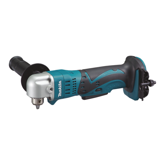
BDA340/BDA350
14.4V/18V Cordless Angle Drill 10mm (3/8")
Battery
Battery
type
quantity
cover
No
---
No
2
1
BL1430
1
No
Battery
Battery
type
quantity
cover
No
---
No
2
1
BL1830
1
No
BDA340
=rpm
0 - 1,700
1
Steel
Wood
1.5 (3.3)*
Battery BL1430 (for BDA340)
Battery BL1830 (for BDA350)
Plastic carrying
Charger
case
No
No
DC18RA
Yes
Plastic carrying
Charger
case
No
No
DC18RA
Yes
BDA350
14.4
3.0
Li-ion
230
280
0 - 1,800
Keyed
1.5 (1/16) - 10 (3/8)
10 (3/8)
25 (1)
Yes
Yes
Yes
Yes
1.6 (3.5)**
Note: The standard equipment for the tool shown above may differ
by country.
BDA340
BDA350
Dimensions: mm (")
BDA340
Length (L)
Width (W)
Height (H)
97 (3-13/16) 115 (4-1/2)
Offered to
All countries
North America
All countries except
North America
Offered to
All countries
North America
All countries except
North America
18
*with Battery BL1430
**with Battery BL1830
Drill bits for wood
Fast charger DC18RA
Drill bits for steel
Belt clip
PRODUCT
P 1/ 7
L
H
W
BDA350
314 (12-3/8)
79 (3-1/8)
Advertisement

Related Manuals for Makita BDA340 Series


Summary of Contents for Makita BDA340 Series
- Page 1 ECHNICAL INFORMATION PRODUCT P 1/ 7 Model No. BDA340/BDA350 Description 14.4V/18V Cordless Angle Drill 10mm (3/8") ONCEPT AND MAIN APPLICATIONS Models BDA340 and BDA350 have been developed as the DC version tools BDA340 of Model DA3010F, featuring: Compact and lightweight design obtained by using Li-ion battery as a power unit High power 4-pole motor for excellent drilling performance BDA350...
-
Page 2: Necessary Repairing Tools
Center attachment for 1R045 Removing Spiral bevel gear 26 from Key 4 (BDA340 / 350) [2] LUBRICATION Apply Makita grease N. No.2 to the following portions designated with the black triangle to protect parts and product from unusual abrasion. Item No. - Page 3 P 3/ 7 epair [3] DISASSEMBLY/ASSEMBLY [3]-1. Drill Chuck S10, Spiral Bevel Gear 26 DISASSEMBLING Refer to Figs. 2 to 7. Fig. 2 Fig. 3 To fit 1R292 to the notch of Bearing Remove Bearing retainer 36-43 with 1R292 notch for fitting retainer, enlarge this width from 30mm by turning it clockwise.
- Page 4 P 4/ 7 epair [3] DISASSEMBLY/ASSEMBLY [3]-1. Drill Chuck S10, Spiral Bevel Gear 26 (cont.) ASSEMBLING 1) If the jaws of Drill chuck are open, make them close for smooth assembling of Ball bearing 6806DDW and Spiral bevel gear 26. Refer to Fig. 6. 2) Do not forget to assemble Key 4 to Drill chuck S10.
-
Page 5: Motor Section
P 5/ 7 epair [3] DISASSEMBLY/ASSEMBLY [3]-4. Motor Section DISASSEMBLING (1) Disassemble Gear housing and Gear housing cover from Motor housing by unscrewing 4x45 Tapping screws. (Fig. 8) (2) Remove Motor section from Housing set (L) in the order of Figs.12, 13. (3) When removing Armature from Brush holder, take the steps illustrated in Figs. - Page 6 P 6/ 7 epair [3] DISASSEMBLY/ASSEMBLY [3]-4. Motor Section (cont.) Fig. 12R Fig. 12F ASSEMBLING Correct Wrong Commutator (1) Assemble Armature as illustrated in Fig. 12R. Commutator of Armature Note: Pay attention to the position of notch of Yoke unit. of Armature It has to be located on the opposite side of Commutator.
-
Page 7: Circuit Diagram
P 7/ 7 ircuit diagram Fig. D-1 When connecting Lead wires of Brush holder Color index of lead wires' sheath complete to Switch, connect them as follows. Black * Lead wire (black) to M2 Terminal White * Lead wire (red) to M1 Terminal Brush holder complete Switch Terminal...