Dell Precision 7820 Tower Owner's Manual
Hide thumbs
Also See for Precision 7820 Tower:
- Owner's manual (105 pages) ,
- Installation manual (15 pages)

Related Manuals for Dell Precision 7820 Tower


Summary of Contents for Dell Precision 7820 Tower
- Page 1 Dell Precision 7820 Tower Owner's Manual Regulatory Model: D02T Regulatory Type: D02T001 May 2020 Rev. A04...
- Page 2 A WARNING indicates a potential for property damage, personal injury, or death. © 2020 Dell Inc. or its subsidiaries. All rights reserved. Dell, EMC, and other trademarks are trademarks of Dell Inc. or its subsidiaries. Other trademarks may be trademarks of their respective owners.
-
Page 3: Table Of Contents
Contents 1 Chassis............................7 Front view....................................7 Back view....................................8 Internal view................................... 9 Major components of your system ............................11 2 Working on your computer......................13 Safety instructions................................13 Turning off your computer — Windows........................... 13 Before working inside your computer..........................14 After working inside your computer...........................14 3 Removing and installing components.................... - Page 4 Front input and output panel............................. 40 Removing front input and output panel........................40 Installing front input and output panel........................43 Input and output panel bracket............................44 Removing input and output panel bracket......................... 44 Installing input and output panel bracket........................45 VROC module..................................45 Removing the VROC module............................
- Page 5 Updating the BIOS in Windows ............................113 Updating BIOS on systems with BitLocker enabled....................114 Updating your system BIOS using a USB flash drive....................114 Updating the Dell BIOS in Linux and Ubuntu environments..................115 Flashing the BIOS from the F12 One-Time boot menu....................115 MegaRAID controller options............................118 System and setup password.............................
- Page 6 Audio drivers..................................123 Storage controller drivers..............................123 Other drivers..................................123 8 Troubleshooting........................125 Dell Enhanced Pre-Boot System Assessment — ePSA Diagnostic 3.0..............125 Running the ePSA Diagnostics...........................125 Hard drive indicator codes..............................126 Preboot blinking power button codes..........................127 9 Contacting Dell......................... 130...
-
Page 7: Chassis
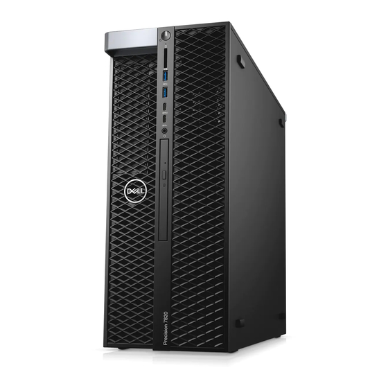
Chassis This chapter illustrates the multiple chassis views along with the ports and connectors and also explains the FN hot key combinations. Topics: • Front view • Back view • Internal view • Major components of your system Front view 1. -
Page 8: Back View
Back view 1. PSU BIST LED 2. Power supply unit 3. Microphone /Line-in port 4. Line-out port 5. Serial port 6. PS/2 Mouse port 7. PS/2 Keyboard port 8. Network port 9. USB 3.1 Gen1 ports 10. USB 3.1 Gen1 port(supports smart Power-On) 11. -
Page 9: Internal View
Internal view 1. PSU bracket 2. HDD bezel lock/unlock button 3. ODD 5.25" bracket 4. Intrusion switch 5. PCIe holder 6. System board 7. GPU 8. Air shroud Chassis... - Page 10 1. Heat sink 2. PSU distribution board 3. System fan 4. 5.25 inch ODD bracket 5. Speaker 6. 2.5 inch Optical disk drive 7. Front system fan 8. Coin cell battery 9. Half length PCIe card 10. Rear system fan Chassis...
-
Page 11: Major Components Of Your System
Major components of your system This section illustrates the major components of your system along with its location. 1. Side cover 2. PCIe holder 3. Internal chassis speaker 4. Intrusion switch 5. 5.25 inch ODD bracket 6. System fan 7. NVMe Flexbay 8. - Page 12 NOTE: Dell provides a list of components and their part numbers for the original system configuration purchased. These parts are available according to warranty coverages purchased by the customer. Contact your Dell sales representative for purchase options. Chassis...
-
Page 13: Working On Your Computer
Damage due to servicing that is not authorized by Dell is not covered by your warranty. Read and follow the safety instructions that came with the product. -
Page 14: Before Working Inside Your Computer
NOTE: Ensure that the computer and all attached devices are turned off. If your computer and attached devices did not automatically turn off when you shut down your operating system, press and hold the power button for about 6 seconds to turn them off. Before working inside your computer To avoid damaging your computer, perform the following steps before you begin working inside the computer. -
Page 15: Removing And Installing Components
Removing and installing components Topics: • Screw size list • Recommended tools • Power supply unit (PSU) • Side cover • Front bezel • Hard Disk Drive bezel • Hard disk drive assembly • NVMe Flexbay • Slim Optical Disk Drive •... -
Page 16: Recommended Tools
Table 1. Screw list (continued) Component Screw type Quantity HDD Bracket M3X5.0mm 5.25" ODD Bracket #6-32 UNC X6.0mm M3X5.0mm System Board #6-32X1/4 inches Middle Fan Fixed Bracket #6-32X1/4 inches Middle Fan Bracket #6-32X1/4 inches Rear Fan Bracket #6-32X1/4 inches HSBP Board M3X5.0mm Slim ODD Fixed Bracket M2X2.0mm... -
Page 17: Installing The Psu
Installing the PSU 1. Slide in the power supply unit to the PSU slot on the system. 2. Connect the power cable to the system. 3. Follow the procedure in After working inside your computer Side cover Removing the side cover 1. - Page 18 4. Pull the latch [1] upward and rotate it to release the cover [2]. Removing and installing components...
-
Page 19: Installing The Side Cover
5. Lift the cover to remove it from the system. Installing the side cover 1. First hold and align the bottom of the side cover to the chassis. 2. Ensure that the hook on the bottom of the side cover snaps into the notch on the system. 3. - Page 20 a. Press the latch and pry the retention tabs to release the front bezel from the system. b. Rotate the bezel forward and lift the front bezel away from the system. Removing and installing components...
-
Page 21: Installing The Front Bezel
Installing the front bezel 1. Hold the bezel and ensure that the hooks on the bezel snap into the notches on the system. 2. Rotate the bezel forward and press the front bezel until the tabs click into place. 3. Follow the procedure in After working inside your computer. -
Page 22: Installing Hdd Bezel
Installing HDD bezel 1. Hold the bezel and ensure that the hooks on the bezel snap into the notches on the system. 2. Press the blue lock button on the left edge of the ODD bay to secure the bezel to the system. 3. - Page 23 a. Press the release button [1] to unlock the latch [2]. b. Pull the latch to slide the carrier out of the HDD slot. Removing and installing components...
-
Page 24: Installing The Hdd Carrier
Installing the HDD carrier 1. Slide the carrier into the drive bay until it clicks into place. CAUTION: Ensure that the latch is open before installing the carrier. 2. Lock the latch. 3. Install the following components: HDD bezel side cover 4. - Page 25 3. To remove the 3.5 inch HDD: a. Expand one side of the carrier. b. Lift the hard drive out of the carrier. 4. To remove the 2.5 inch HDD: a. Expand two sides of the carrier. b. Lift the hard drive out of the carrier. Removing and installing components...
-
Page 26: Installing The Hdd
Installing the HDD 1. Insert the HDD to its slot in the HDD bracket with the connector end of the hard drive towards the back of the HDD carrier. 2. Slide the HDD carrier back into the hard drive bay. 3. - Page 27 b. Pull the latch to slide the carrier out of the HDD slot. Removing and installing components...
- Page 28 4. To remove the SSD carrier from the NVMe flexbay: a. Press the release button to slide the M.2 SSD carrier out of the NVMe flexbay. b. Pull the M.2 SSD carrier out of the NVMe flexbay. Removing and installing components...
- Page 29 5. To remove the SSD from the SSD carrier: a. Remove the screws on either side of the SSD. b. Remove the screw from the top of the SSD carrier. Removing and installing components...
- Page 30 c. Slide the SSD cover from the top of the carrier. d. Slide the SSD out of the M.2 slot on the carrier. Removing and installing components...
-
Page 31: Installing The Nvme Flexbay
Installing the NVMe flexbay 1. To install the SSD in the carrier: a. Remove the dummy SSD blank from the SSD carrier. b. Peel off the tape from the SSD carrier. Removing and installing components... - Page 32 c. Peel off the adhesive tape from the SSD carrier cover. 2. Install the SSD in the carrier Removing and installing components...
-
Page 33: Slim Optical Disk Drive
3. Replac the two side screws and the central screw. 4. To install the SSD carrier slide the carrier in the NVMe flexbay until it clicks in place. 5. Slide the carrier into the drive bay until it clicks into place. CAUTION: Ensure that the latch is open before installing the carrier. - Page 34 b. Slide the slim ODD out of the system. Removing and installing components...
-
Page 35: Installing The Slim Odd
Installing the slim ODD 1. Slide the slim ODD into the slot on the chassis. 2. Tighten the screw to secure the slim ODD to the chassis. 3. Install the side cover. 4. Follow the procedure in After working inside your computer. - Page 36 b. Lift the bezel from the chassis. Removing and installing components...
-
Page 37: Installing Front Input And Output Bezel
Installing front input and output bezel 1. Hold the input and output(I/O) bezel and ensure that the hooks on the bezel snap into the notches on the system. 2. Press the retention tabs and secure them to the chassis. 3. Install the : front bezel side cover 4. - Page 38 b. Remove the five screws[1,2] that secure the bracket to the chassis. Removing and installing components...
- Page 39 c. Slide the ODD bracket toward the rear of the system and lift it away from the chassis. Removing and installing components...
-
Page 40: Installing The 5.25 Odd Bay
Installing the 5.25 ODD bay 1. Place the ODD bracket into the system slot. 2. Replace the (6-32 X 6.0mm) screws. 3. Place the ODD filler back into the slot. 4. Install the: front bezel side cover 5. Follow the procedure in After working inside your computer Front input and output panel Removing front input and output panel... - Page 41 NOTE: Do not pull the connector by the cable wires. Instead, disconnect the cable by pulling the connector end. Pulling the cable wires may loosen them from the connector. b. Remove the screw that secures the front I/O panel to the chassis. Removing and installing components...
- Page 42 c. Slide the I/O panel out of the chassis. Removing and installing components...
-
Page 43: Installing Front Input And Output Panel
Installing front input and output panel 1. Insert the input and output(I/O) panel onto its slot in the system. 2. Slide the panel to secure the hooks into the chassis hole. 3. Tighten the screw to secure the front I/O panel to the chassis. 4. -
Page 44: Input And Output Panel Bracket
Input and output panel bracket Removing input and output panel bracket 1. Follow the procedure in Before working inside your computer. 2. Remove the: side cover front bezel front input and output bezel 5.25 inch ODD bracket front input and output panel 3. -
Page 45: Installing Input And Output Panel Bracket
Installing input and output panel bracket 1. Insert the input and output(I/O) panel into the metal bracket. 2. Replace the screws to secure the I/O panel bracket to the I/O panel. 3. Install the: front input and output panel front input and output bezel 5.25 inch ODD bracket front bezel side cover... -
Page 46: Installing The Vroc Module
Installing the VROC module Plug-in the VROC module to the system board. Intrusion switch Removing the Intrusion switch 1. Follow the procedure in Before working inside your computer. 2. Remove the: side cover front bezel 5.25 inch ODD bracket 3. To remove the intrusion switch: a. -
Page 47: Installing The Intrusion Switch
Installing the intrusion switch 1. Place the intrusion switch into the slot in the system chassis. 2. Replace the screw and secure the switch to the chassis. 3. Connect the cable to the system board. 4. Install the: 5.25 inch ODD bracket front bezel side cover 5. -
Page 48: Installing The Internal Chassis Speaker
side cover front bezel 5.25 inch ODD bracket 3. To remove the internal chassis speaker: a. Disconnect the speaker cable [1] from the front I/O module. b. Press the speaker securing tabs [2], then pull to release it from the system. c. -
Page 49: Air Shroud
Air shroud Removing the air shroud 1. Follow the procedure in Before working inside your computer. 2. Remove the side cover 3. To remove the air shroud: a. Holding the shroud at both the ends, press the tabs[1] and then lift the shroud[2] from the system. Installing the air shroud 1. -
Page 50: Installing The Memory Module
side cover air shroud 3. Press the memory module retention tabs on each side of the memory module. 4. Lift the memory module out of the memory slot on the system board. WARNING: Rotating the memory module out of the slot will cause damage to the memory module. Ensure to pull it straight out of the memory module slot. - Page 51 c. Lift the GPU from the PCIe slot on the system board. Removing and installing components...
-
Page 52: Installing The Gpu
Installing the GPU 1. Align and place the GPU to the PCIe slot on the system board. 2. Press it down so that it is securely seated on the slot. 3. Connect the power cable to the GPU. 4. Lock both the blue clips forward on the filler bracket to secure the GPU to the system board. 5. -
Page 53: Installing The Coin Cell Battery
b. Lift the coin-cell battery out of the system board. Installing the coin cell battery 1. Place the coin-cell battery into its slot on the system board. 2. Press the coin-cell battery with positive (+) side facing up until the release latch springs back into place and secures it to the system board. - Page 54 air shroud front bezel 5.25 inch ODD bracket graphical processing unit(GPU) 3. To remove the system fan: a. Press the connector tab and disconnect the two fan cables from the system board. NOTE: Do not pull the connector by the cable wires. Instead, disconnect the cable by pulling on the connector end.
-
Page 55: Installing The System Fan
Installing the system fan 1. Align the system fan to its slot on the system board and secure it with the 3 screws. 2. Connect the fan cables to the slot on the system board. 3. Install the: graphical processing unit(GPU) 5.25 ODD bracket front bezel air shroud... -
Page 56: Installing The Fan Into The Fan Bracket
Installing the fan into the fan bracket 1. Place the fan into the fan bracket. 2. Tighten the grommets that secure the fan to the fan bracket. 3. Install the: system fan side cover 4. Follow the procedure in After working inside your computer Removing and installing components... -
Page 57: Pcie Holder
PCIe holder Removing PCIe holder 1. Follow the procedure in Before working inside your computer. 2. Remove the: side cover graphical processing unit(GPU) 3. To remove the PCIe holder: a. Disconnect the two power cables from the cable slot in the PCIe holder [1]. b. -
Page 58: Rear System Fan
graphical processing unit(GPU) side cover 5. Follow the procedure in After working inside your computer. Rear system fan Removing the rear system fan 1. Follow the procedure in Before working inside your computer. 2. Remove the: side cover processor heat sink module(PHM) 3. - Page 59 d. Press the tab[2] to detach the fan from the system. e. Rotate the fan forward and lift it away from the system. Removing and installing components...
-
Page 60: Installing The Rear System Fan
Installing the rear system fan 1. Insert the fan assembly on one side to align it with the screw tab on the PSU bracket. 2. Press the assembly on the other side to align it with the screw tab on the PCI bracket. 3. - Page 61 • SATA 0,1 cable [1] • SATA 2, 3, 4, 5 cable [2] • ODD 0, 1 cable [3] • USB 3.1 cable [4] NOTE: Do not pull the connector by the cable wires. Instead, disconnect the cable by pulling the connector end. Pulling the cable wires may loosen them from the connector.
-
Page 62: Installing The Front System Fan
Installing the front system fan 1. Align the front system fan to its retention slot in the system chassis. 2. Replace the screw that secures the front system fan to the chassis. 3. Connect the fan cable to the system board. 4. -
Page 63: Processor Heat Sink Module
Processor heat sink module Removing the processor heat sink module 1. Follow the procedure in Before working inside your computer. NOTE: Ensure that you have Torx 30 screwdriver to remove the processor heat sink module (PHM). 2. Remove the: side cover air shroud 3. -
Page 64: Installing The Processor Heat Sink Module
Installing the processor heat sink module 1. Place the heat sink on the CPU slot. 2. Replace the four screws in the diagonal order (1,2,3,4), to secure the heat sink to the system board. 3. Install the: air shroud side cover 4. -
Page 65: Installing The Cpu
d. Use a torx screwdriver to pry the CPU off the processor heat sink module. Place the blade between the clip and the CPU. NOTE: A flatbed screwdriver or plastic scribe can also be used as well. e. Unlatch the CPU from the two keying latches on the processor carrier and gently lift the CPU. NOTE: Avoid touching the CPU contacts with your fingers. - Page 66 3. Flip both the processor and the carrier over so that the pins on the processor and the logo side of the carrier are facing up. 4. Carefully insert the processor into the carrier so that it is secured by the hooks on the upper and lower side of the carrier. NOTE: After inserting the processor into the carrier, check to see whether the small triangle on the processor aligns with the triangle on the carrier.
- Page 67 6. Insert the processor and carrier assembly into the heat sink so that the hooks on the four corners of the carrier are locked into the openings of heat sink. NOTE: After inserting the processor and carrier assembly into the heat sink, double check to see whether the triangle on the carrier is located on the bottom right corner of the heat sink (when the bottom side of the heat sink is facing up).
-
Page 68: Removing The 2 Nd Processor And Expansion Card
8. Install the: heat sink air shroud side cover 9. Follow the procedure in After working inside your computer Removing the 2 Processor and expansion card 1. Follow the procedure in Before working inside your computer. 2. Remove the side cover. - Page 69 c. Disconnect the power cable from the expansion card d. Press and release the expansion card latch Removing and installing components...
- Page 70 e. Lift and remove the expansion card from the computer 4. To remove the CPU0 and the heatsink assembly a. Remove the air shroud on the CPU0 Removing and installing components...
- Page 71 b. Remove the screw securing the metal bracket to the chassis c. Disconnect the HDD and ODD cable and remove the metal separator from the system Removing and installing components...
- Page 72 d. Loosen the heatsink screws from the system board e. Disconnect the fan cable from the system board Removing and installing components...
- Page 73 f. Lift and remove the CPU0 along with heatsink from the computer 5. To remove the processor from the heatsink assembly a. Press and release the latch that secures the CPU to the heatsink assembly Removing and installing components...
-
Page 74: Installing The 2 Nd Processor And Expansion Card
b. Pry the securing tabs to release the processor from the heatsink assembly Installing the 2 Processor and expansion card 1. To install the processor on the heatsink assembly: a. Apply thermal gel on the processor. Removing and installing components... - Page 75 b. Replace the processor on the heatsink assembly c. Press the latch to secure the processor on the heatsink assembly Removing and installing components...
- Page 76 2. Install the CPU 0 and the heatsink assembly a. Install the CPU 0 preassembled with the heatsink assembly on the system board b. Connect the fan cable for CPU 0 to the system board Removing and installing components...
- Page 77 c. Tighten the heatsink screws to the system board d. Remove the cap from the CPU 1 connector(in upgrading scenarios Removing and installing components...
- Page 78 e. Pass the hard drive and optical drive cable through the metal separator. f. Replace the screw and secure the metal separator to the chassis Removing and installing components...
- Page 79 g. Replace the air shroud for the CPU 0 3. To install the CPU1 and the expansion card a. Replace the expansion card on the computer Removing and installing components...
- Page 80 b. Press and secure the expansion card latch c. Connect the power cable to the expansion card Removing and installing components...
- Page 81 d. Install the heatsink assembly pre-assembled with the CPU1 and tighten the screws [1] e. Install the heatsink assembly pre-assembled with the CPU1 and tighten the screws [1] Removing and installing components...
-
Page 82: System Board
4. Install the side cover 5. Follow the procedure in After working inside your computer System board Removing system board 1. Follow the procedure in Before working inside your computer. 2. Remove the: side cover air shroud memory module system fan rear system fan PCIe card holder 3. - Page 83 d. Disconnect the following cables from the system board connectors: • audio cable [1] • power cable [2] • cable holder [3] • power control cable [4] • 24 Pin power cable [5] • front I/O panel [6] Removing and installing components...
- Page 84 e. Disconnect the following cables: • SATA 2, 3, 4, 5 cable [1] • SATA 0,1 cable [2] • ODD 0, 1 cable [3] • USB 3.1 cable [4] • Front system fan cable [5] NOTE: Do not pull the connector by the cable wires . Instead, disconnect the cable by pulling on the connector end.
- Page 85 f. Remove the screws that secure the system board to the chassis. Removing and installing components...
- Page 86 g. Slide the system board towards HDD bracket module to detach it from the system. Removing and installing components...
- Page 87 h. Lift the system board up to remove it from the chassis. Removing and installing components...
-
Page 88: Installing The System Board
Installing the system board 1. Align and place the system board into the chassis. 2. Slide the system board to its position. 3. Replace the screws to secure the system board to the chassis. 4. Place the system fan fixed bracket and replace the single screw on the system board. 5. -
Page 89: System Board Components
System board components The following image displays the system board components. 1. Slot 6 PCI 2. Slot PCI 3x16 3. Memory slots 4. CPU0 5. Memory slots 6. Front panel audio port 7. Power CPU port 8. Rear fan 0 port 9. -
Page 90: Technology And Components
This section provides information about the technologies that comes with the Dell Precision 7820 Tower. The following table lists the basic of technologies that are available on the Dell Precision7820 Tower systems for Dell internal users only. Table 2. Technologies list... - Page 91 Dell UltraSpeed Duo (PCIE M.2 Interposer) Remote Solutions 1-1 Teradici PCoIP • CLIENT: Dell or other Branded Zero Client (TERA Gen 2) (Dell-Wyse P25) DUAL Monitor Support • HOST: PCIe x1 PCoIP Dual Host Card (TERA Gen 2) • CLIENT: Dell or other Branded Zero Client (TERA Gen 2)
-
Page 92: Megaraid 9440-8I And 9460-16I Controller
Table 2. Technologies list(continued) Category Technology Browser Path • HOST: PCIe x1 PCoIP Quad Host Card (TERA Gen 2) • Support Dual Terra Card configurations NOTE: For further information about the Teradici PCoIP Card host driver installation, see Teradici PCoIP. MegaRAID 9440-8i and 9460-16i controller Small and medium businesses (SMBs) deploying entry-level server platforms and workstations need affordable, reliable storage solutions. - Page 93 Key Features: • Tri-Mode SerDes Technology enables the operation of NVMe, SAS or SATA devices in a single drive bay, allowing for endless design flexibility • Supports 12, 6, and 3 Gb/s SAS and 6, 3 Gb/s SATA data transfer rates •...
-
Page 94: Teradici Pcoip
This section provides an overview of the host driver installation process. Installing the Teradici PCoIP Card Host Dual/Quad Install the PCoIP host driver software from dell.com/support. NOTE: You cannot upgrade the PCoIP host driver software while a VMware View-brokered PCoIP session is active between a host workstation or host PC and VMware View client. - Page 95 Portal and Host Card If the Dell Precision Workstation comes equipped with the optional Teradici PCoIP Portal and Host Card, make sure the power management cable on the Teradici card is connected properly on the system board. The power management cable from the Teradici card must be plugged into the correct Power remote connection on the system board.
- Page 96 remote connector labeled 22 on the system board diagram: Make sure the power management cable from the Teradici card is not plugged into either the two-pin Clear CMOS or Clear PSWD jumpers. Technology and components...
- Page 97 Plugging the power management cable into the Clear CMOS jumper will cause the BIOS to reset when sending a remote restart request to the Teradici card. You will then have to reset the time and BIOS settings. If the power management cable from the Teradici card is plugged into the Clear PSWD jumper, then the BIOS password will be cleared and a new one will need to be configured.
-
Page 98: System Specifications
System specifications Topics: • System specifications • Memory specifications • Video specifications • Audio specifications • Network specifications • Card slots • Storage specifications • External connectors • Power specifications • Physical specifications • Environmental specifications System specifications Feature Specification Processor type •... -
Page 99: Audio Specifications
Features Specifications • NVIDIA Quadro P6000 • NVIDIA Quadro P5000 • Radeon Pro WX 7100 • Radeon Pro WX 5100 • Radeon Pro WX 4100 • NVIDIA Quadro P4000 • NVIDIA Quadro P2000 • Radeon Pro WX 3100 • Radeon Pro WX 2100 •... -
Page 100: Storage Specifications
DVD-ROM; DVD+/-RW 5.25” Bay Options: BD, DVD+/-RW Accessible Internally • M.2 NVMe PCIe SSDs — Up to 4 x 1TB drives on 1 Dell Precision Ultra-Speed Drive Quad x16 cards Accessible • Front FlexBay M.2 NVMe PCIe SSDs —Up to 2 x 1TB drives •... - Page 101 Temperature Specifications NOTE: * Starting at 5000 ft, the maximum operating ambient temperature is derated by 1 C (1.8 F) per 1000 ft up to 10,000 ft. Storage -40 °C to 65 °C(-40 F to 149 F) Relative Specifications humidity (maximum) Operating 8% to 85% (non-condensing)
-
Page 102: System Setup
System Setup Topics: • General options • System configuration • Video • Security • Secure boot • Performance • Power management • Post behaviour • Manageability • Virtualization support • Maintenance • System logs • Advanced configurations • SupportAssist system resolution •... -
Page 103: System Configuration
Table 4. General(continued) Option Description Advanced Boot Options Allows you to Enable Legacy Option ROMs. The options are: • Enable Legacy Option ROMs—Default • Enable Attempt Legacy Boot UEFI Boot Path Security Allows you to control whether the system prompts the user to enter the Admin password when booting to a UEFI boot path. - Page 104 Table 5. System Configuration(continued) Option Description NOTE: SATA is configured to support RAID mode. Drives 7820 Tower Allows you to enable or disable various drives on board. The options are: • MiniSAS PCIe SSD-0 • SATA-0 • SATA–2 • SATA–4 •...
- Page 105 • Internal Port 2 This option is set by default. Dell Type-C Dock Configuration Allows you to connect to Dell WD and TB family of docks. Always Allows Dell Docks This option is set by default. Thunderbolt Adapter Configuration Allows you to enable or disable the Thunderbolt device support capability.
-
Page 106: Video
Table 5. System Configuration(continued) Option Description • Enable PCI Slot—Default • Secure Digital (SD) Card Boot • Enable Secure Digital (SD) Card—Default • Secure Digital (SD) Card Read-Only Mode Intel VMD Technology Allows you to enable or disable VMD on the front PCIe bays. •... - Page 107 Table 7. Security(continued) Option Description The entries to set password are: • Enter the old password: • Enter the new password: • Confirm new password: Click OK once you set the password. NOTE: For the first time login, "Enter the old password:" field is marked to "Not set". Hence, password has to be set for the first time you login and then you can change or delete the password.
-
Page 108: Secure Boot
Table 7. Security(continued) Option Description Computrace (R) Allows you to activate or disable the optional Computrace software. The options are: • Deactivate—Default • Disable • Activate Chassis Intrusion Allows you to control the chassis intrusion feature. Click one of the following options: •... -
Page 109: Performance
Allows you to enable or disable the HyperThreading in the processor. • Disabled • Enabled—Default Dell Reliable Memory Technology (RMT) Allows you to identify and isolate memory errors in system RAM. • Enable Dell RMT—Default • Clear Dell RMT System Setup... -
Page 110: Power Management
Table 9. Performance(continued) Option Description System Isochronous Mode Allows you to enable or disable this mode to reduce latency of memory transactions at the expense of bandwidth. : Click one of the options: • Disabled(Default) • Enabled RAS Support Allows you to report or log errors caused by memory failures, the PCIe failures, CPU failures. -
Page 111: Post Behaviour
Table 10. Power Management(continued) Option Description All the options are not set by default. Block Sleep Allows you to block entering to sleep(S3 state) in OS Environment. This option is not set by default. Post behaviour Table 11. POST Behavior Option Description Numlock LED... -
Page 112: Virtualization Support
Table 12. Manageability(continued) Option Description MEBx Hotkey Allows you to specify if the MEBx Hotkey function should be enabled when the system boots This option is set by default. Virtualization support Table 13. Virtualization Support Option Description Virtualization This option specifies whether a Virtual Machine Monitor (VMM) can utilize the additional hardware capabilities provided by the Intel Virtualization technology. -
Page 113: System Logs
Table 17. SupportAssit System Resolution Option Description Auto OS Recovery The Auto OS Recovery Threshold setup option controls the automatic boot flow for Support Assist Threshold System Resolution Console and Dell OS Recovery tool. Click one of the following options: • • • 2—Default •... -
Page 114: Updating Bios On Systems With Bitlocker Enabled
3. Insert the USB flash drive into the system that requires the BIOS update. 4. Restart the system and press F12 when the Dell splash logo appears to display the One Time Boot Menu. 5. Using arrow keys, select USB Storage Device and click Enter. -
Page 115: Updating The Dell Bios In Linux And Ubuntu Environments
Most Dell systems built after 2012 have this capability and you can confirm by booting your system to the F12 One-Time Boot Menu to see if BIOS FLASH UPDATE is listed as a boot option for your system. If the option is listed, then the BIOS supports this BIOS update option. - Page 116 3. The Bios flash menu will open then click the Flash from file. 4. Select external USB device System Setup...
- Page 117 5. Once the file is selected, Double click the flash target file, then press submit . 6. Click the Update BIOS then system will reboot to flash the BIOS. System Setup...
-
Page 118: Megaraid Controller Options
7. Once complete, the system will reboot and the BIOS update process is completed. MegaRAID controller options During bootup, press <Ctrl> + <R> when prompted by the BIOS screen to get to the BIOS configuration utility. Table 18. MegaRAID configuration utility Option Description VD Mgmt (Virtual Device Management) -
Page 119: System And Setup Password
Table 18. MegaRAID configuration utility(continued) Option Description Properties The Properties screen displays the controller properties like current versions of the controller BIOS, the MegaRAID firmware the Configuration Utility and the Boot block. NOTE: Press <Ctrl> + <N> to move to the next screen and Press <Ctrl> + <P> to go back to the previous screen. System and setup password Table 19. - Page 120 4. Select Setup Password, alter or delete the existing setup password and press Enter or Tab. NOTE: If you change the System and/or Setup password, re enter the new password when prompted. If you delete the System and Setup password, confirm the deletion when prompted. 5.
-
Page 121: Software
NeoKylin v6.0 Downloading drivers 1. Turn on the computer. 2. Go to Dell.com/support. 3. Click Product Support, enter the Service Tag of your system, and then click Submit. NOTE: If you do not have the Service Tag, use the auto detect feature or manually browse for your system model. -
Page 122: Graphics Controller Driver
Graphics controller driver Verify if the graphics controller driver is already installed in the computer. Ports Verify if the drivers for the ports are already installed in the computer. USB drivers Verify if the USB drivers are already installed in the computer. Software... -
Page 123: Network Driver
Network driver The driver is labeled as Intel I219-LM Ethernet Driver. Audio drivers Verify if the audio drivers are already installed in the computer. Storage controller drivers Verify if the storage controller drivers are already installed in the computer. Other drivers This section lists different driver details for all the other components in the Device Manager. - Page 124 Human Interface Device drivers Verify if the human interface device drivers are already installed in the computer. Firmware Verify if the Firmware drivers are already installed in the computer. Software...
-
Page 125: Troubleshooting
Invoke diagnostics boot by either of the methods that are suggested below: 1. Power on the computer. 2. As the computer boots, press the F12 key when the Dell logo is displayed. 3. In the boot menu screen, use Up/Down arrow key to select the Diagnostics option and then press Enter. -
Page 126: Hard Drive Indicator Codes
Hard drive indicator codes Each hard drive carrier has an activity LED indicator and a status LED indicator. The indicators provide information about the current status of the hard drive. The activity LED indicator indicates whether the hard drive is currently in use or not. The status LED indicator indicates the power condition of the drive. -
Page 127: Preboot Blinking Power Button Codes
NOTE: If the hard drive is in the Advanced Host Controller Interface (AHCI) mode, the status LED indicator does not turn on. NOTE: Drive status indicator behavior is managed by Storage Spaces Direct. Not all drive status indicators may be used. Table 21. - Page 128 Table 23. Diagnostic Indicator table (continued) Power Light: Amber-White Amber/White Blinking Problem Description Suggested Resolution Blinking Pattern 1 amber blink followed by a short Bad system board, Memory or • If you can assist to pause, 3 white blinks, long Processor troubleshoot, narrow down pause, then repeats...
- Page 129 Table 23. Diagnostic Indicator table (continued) Power Light: Amber-White Amber/White Blinking Problem Description Suggested Resolution Blinking Pattern the issue by removing one by one the memory on motherboard to determine which one failed. • Contact Tech Support. 2 amber blinks followed by a Motherboard: Chipset •...
-
Page 130: Contacting Dell
Dell product catalog. Dell provides several online and telephone-based support and service options. Availability varies by country and product, and some services may not be available in your area. To contact Dell for sales, technical support, or customer service issues: 1.