Datalogic Matrix 300N Product Reference Manual
Image based reader
Hide thumbs
Also See for Matrix 300N:
- Product reference manual (244 pages) ,
- Reference manual (179 pages) ,
- Product manual (2 pages)
Table of Contents
Advertisement
Quick Links
Advertisement
Table of Contents

Related Manuals for Datalogic Matrix 300N


Summary of Contents for Datalogic Matrix 300N
- Page 1 Matrix 300N™ Image Based Reader Product Reference Guide...
- Page 2 Matrix 300N, ID-NET, DL.CODE and X-PRESS are trademarks of Datalogic S.p.A.and/or its affil- iates. All other trademarks and brands are property of their respective owners. Datalogic shall not be liable for technical or editorial errors or omissions contained herein, nor for incidental or consequential damages resulting from the use of this material.
-
Page 3: Table Of Contents
GENERAL VIEW .................................. XIV RAPID CONFIGURATION ............................... 1 Step 1 - Connect the System ................................1 CBX100/CBX500 Pinout for Matrix 300N ........................2 Step 2 - Mount and Position the Reader ............................3 Step 3 - Aim and Autofocus the Reader ............................4 Step 4 - X-PRESS Configuration .............................. - Page 4 Input 2 Connections Using External Power .........................77 Input 3 Connections (CBX500 Only) ............................78 Outputs ......................................79 Output 1 and 2 Connections Using Matrix 300N Power .....................80 Output 3 Connections Using Matrix 300N Power (CBX500 Only) ..................82 On-Board Ethernet Interface .................................83 User Interface - Serial Host ................................83 TYPICAL LAYOUTS................................
- Page 5 2 MP Software Adjustable Liquid Lens Models 16 mm (25°) ..................101 Reading Diagrams ..................................102 Matrix 300N 4x1-0xx (6 mm manual) 1D Codes (66°) ...................... 103 Matrix 300N 4x1-x00 (6 mm manual) 2D Codes (66°) ..................... 109 Matrix 300N 4x3-0xx (9 mm manual) 1D Codes (41°) ...................... 112 Matrix 300N 4x3-0xx (9 mm manual) 2D Codes (41°) ......................
- Page 6 Examples for DPM Applications ............................197 Polarized Illuminators ................................. 199 Direct Part Marking Applications ............................... 202 Matrix 300N Recommended Illumination for DPM ........................203 Illumination Examples for DPM Applications ........................204 Code Positioning with Respect to Illumination ......................204 Color Contrast Considerations for DPM Applications ...................... 205 Lighting System Working Distances ............................
-
Page 7: References
• DL.CODE Help Online Support Through The Website Datalogic provides several services as well as technical support through its web- site. Log on to www.datalogic.com. For quick access, from the home page click on the search icon , and type in the name of the product you are looking for. -
Page 8: Conventions
"User" refers to anyone using a Matrix 300N reader. "Reader" refers to the Matrix 300N reader. "You" refers to the System Administrator or Technical Support person using this manual to install, configure, operate, maintain or troubleshoot a Matrix 300N reader. viii... -
Page 9: Compliance
EU declaration of conformity is available for competent authorities and custom- ers through Datalogic commercial reference contacts. The main European direc- tives applicable to Datalogic products require inclusion of an adequate analysis and assessment of the risk(s). This evaluation was carried out in relation to the applicable points of the standards listed in the Declaration of Conformity. -
Page 10: Fcc Compliance
LED Safety LED emission according to EN 62471. Laser Safety The Matrix 300N internal illuminators contain two aiming Laser LEDs used to position the reader. This product conforms to the applicable requirements of IEC 60825-1 and com- plies with 21 CFR 1040.10 except for deviations pursuant to Laser Notice N° 50, date June 24, 2007. - Page 11 Disconnect the power supply when opening the device during maintenance or installation to avoid exposure to hazardous laser light. The laser beam can be switched on or off through a software command. General Matrix 300N Warning Labels Product Reference Guide...
-
Page 12: Handling
Handling The Matrix 300N is designed to be used in an industrial environment and is built to withstand vibration and shock when correctly installed, however it is also a precision product and therefore before and during installation it must be han- dled correctly to avoid damage. - Page 13 Handling • do not weld the reader into position which can cause electrostatic, heat or reading window damage. • do not spray paint near the reader which can cause reading window dam- age. Product Reference Guide xiii...
-
Page 14: General View
General View Matrix 300N™ 1.3 MP Software Adjustable Focus (Liquid Lens) Models Figure A Connector block rotates to 90° position Power - Serial Interfaces - I/O ... - Page 15 General View Matrix 300N™ 1.3 MP Manual Adjustable Focus Models Figure B Connector block rotates to 90° position Device Class and Warning Labels...
- Page 16 General View Matrix 300N™ 2 MP Software Adjustable Focus (Liquid Lens) Models Figure C Connector block rotates to 90° position Power - Serial Interfaces - I/O ...
-
Page 17: Rapid Configuration
External Trigger (photoelectric sensor) when the object enters its reading zone. PG6000 Host CAB-DSxx-S Matrix 300N Main Serial Interface (RS232 or RS422 Full-Duplex External Trigger (for One Shot or Phase Mode) I/O, Aux Figure 1 - Matrix 300N in Stand Alone Layout Product Reference Guide... -
Page 18: Cbx100/Cbx500 Pinout For Matrix 300N
Rapid Configuration CBX100/CBX500 Pinout for Matrix 300N The table below gives the pinout of the CBX100/CBX500 terminal block connectors. Use this pinout when the Matrix 300N reader is connected by means of the CBX100/CBX500: CBX100/500 Terminal Block Connectors Input Power... -
Page 19: Step 2 - Mount And Position The Reader
Step 2 - Mount and Position the Reader Step 2 - Mount and Position the Reader 1. To mount the Matrix 300N, use the mounting brackets to obtain the most suitable position for the reader. The most common mounting configuration is shown in the figure below. -
Page 20: Step 3 - Aim And Autofocus The Reader
If the Autofocus cannot be reached after a timeout of about 3 (three) min- utes, Matrix 300N will exit without saving the parameters to memory, the Aim LED will stop blinking and in this case Matrix 300N emits a long low pitched beep. - Page 21 Step 3 - Aim and Autofocus the Reader (Manual Adjustable Focus Models only) The Matrix 300N manual adjustable focus models are factory focused to a precise Reading Distance. If the distance is compatible with your application, you can use the X-PRESS Interface to install the reader, if not, use the DL.CODE procedure described in step 6 “Advanced Setup...
-
Page 22: Step 4 - X-Press Configuration
Rapid Configuration Step 4 - X-PRESS Configuration Once Matrix 300N is focused at the correct reading distance, you must configure it for optimal code reading relative to your application. 1. Enter the Aim function by pressing and holding the X-PRESS push button until the Aim LED is on. -
Page 23: Learn
You can always exit from any X-PRESS function at any time by pressing the X-PRESS push button once. After a short delay the procedure is canceled. NOTE If you have used this procedure to configure Matrix 300N, go to step 7. NOTE Product Reference Guide... -
Page 24: Reset Reader To Factory Default Environment (Optional)
Release and re-press the button during this LED blinking sequence. All the device Environment parameters are reset including the default IP Address. The Matrix 300N emits 3 high pitched beeps and after a few seconds enters run mode. Any previously saved configurations on the device will remain in memory, but the Default configuration is set as the startup configuration. -
Page 25: Step 5 - Installing Dl.code Configuration Program
NOTE 2. When the installation is complete, the DL.CODE entry is created in the Start>Programs bar under “Datalogic” as well as a desktop icon. Double- click the desktop icon to run it. This configuration procedure assumes a laptop computer running DL.CODE is connected to a factory default reader through the Ethernet port. -
Page 26: Device Discovery
4. Find your device in the list by matching its serial number (SN) then click on the device wrench icon to open the Device Environment Configuration win- dow. 5. Change the Ethernet Settings (IP Address, Subnet Mask, Gateway Address etc.) according to the network requirements. Matrix 300N... - Page 27 Step 5 - Installing DL.CODE Configuration Program Figure 9 - Device Environment Configuration Window 6. Click OK; the device will reappear in the list of Online Devices (in color) meaning it is now part of the LAN and can be configured. The new IP address will also be displayed.
- Page 28 Rapid Configuration 7. Double-click on the device icon or drag it into the Selected Device Informa- tion Area. Details about the device will be displayed in this area. Figure 10 - DL.CODE Opening Window Matrix 300N...
-
Page 29: Step 6 - Device Configuration
Step 6 - Device Configuration Step 6 - Device Configuration Automatic or Advanced Setup Automatic Setup provides an automatic procedure for setting: optical/ illumination, reading distance (for software adjustable focus liquid lens models), and code definition parameters to obtain the most stable decoding conditions for a single code symbology based on the images presented to the reader. -
Page 30: Automatic Setup
Default configuration. Click OK. The device enters run mode and begins acquiring images. 3. Place the application code in front of the reader at the correct application reading distance. 4. Click on the Pause button to stop image acquisition. Matrix 300N... - Page 31 Step 6 - Device Configuration If the image display area is too dark to see the images being captured, you can drag the Gain and Exposure Time sliders (circled in red in the figure above) to the right to increase visibility. This will not affect Automatic Setup. NOTE 5.
- Page 32 Rapid Configuration Your reader is now optimized for decoding. Continue with the Reading Phase configuration described on page 31. Matrix 300N...
-
Page 33: Advanced Setup For Software Adjustable Focus Models (Liquid Lens)
Step 6 - Device Configuration Advanced Setup for Software Adjustable Focus Models (Liquid Lens) For Manual Adjustable Focus models go to page 24 then continue the configuration with the " Reading Phase" on page 31 . NOTE To begin configuration, the reader must be correctly mounted at the correct reading distance for your application so that its Field of View covers the application reading area. - Page 34 5. Click the Image Settings branch and then click the Image Auto Setup button to automatically acquire the best exposure time and gain values. 6. Select the Static or Dynamic Self-Tuning option; Start Autolearn and Apply to the Image Settings. Matrix 300N...
- Page 35 Step 6 - Device Configuration For applications having multiple lighting or code reading conditions, up to 10 different Image Settings can be configured by adding them with the icon. NOTE Product Reference Guide...
- Page 36 7. Now select the General Image Settings branch and click on the Focus Autolearn button. The Reading Distance value is not significant until the Focus Autolearn procedure ends successfully. 8. The Calibrate dialog box opens allowing you to start the procedure. Click Start. Matrix 300N...
- Page 37 Step 6 - Device Configuration At the end of the calibration you can see the new Reading Distance and Image Density (PPI) values as well as the FOV dimensions. Click Apply. To enlarge the visual image of the code view, you can click on the zoom image icon repositioning it on the code.
- Page 38 NOTE 9. Now place an application specific code in front of the reader and repeat only the Image Auto-Setup to register any changes in lighting or code sur- face contrast. Matrix 300N...
- Page 39 Step 6 - Device Configuration 10. Click on the Data Matrix ECC 200 symbology under the Image Settings branch (enabled by default). If this symbology is among those in your appli- cation it will be shown in the image display with its code symbology name and a small green box around it indicating it is decoded.
-
Page 40: Advanced Setup For Manual Adjustable Focus Models
(jobs) saved on the device. For new devices, the only saved job is the Default configuration. Click OK. The device enters run mode and begins acquiring images. 3. Click on the Advanced Setup button and press the Play icon. Matrix 300N... - Page 41 Step 6 - Device Configuration 4. Place the Grade A Barcode Test Chart in the reading area. Once positioned, stop image acquisition by clicking on the Pause button. 5. Click the Image Settings branch and then click the Image Auto Setup button to automatically acquire the best exposure time and gain values.
- Page 42 Rapid Configuration For applications having multiple lighting or code reading conditions, up to 10 different Image Settings can be configured by adding them with the icon. NOTE Matrix 300N...
- Page 43 Step 6 - Device Configuration For the next step you need to enable the Focus Calibration Tool from the Options>UI Settings Configurations tab if not already enabled. 7. Now click on the Focus Calibration tab at the bottom of the window. The oscilloscope view is shown in the bottom panel and can be used for manual focus adjustment.
- Page 44 8. Click the Acquire PPI button to automatically set the Image Density so that Matrix 300N will function correctly and to the fullest extent of its capabili- ties. This procedure is necessary for first time installation, or if the focal distance is changed.
- Page 45 Step 6 - Device Configuration At this point it is probably a good idea to save the configuration from temporary memory to permanent memory giving it a specific name. NOTE Product Reference Guide...
- Page 46 12. For each code symbology set the relative parameters according to your application. Continue the configuration with the " Reading Phase" on page 31 . NOTE 1. The Code Autolearn procedure will not recognize the following symbologies: Pharmacode, MSI, Standard 2 of 5, Matrix 2 of 5. Matrix 300N...
-
Page 47: Reading Phase
Step 6 - Device Configuration Reading Phase 1. Select your application specific Operating Mode from the icons over the Configuration Parameters tree area: Continuous, One Shot, Phase Mode or PackTrack. 2. Configure the relative Operating Mode parameters from the Reading Phase parameters panel. -
Page 48: Good Read Setup
XOR. To do this, drag the code icon(s) from their relative Expected Code box into the Expected Code box of the XOR combination you wish to create. Then delete the empty box by selecting it with the mouse (highlighted) and pressing the delete key on your keyboard. Matrix 300N... -
Page 49: Data Formatting
Step 6 - Device Configuration To create a logical AND condition from a logical XOR, create a new Expected Code box using the Add icon. Then drag the desired code icon from one box to the other. Data Formatting 1. Configure your application specific Data Formatting Message(s) from the Configuration Parameters tree area: Message 1, Message 2, etc. -
Page 50: Output Setup
1. Configure your application specific Digital Output(s) and Green/Red Spots (if used) from the Configuration Parameters tree area: Output 1, Output 2, etc. Save the configuration from temporary memory to permanent memory, overwriting the previously saved configuration. NOTE Matrix 300N... -
Page 51: Step 7 - Test Mode
Step 7 - Test Mode Step 7 - Test Mode Use a code suitable to your application to test the reading performance of the system. Test 1. Enter the function by pressing and holding the X-PRESS push button until the Test LED is on. Test 2. -
Page 52: Advanced Reader Configuration
For further details on advanced product configuration, refer to the DL.CODE User’s Guide available in the DL.CODE Help menu. Host Mode Programming The reader can also be partially configured from a host computer using the Host Mode programming procedure. Matrix 300N... -
Page 53: Introduction
Chapter 2 Introduction Product Description Matrix 300N is a Datalogic industrial compact 2D imager designed and produced to be a high performance affordable solution for both linear and two- dimensional code reading applications. Matrix 300N uses imaging technology and provides complete reading system functions by integrating image capturing, decoding and communicating in a single compact and versatile product. -
Page 54: Standard Application Program
This technology intrinsically provides omni-directional reading. Standard Application Program A Standard Application Program is factory-loaded onto Matrix 300N. This program controls code reading, data formatting, serial port and Ethernet interfacing, and many other operating and control parameters. It is completely user configurable from a Laptop or PC using the dedicated configuration software program DL.CODE, provided on the DL.CODE mini-DVD (downloaded... -
Page 55: Programmability
Product Description Programmability If your requirements are not met by the Standard Application Program, Custom Application Programs can be requested at your local Datalogic distributor. Some of the main features of this reader are given below: Excellent Performance • 1.3 MP or 2 MP sensor •... -
Page 56: Versatility
Electrical connection of Power, Host interfaces and I/O signals is provided through an M12 (IP67) 17-pin connector (Figure A, 8). A standard M12 D-Coded (IP67) Ethernet connector is also present (Figure A, 9). Matrix 300N... -
Page 57: Indicator And Keypad Button
Indicator and Keypad Button Indicator and Keypad Button Figure 13 - Indicators The following LED indicators are located on the reader: blue LED indicates that the reader is connected to the power supply (Figure 13, 1) yellow LED indicates connection to the on-board Ethernet network (Figure 13, 2) In normal operating mode the colors and meaning of the five LEDs are illustrated... -
Page 58: Id-Net
At the end of each reading phase a single data message is transmitted to the host. Thanks to ID-NET, data communication among readers is highly efficient so that an immediate result will be available. "ID-NET Interface" on page 67 for connection details and "Internal Network Configurations" on page 157 for configuration details. Matrix 300N... - Page 59 ID-NET • ID-NET Multidata: Multiple stations – single reader ID-NET interface allows connection of readers reading objects placed on independent conveyors. All readers are typically located far away from each other and they can have different operating modes from each other. At the end of each reading phase, each reader transmits its own data message to the host.
-
Page 60: X-Press Human Machine Interface
Release button Release button Release button to Exit to enter Test Mode to enter Aim/Autofocus Mode (cycle) Release button Release button Release button to enter Setup Mode to enter Learn Mode to Exit Matrix 300N... -
Page 61: Test Mode
If the calibration cannot be reached after a timeout of about 5 (five) seconds, Matrix 300N will exit without saving the parameters to memory, the Setup LED will stop blinking and in this case Matrix 300N emits a long low pitched beep. Product Reference Guide... -
Page 62: Learn
Matrix 300N will exit without saving the parameters to memory, the Learn LED will stop blinking and in this case Matrix 300N emits a long low pitched beep. You can exit the Learn function at any time by pressing the X-PRESS push button once. -
Page 63: Diagnostic Indication
Blink Model Description Matrix 300N readers are described by their model number which indicates the characteristics listed in the diagram below. Not all combinations are available. For a complete list of combinations see the Models tab on the Product page of the website. -
Page 64: Lighting System Notes
(Liquid Lens) 24/26 Red Bright Field DPM (sw configurable sectors) Matrix 300N 796-0xx White Medium Angle Accessories The following accessories can be used with the Matrix 300N reader. Accessory Description Order No. Cables CAB-DS01-S M12-IP67 Cable To CBX or QL (1M) - Page 65 Accessories Accessory Description Order No. CBL-1490 Term. Resist. Thin M12/5P/Male 93A050046 CBL-1496 Term. Resist. Thin M12/5P/Female 93A050047 Connectivity CBX100 Compact Connection Box 93A301067 CBX500 Modular Connection Box 93A301068 BM100 Backup Module for CBX100/500 93ACC1808 BM150 Display Module for CBX500 93ACC1809 Various Fieldbus Host Interface Modules and All-In-One Connection Box Kits are available BA100 DIN Rail Adapters...
-
Page 66: Application Examples
Figure 15 - Unidose Flow-Pack with PDF417 Code Figure 16 - Overprinted Barcode Readable by Matrix 300N also Through the Envelope Window Film Figure 17 - Barcode Printed on Curved Surface Readable by Matrix 300N in spite of Image Optical Distortion Matrix 300N... -
Page 67: Direct Part Marking
Application Examples Direct Part Marking Matrix 300N is also very powerful in reading low-contrast direct part marked codes (see Figures 18, 19, and 20). Figure 18 - Dot Matrix Code Directly Marked on Metal Surface by Using Dot Peening Technol-... -
Page 68: Laser Marking/Etching Technology
Figure 22 - Data Matrix Code Directly Marked on PCB Surface by Using Laser Etching Technol- If application codes must be read which are produced by Laser Marking in real time, use Matrix 300N models incorporating YAG Filters in order to avoid burning the CMOS sensor. -
Page 69: Installation
Chapter 3 Installation Package Contents Verify that the Matrix 300N reader and all the parts supplied with the equipment are present and intact when opening the packaging; the list of parts includes: • Matrix 300N reader • Quick Reference Guide •... -
Page 70: Mechanical Dimensions
90° position [inch] Figure 24 - Overall Dimensions Matrix 300N 1.3 MP and 2 MP DPM with Connector at 0° Figure 25 - Overall Dimensions Matrix 300N 1.3 MP and 2 MP DPM with Connector at 90° Matrix 300N... - Page 71 Mechanical Dimensions Figure 26 - Overall Dimensions Matrix 300N 2 MP (no DPM) with Connector at 0° Figure 27 - Overall Dimensions Matrix 300N 2 MP (no DPM) with Connector at 90° Product Reference Guide...
- Page 72 Installation [inch] Figure 28 - Mounting Bracket Overall Dimensions Matrix 300N...
-
Page 73: Mounting And Positioning Matrix 300N
Tilt Figure 29 - Positioning with Mounting Bracket Matrix 300N is able to decode code labels at a variety of angles. However, significant angular distortion may degrade reading performance. When mounting Matrix 300N, take into consideration these ideal label position angles: Pitch or Skew 10°... - Page 74 Position the reader in order to avoid the direct reflection of the light emitted by the Matrix 300N reader; it is advised to assure at least 10° for the Skew angle. Skew assure at least 10°...
- Page 75 Mounting And Positioning Matrix 300N Linear Barcode Reading 2D Code Reading Figure 31 - Tilt Angle Considerations Chapter 6 for FOV vs. Reading Distance considerations. Product Reference Guide...
-
Page 76: Cbx Electrical Connections
Outputs. Direct wiring details are indi- cated in Appendix A . NOTE The table below gives the pinout of the CBX100/500 terminal block connectors. Use this pinout when the Matrix 300N reader is connected by means of the CBX100/500: Group Label... - Page 77 Group Label Description Outputs Power Source - Outputs Power Reference - Outputs Output 1 + opto-isolated and polarity sensitive Output 1 - opto-isolated and polarity sensitive Output 2 + opto-isolated and polarity sensitive Output 2 - opto-isolated and polarity sensitive Output 3 - opto-isolated (only available through CBX500) Auxiliary Interface...
-
Page 78: Power Supply
CBX Electrical Connections Power Supply Power requirements and conditions depend on the Matrix 300N model: Standard or PoE (Power over Ethernet). Standard Models For these models power can be supplied to the reader through the CBX100/500 spring clamp terminal pins as shown in... - Page 79 Power Supply Matrix 300N PoE models only accept Alternative A (power over RJ45 pins 1, 2, 3, 6), Class 0 power levels. Use an Endspan or Midspan PSE device that supports this configuration (i.e. PoE switch or Power over Ethernet Adapter).
- Page 80 Figure 37 - Matrix 300N PoE PSE Midspan Alternative B Connections NOT SUPPORTED For Matrix 300N PoE models, the internal Digital Output circuitry is not powered and supply power is not available to any Input/Output devices (Vdc=0). Only input device signals can be accepted directly on the M12 17-pin connector without power.
-
Page 81: Main Serial Interface
Main Serial Interface Main Serial Interface Do not connect to the Main Interface spring clamp terminals if using Host Interface Modules (Fieldbus) with the CBX500. CAUTION The signals relative to the following serial interface types are available on the CBX spring clamp terminal blocks. The main serial interface type and its parameters (baud rate, data bits, etc.) can be defined by the user via DL.CODE software. -
Page 82: Rs422 Full Duplex Interface
RX- signals), do not leave these lines floating but connect them to SGND as shown below. NOTE User Interface RX422+ SGND RX422- SGND TX+ Reader Figure 40 - RS422 Full Duplex Connections Using Only TX Signals to Host Matrix 300N... -
Page 83: Id-Net Interface
250 kbps 500 kbps 1 Mbps Cable Length 1200 m 900 m 700 m Application dependent, contact your Datalogic representative for details. The default ID-NET baudrate is 500 kbps. Lower ID-NET baudrates allow longer cable lengths. NOTE Product Reference Guide... -
Page 84: Id-Net Response Time
= 50 bytes per node ID-NET Network Termination The network must be properly terminated in the first and last reader of the network. This is done by setting the ID-NET Termination Resistance Switch in the CBX100/500 to ON. Matrix 300N... -
Page 85: Id-Net Connection Diagrams
ID-NET Interface ID-NET Connection Diagrams Figure 42 - ID-NET Network Connections with isolated power blocks Product Reference Guide... - Page 86 CBX Electrical Connections Figure 43 - ID-NET Network Connections with Common Power Branch Network Matrix 300N...
- Page 87 ID-NET Interface Figure 44 - ID-NET Network Connections with Common Power Star Network Product Reference Guide...
-
Page 88: Auxiliary Rs232 Interface
Auxiliary Interface Transmit Data Auxiliary Interface Receive Data SGND Auxiliary Interface Reference User Interface Reference Figure 46 - RS232 Auxiliary Interface Connections Do not connect the Aux Interface to the CBX spring clamp connectors and the 9-pin connector simultaneously. NOTE Matrix 300N... -
Page 89: Inputs
Inputs Inputs There are two optocoupled polarity insensitive inputs available on the reader: Input 1 (External Trigger) and Input 2, a generic input: The External Trigger can be used in One Shot Mode or in Phase Mode. Its main functions are: •... -
Page 90: External Trigger Input Connections Using Matrix 300N Power
Power from the Vdc/GND spring clamps is available directly to the Input Device on the +V/-V spring clamps, and does not pass through the Power Switch (ON/OFF) inside the CBX. Disconnect the power supply when working inside the CBX. CAUTION Figure 47 - PNP External Trigger Using Matrix 300N Power Matrix 300N... - Page 91 Inputs Figure 48 - NPN External Trigger Using Matrix 300N Power Product Reference Guide...
-
Page 92: External Trigger Input Connections Using External Power
Pulled up to External Input Device Power Input Signal Figure 50 - NPN External Trigger Using External Power CBX100/500 Description Power Source - Inputs Input 2 A (polarity insensitive) Input 2 B (polarity insensitive) Power Reference - Inputs Matrix 300N... -
Page 93: Input 2 Connections Using Matrix 300N Power
CAUTION Input Device Power to Input Device Input Input Device Signal Reference Figure 51 - PNP Input 2 Using Matrix 300N Power Input Device Power to Input Input Device Signal Input Device Reference Figure 52 - NPN Input 2 Using Matrix 300N Power... -
Page 94: Input 3 Connections (Cbx500 Only)
Input Device Power Input Signal Figure 54 - NPN Input 2 Using External Power Input 3 Connections (CBX500 Only) RESERVED Figure 55 - Input 3 Using External Power Do not connect to I3A or I34B signals, they are reserved. CAUTION Matrix 300N... -
Page 95: Outputs
Outputs Outputs When Outputs 1 and 2 are connected through the CBX connection box, they become opto-isolated and polarity sensitive and acquire the electrical characteristics listed below. To function correctly, they require setting the Output Line Type configuration parameters to NPN for the respective output. The hardware connection to the CBX CAUTION can be either NPN or PNP. -
Page 96: Output 1 And 2 Connections Using Matrix 300N Power
Signal Output Device Signal Output Device Output Output Device Device Reference Reference Figure 56 - PNP/Open Emitter Output Using Matrix 300N Power Output 1 Device Output 2 Device Power to Power to Output Device Output Device Output Device Reference Output Device... - Page 97 Outputs Output 1 Device Output 2 Device Output Output Signal Signal Pulled down to External Pulled down to External Output Device Reference Output Device Reference Figure 59 - NPN/Open Collector Output Using External Power Output 3 is not opto-isolated but can be assigned to the same events. By default it is not assigned to any event.
-
Page 98: Output 3 Connections Using Matrix 300N Power (Cbx500 Only)
CBX Electrical Connections Output 3 Connections Using Matrix 300N Power (CBX500 Only) Output 3 Device Power to Output Device Output Output Device Signal Reference Figure 60 - Output 3 Using Matrix 300N Power Output 3 Connections Using External Power (CBX500 Only) -
Page 99: On-Board Ethernet Interface
PC. There is no need to use a crossover adapter since Matrix 300N incorporates an auto-cross function. A CAB-ETH-M0x cable can be used to connect to a LAN. On the Matrix 300N on-board Ethernet interface the following communication channels are available: •... -
Page 100: Typical Layouts
NOTE The Master/Slave Role is only significant for the Internal ID-NET Network. If your lay- out doesn’t use the ID-NET network then the device Role is not significant and can be ignored. NOTE Matrix 300N... -
Page 101: Ethernet Connection
The Ethernet connection is possible in two different layouts. In a Point-to-Point layout the reader is connected to a local host by using a CAB- ETH-M0x cable. There is no need to use a crossover adapter since Matrix 300N incorporates an autocross function. - Page 102 Typical Layouts When using a Local Area Network (LAN), one or more Matrix 300N readers can be connected to the network by using CAB-ETH-M0x cables: Alone Alone Alone Matrix 300N Power Host Switch Ethernet Interface ...
-
Page 103: Serial Connection
When One Shot or Phase Mode operating mode is used, the reader can be acti- vated by an External Trigger (for example a pulse from a photoelectric sensor) when the object enters its reading zone. PG6000 Host CAB-DSxx-S Matrix 300N Alone Main Serial Interface (RS232 or RS422 Full-Duplex) ... -
Page 104: Fieldbus Connection
When One Shot or Phase Mode operating mode is used, the reader can be acti- vated by an External Trigger (photoelectric sensor) when the object enters its reading zone. Power CAB-DSxx-S CBX500 Matrix 300N Alone Fieldbus Interface (Profibus, DeviceNet, etc.) ... -
Page 105: Pass-Through
Pass-Through Pass-Through The pass-through layout allows each device working Alone, to collect data from one or more pass-through input channels and send this data plus its own on one or more different output channels. In this way independent devices can be connected together in combinations to create multi device networks. -
Page 106: Id-Net Multidata Network (Pass-Through)
(i.e. right reader above). The ID-NET Master always has at least one pass-through configuration to collect the ID-NET Slaves data and send it to the Host. Slave devices cannot receive data from a pass-through ID-NET input channel and Master devices cannot send data on an ID-NET output channel. NOTE Matrix 300N... - Page 107 ID-NET Multidata Network (Pass-Through) All devices always support multiple output channels (i.e. for data monitoring). In a Pass-through layout each device can have a different operating mode: Con- tinuous, One Shot, Phase Mode, etc. Product Reference Guide...
-
Page 108: Id-Net Synchronized Network
Figure 67 - ID-NET Synchronized Layout The Master reader can be connected to the CBX series connection box with the advantage of the Backup and Restore configuration function (CBX + BM100 module). All devices always support multiple output channels (i.e. for data monitoring). Matrix 300N... -
Page 109: Reading Features
Lens Focus View Angle View Angle View Angle Min. Read- Model Type Horizontal Vertical Diagonal ing Distance 6 mm Matrix 300N 7 mm 66° 55° 80° 35 mm 4x1-0xx manual 9 mm Matrix 300N 14 mm 40° 32°... -
Page 110: Global Fov Diagrams
Figure 68 - Reading Distance References Example: The FOV for a Matrix 300N 412-0xx at a reading distance of 200 mm is: = 2 [(200 mm + 14 mm) * tan (40°/2)] 156 mm = 2 [(200 mm + 14 mm) * tan (32°/2)] 123 mm Global FOV Diagrams The following diagrams are given for typical performance at 25°C using high quality... -
Page 111: Mp Manual Adjustable Focus Models 6 Mm (66°)
Global FOV Diagrams 1.3 MP Manual Adjustable Focus Models 6 mm (66°) Codes Reading Distance Figure 69 - 6 mm Global FOV Diagram 2D Codes Reading Distance Figure 70 - 6 mm Global FOV Diagram Product Reference Guide... -
Page 112: Mp Software Adjustable Liquid Lens Models 9 Mm (40°)
Reading Features 1.3 MP Software Adjustable Liquid Lens Models 9 mm (40°) 1D Codes Reading Distance Figure 71 - 9 mm Global FOV Diagram 2D Codes Reading Distance Figure 72 - 9 mm Global FOV Diagram Matrix 300N... -
Page 113: Mp Manual Adjustable Focus Models 9 Mm (41°)
Global FOV Diagrams 1.3 MP Manual Adjustable Focus Models 9 mm (41°) 1D Codes Reading Distance Figure 73 - 9 mm Global FOV Diagram 2D Codes Reading Distance Figure 74 - 9 mm Global FOV Diagram Product Reference Guide... -
Page 114: Mp Manual Adjustable Focus Models 12 Mm (32°)
Reading Features 1.3 MP Manual Adjustable Focus Models 12 mm (32°) 1D Codes Reading Distance Figure 75 - 12 mm Global FOV Diagram 2D Codes Reading Distance Figure 76 - 12 mm Global FOV Diagram Matrix 300N... -
Page 115: Mp Manual Adjustable Focus Models 16 Mm (24°)
Global FOV Diagrams 1.3 MP Manual Adjustable Focus Models 16 mm (24°) 1D Codes Reading Distance Figure 77 - 16 mm Global FOV Diagram 2D Codes Reading Distance Figure 78 - 16 mm Global FOV Diagram Product Reference Guide... -
Page 116: Mp Software Adjustable Liquid Lens Models 9 Mm (45°)
Figure 80 - 9 mm Global FOV Diagram The Polarized and Diffused embedded lighting systems are optimized to work at dis- tances up to 350 mm. For longer reading distances, Datalogic recommends the use of Matrix 300N 2MP Standard models or external illumination. -
Page 117: Mp Software Adjustable Liquid Lens Models 16 Mm (25°)
Figure 82 - 16 mm Global FOV Diagram The Diffused embedded lighting system is optimized to work at distances up to 450 mm. For longer reading distances, Datalogic recommends the use of Matrix 300N 2MP Standard models or external illumination. -
Page 118: Reading Diagrams
Code 128 (1D code) and Data Matrix ECC 200 (2D code) from the Test Charts provided with the reader. • Testing should be performed with the actual Matrix 300N using application codes in order to evaluate whether maximizing application performance requires adjustments to the HW/SW configuration with respect to the Refer- ence Conditions given under each diagram. -
Page 119: Matrix 300N 4X1-0Xx (6 Mm Manual) 1D Codes (66°)
Reading Diagrams Matrix 300N 4x1-0xx (6 mm manual) 1D Codes (66°) Matrix 300N 4x1-0xx (6 mm manual lens) Code 128 0.12 mm (5 mils) -1.5 Reading Distance Conditions Hardware Settings Code Symbology Code 128 Code Resolution 0.12 mm (5 mils) Tilt Angle 0°... - Page 120 Reading Features Matrix 300N 4x1-0xx (6 mm manual lens) Code 128 0.25 mm (10 mils) Reading Distance Conditions Hardware Settings Code Symbology Code 128 Code Resolution 0.25 mm (10 mils) Tilt Angle 0° Skew Angle 15° Focusing Distance (mm) Software Parameters...
- Page 121 Reading Diagrams Matrix 300N 4x1-0xx (6 mm manual lens) Code 128 0.30 mm (12 mils) Reading Distance Conditions Hardware Settings Code Symbology Code 128 Code Resolution 0.30 mm (12 mils) Tilt Angle 0° Skew Angle 15° Focusing Distance (mm) Software Parameters...
- Page 122 Reading Features Matrix 300N 4x1-0xx (6 mm manual lens) Code 128 0.33 mm (13 mils) Reading Distance Conditions Hardware Settings Code Symbology Code 128 Code Resolution 0.33 mm (13 mils) Tilt Angle 0° Skew Angle 15° Focusing Distance (mm) Software Parameters...
- Page 123 Reading Diagrams Matrix 300N 4x1-0xx (6 mm manual lens) Code 128 0.38 mm (15 mils) Reading Distance Conditions Hardware Settings Code Symbology Code 128 Code Resolution 0.38 mm (15 mils) Tilt Angle 0° Skew Angle 15° Focusing Distance (mm) Software Parameters...
- Page 124 Reading Features Matrix 300N 4x1-0xx (6 mm manual lens) Code 128 0.50 mm (20 mils) Reading Distance Conditions Hardware Settings Code Symbology Code 128 Code Resolution 0.50 mm (20 mils) Tilt Angle 0° Skew Angle 15° Focusing Distance (mm) Software Parameters...
-
Page 125: Matrix 300N 4X1-X00 (6 Mm Manual) 2D Codes (66°)
Reading Diagrams Matrix 300N 4x1-x00 (6 mm manual) 2D Codes (66°) Matrix 300N 4x1-0xx (6 mm manual lens) Data Matrix 0.19 mm (7.5 mils) Due to the "fisheye" effect of the wide angle 6 mm lens, the reading area for higher resolution codes is limited to the central zone of the Vertical Field of View. - Page 126 Reading Features Matrix 300N 4x1-x00 (6 mm manual lens) Data Matrix 0.25 mm (10 mils) Due to the "fisheye" effect of the wide angle 6 mm lens, the reading area for higher resolution codes is limited to the central zone of the Vertical Field of -1.5...
- Page 127 Reading Diagrams Matrix 300N 4x1-0xx (6 mm manual lens) Data Matrix 0.38 mm (15 mils) Reading Distance Conditions Hardware Settings Code Symbology Data Matrix ECC 200 Code Resolution 0.38 mm (15 mils) Tilt Angle 45° Skew Angle 10° Focusing Distance (mm)
-
Page 128: Matrix 300N 4X3-0Xx (9 Mm Manual) 1D Codes (41°)
Reading Features Matrix 300N 4x3-0xx (9 mm manual) 1D Codes (41°) Matrix 300N 4x3-0xx (9 mm manual lens) Code 128 0.25 mm (10 mils) Reading Distance Conditions Hardware Settings Code Symbology Code 128 Code Resolution 0.25 mm (10 mils) Tilt Angle 45°... - Page 129 Reading Diagrams Matrix 300N 4x3-0xx (9 mm manual lens) Code 128 0.30 mm (12 mils) Reading Distance Conditions Hardware Settings Code Symbology Code 128 Code Resolution 0.30 mm (12 mils) Tilt Angle 45° Skew Angle 15° Focusing Distance (mm) Software Parameters...
- Page 130 Reading Features Matrix 300N 4x3-0xx (9 mm manual lens) Code 128 0.38 mm (15 mils) Reading Distance Conditions Hardware Settings Code Symbology Code 128 Code Resolution 0.38 mm (15 mils) Tilt Angle 45° Skew Angle 15° Focusing Distance (mm) Software Parameters...
-
Page 131: Matrix 300N 4X3-0Xx (9 Mm Manual) 2D Codes (41°)
Reading Diagrams Matrix 300N 4x3-0xx (9 mm manual) 2D Codes (41°) Matrix 300N 4x3-0xx (9 mm manual lens) Data Matrix 0.13 mm (5 mils) -1.5 Reading Distance Conditions Hardware Settings Code Symbology Data Matrix ECC 200 Code Resolution 0.13 mm (5 mils) Tilt Angle 45°... - Page 132 Reading Features Matrix 300N 4x3-0xx (9 mm manual lens) Data Matrix 0.19 mm (7.5 mils) -1.5 -2.5 4.5 5 5.5 6 Reading Distance Conditions Hardware Settings Code Symbology Data Matrix ECC 200 Code Resolution 0.19 mm (7.5 mils) Tilt Angle 45°...
- Page 133 Reading Diagrams Matrix 300N 4x3-0xx (9 mm manual lens) Data Matrix 0.25 mm (10 mils) Reading Distance Conditions Hardware Settings Code Symbology Data Matrix ECC 200 Code Resolution 0.25 mm (10 mils) Tilt Angle 45° Skew Angle 15° Focusing Distance (mm)
-
Page 134: Matrix 300N 4X4-0Xx (12 Mm Manual) 1D Codes (32°)
Reading Features Matrix 300N 4x4-0xx (12 mm manual) 1D Codes (32°) Matrix 300N 4x4-0xx (12 mm manual lens) Code 128 0.25 mm (10 mils) Reading Distance Conditions Hardware Settings Code Symbology Code 128 Code Resolution 0.25 mm (10 mils) Tilt Angle 45°... - Page 135 Reading Diagrams Matrix 300N 4x4-0xx (12 mm manual lens) Code 128 0.30 mm (12 mils) Reading Distance Conditions Hardware Settings Code Symbology Code 128 Code Resolution 0.30 mm (12 mils) Tilt Angle 45° Skew Angle 15° Focusing Distance (mm) Software Parameters...
- Page 136 Reading Features Matrix 300N 4x4-0xx (12 mm manual lens) Code 128 0.38 mm (15 mils) Reading Distance Conditions Hardware Settings Code Symbology Code 128 Code Resolution 0.38 mm (15 mils) Tilt Angle 45° Skew Angle 15° Focusing Distance (mm) Software Parameters...
- Page 137 Reading Diagrams Matrix 300N 4x4-0xx (12 mm manual lens) Code 128 0.50 mm (20 mils) Reading Distance Conditions Hardware Settings Code Symbology Code 128 Code Resolution 0.50 mm (20 mils) Tilt Angle 45° Skew Angle 15° Focusing Distance (mm) Software Parameters...
-
Page 138: Matrix 300N 4X4-0Xx (12 Mm Manual) 2D Codes (32°)
Reading Features Matrix 300N 4x4-0xx (12 mm manual) 2D Codes (32°) Matrix 300N 4x4-0xx (12 mm manual lens) Data Matrix 0.13 mm (5 mils) -1.5 Reading Distance Conditions Hardware Settings Code Symbology Data Matrix ECC 200 Code Resolution 0.13 mm (5 mils) Tilt Angle 45°... - Page 139 Reading Diagrams Matrix 300N 4x4-0xx (12 mm manual lens) Data Matrix 0.19 mm (7.5 mils) Reading Distance Conditions Hardware Settings Code Symbology Data Matrix ECC 200 Code Resolution 0.19 mm (7.5 mils) Tilt Angle 45° Skew Angle 15° Focusing Distance (mm)
- Page 140 Reading Features Matrix 300N 4x4-0xx (12 mm manual lens) Data Matrix 0.25 mm (10 mils) Reading Distance Conditions Hardware Settings Code Symbology Data Matrix ECC 200 Code Resolution 0.25 mm (10 mils) Tilt Angle 45° Skew Angle 15° Focusing Distance (mm)
- Page 141 Reading Diagrams Matrix 300N 4x4-0xx (12 mm manual lens) Data Matrix 0.25 mm (15 mils) Reading Distance Conditions Hardware Settings Code Symbology Code 128 Code Resolution 0.38 mm (15 mils) Tilt Angle 45° Skew Angle 15° Focusing Distance (mm) Software Parameters...
-
Page 142: Matrix 300N 4X5-0Xx (16 Mm Manual) 1D Codes (24°)
Reading Features Matrix 300N 4x5-0xx (16 mm manual) 1D Codes (24°) Matrix 300N 4x5-0xx (16 mm manual lens) Code 128 0.25 mm (10 mils) Reading Distance Conditions Hardware Settings Code Symbology Code 128 Code Resolution 0.25 mm (10 mils) Tilt Angle 45°... - Page 143 Reading Diagrams Matrix 300N 4x5-0xx (16 mm manual lens) Code 128 0.30 mm (12 mils) Reading Distance Conditions Hardware Settings Code Symbology Code 128 Code Resolution 0.30 mm (12 mils) Tilt Angle 45° Skew Angle 15° Focusing Distance (mm) Software Parameters...
- Page 144 Reading Features Matrix 300N 4x5-0xx (16 mm manual lens) Code 128 0.38 mm (15 mils) Reading Distance Conditions Hardware Settings Code Symbology Code 128 Code Resolution 0.38 mm (15 mils) Tilt Angle 45° Skew Angle 15° Focusing Distance (mm) Software Parameters...
- Page 145 Reading Diagrams Matrix 300N 4x5-0xx (16 mm manual lens) Code 128 0.50 mm (20 mils) Reading Distance Conditions Hardware Settings Code Symbology Code 128 Code Resolution 0.50 mm (20 mils) Tilt Angle 45° Skew Angle 15° Focusing Distance (mm) Software Parameters...
-
Page 146: Matrix 300N 4X5-0Xx (16 Mm Manual) 2D Codes (24°)
Reading Features Matrix 300N 4x5-0xx (16 mm manual) 2D Codes (24°) Matrix 300N 4x5-0xx (16 mm manual lens) Data Matrix 0.19 mm (7.5 mils) 10.5 11.5 Reading Distance Conditions Hardware Settings Code Symbology Data Matrix ECC 200 Code Resolution 0.19 mm (7.5 mils) Tilt Angle 45°... - Page 147 Reading Diagrams Matrix 300N 4x5-0xx (16 mm manual lens) Data Matrix 0.25 mm (10 mils) Reading Distance Conditions Hardware Settings Code Symbology Data Matrix ECC 200 Code Resolution 0.25 mm (10 mils) Tilt Angle 45° Skew Angle 15° Focusing Distance (mm)
- Page 148 Reading Features Matrix 300N 4x5-0xx (16 mm manual lens) Data Matrix 0.38 mm (15 mils) Reading Distance Conditions Hardware Settings Code Symbology Data Matrix ECC 200 Code Resolution 0.38 mm (15 mils) Tilt Angle 45° Skew Angle 15° Focusing Distance (mm)
-
Page 149: Maximum Line Speed And Exposure Time Calculations
It may also depend on code printing quality, and reader position. Example: A Matrix 300N using: Internal Lighting Mode = Very High Power Strobe Exposure Time = 100 s Code Resolution (X) = 0.254 mm (10 mils) has a maximum line speed of: 0.254 (mm) / 0.0001 (s) = 2540 mm/s... - Page 150 Different Power Strobed lighting levels can be set. To avoid LED array overheating, for Power Strobed settings, the program automati- cally limits the range of allowed values for the Exposure Time parameter. Therefore, after changes to Internal Lighting, recheck Exposure Time. NOTE Matrix 300N...
-
Page 151: Software Configuration
Chapter 7 Software Configuration Software configuration of your Matrix 300N for static reading or simple code reading applications can be accomplished by the Rapid Configuration procedure using the X-PRESS HMI (which requires no external configuration program). This procedure is described in Chapter 1, Steps 3-4. -
Page 152: Reader Configuration
Select the Static or Dynamic Self-Tuning option; Start Image Auto-Setup and Apply to the Image Settings. The Advanced Setup window works interactively so that you can see the results of the parameter setting changes as well as the decoding results (Results panel). Matrix 300N... - Page 153 Reader Configuration Figure 84 - Decoding Results OK Product Reference Guide...
-
Page 154: Manual Calibration
Longer exposure times can be set if the power strobe level is low- ered. NOTE High gain settings may produce a grainy image that may affect the decoding process. Figure 85 - Example Under Exposure: Too Dark Matrix 300N... -
Page 155: Over-Exposure
Reader Configuration Over-exposure To correct this result it is recommended to change the following parameters in their order of appearance: 1. decrease the Gain 2. decrease the Exposure Time Figure 86 - Example Over Exposure: Too Light Product Reference Guide... -
Page 156: Moving Code Out Of The Field Of View
• reposition the reader • use the Delay on Trigger and set the Time or Space values. Figure 87 - Example Out of FOV Figure 88 - Add Delay on Trigger to Correct Out of FOV Matrix 300N... -
Page 157: Multi Image Acquisition Settings
Multi Image Acquisition Settings Multi Image Acquisition Settings Image When controlled variable conditions occur in the application, Multiple Acquisition Settings can be defined to create a database of parameter groups that handle each specific application condition. This database of pre-defined settings improves system flexibility and readiness by being applied either automatically or selectively by an activation event. -
Page 158: Automatic Image Settings Selection
Good Read. For this group of items the last Image Setting used will be correct for the next item and so we start each cycle with the acquisition that will potentially produce a Good Read. Matrix 300N... -
Page 159: External Image Settings Selection
Multi Image Acquisition Settings External Image Settings Selection There are some applications where the lighting conditions are known before each item is read and therefore we can pre-select the correct Image Setting from an external source. When the Image Settings Selection is External, Acquisition Sequences are created and by default each Image Setting has its own Acquisition Sequence. - Page 160 In this case the Start Acquisition From parameter can improve the read rate for that Sequence. It has no meaning for a Sequence containing only one Image Setting. Matrix 300N...
-
Page 161: Extending Dof Using Automatic Image Settings Selection (Cycle All In Same Phase) For Liquid Lens Models
Extending DOF with Automatic Image Settings Selection (Cycle All In Same Phase) for Liquid Lens Models Extending DOF with Automatic Image Settings Selection (Cycle All In Same Phase) for Liquid Lens Models For Liquid Lens models, multiple Image Acquisition Settings can be configured and enabled internally through the application software to extend the reader's depth of field. -
Page 162: Extending Dof Using Automatic Image Settings Selection Sequence (Input Select) For Liquid Lens Models
Settings #2 is selected with the Image Acquisition Setting relative to the 300 mm Reading Distance. The settings overlap in the range 210-220 mm and can be read by either one. In this way the effective reading DOF covers the 140 -320 mm distance. Matrix 300N... - Page 163 Extending DOF with Automatic Image Settings Selection Sequence (Input Select) for Liquid Lens Models Ext. Trigger Proximity Sensor on Input 2 Figure 89 - Example Extending DOF Using External Image Settings Selection Since many factors and parameters contribute to maximizing the reading process, it is suggested to use the DL.CODE Image Auto-Setup and Focus Autolearn tools to set the different acquisitions settings.
-
Page 164: Image Cropping
Advanced Setup tab by clicking on the Add Cropping Region icon as shown below. In Matrix 300N the frame rate is dependent on the number of rows and columns in the defined window. Image cropping allows reducing the Image processing area from the full FoV to a smaller area where codes are present. - Page 165 Image Cropping By dragging the edges with the mouse (resizing) you can crop the image to a specific location where codes are present. The numbers in the blue boxes refer to pixel references. , y coordinates of upper left corner of Cropping Region number of pixels in vertical Cropping...
- Page 166 Software Configuration You can also set the cropped image size and position through the Cropping Region Area group of parameters; size = Width and Height, position = Left, Top (x,y) coordinates. Matrix 300N...
-
Page 167: Image Filter
Image Filter Image Filter Sets the filter to be applied to the image before being processed. This parameter can be used to successfully decode particular ink-spread printed codes (e.g. direct part mark codes). Different filters can be applied to a single code or group of codes in one or more Image Settings . - Page 168 (defects) in the white zones of the image. Before - No Read After - Readable Open filter eliminates white areas (defects) in the dark zones of the image. Before - No Read After - Readable Contrast Stretching filter maximizes image contrast. Matrix 300N...
- Page 169 Image Filter Contrast Stretching filter maximizes image contrast. Before - No Read After - Readable Histogram Equalization filter makes the gray level distribution uniform. Before - No Read After - Readable Smoothing filter deletes small (insignificant) details in the center of the image.
- Page 170 Software Configuration Sharpening filter improves out of focus images. Before - No Read After - Readable Deblurring filter improves blurred images. Before - No Read After - Readable Matrix 300N...
- Page 171 Black Enhancement filter produces a nonlinear increase in the black level for light images. Before - No Read After - Readable White Enhancement filter produces a nonlinear increase in the white level for dark images. Before - No Read After - Readable Product Reference Guide...
-
Page 172: Pass-Through Configurations
Software Configuration Pass-Through Configurations DL.CODE and Matrix 300N readers support pass-through multi device configurations. The pass-through configuration allows individually working devices (Alone) to collect data from other devices (also working Alone), and pass this data to a third device through a different communication channel. -
Page 173: Internal Network Configurations
The general procedure (also detailed in the following paragraphs) is to: 1. Mount all the readers mechanically (refer to "Mechanical Dimensions" on page 54 "Mounting And Positioning Matrix 300N" on page 57) and electrically (refer to "ID-NET Interface" on page 67) with factory default set- tings (Layout Type = Alone, Internal Network Role = Slave). -
Page 174: Master Configuration
ID-NET network of the Master. When finished, all the Slaves should have been correctly recognized. If not, verify all device connections and power and then repeat the operation by clicking on the Start Net Autoset button. Matrix 300N... - Page 175 Internal Network Configurations Repeat Depending on the application, select one of the Default Internal Network Configurations: Multidata, Synchronized Phase Mode or Synchronized PackTrack. Multidata Synchronized This selection will open a pre-configured job for the Master reader according to the selection. Follow the specific application instructions in the following paragraphs.
-
Page 176: Multidata Id-Net Network Configurations
The readers are also working independently from each other, often on separate stations with different code reading requirements, different operating modes, etc. 2. Connect to each Slave reader via Ethernet (see note below), and set all the configuration parameters of each Slave device. Matrix 300N... - Page 177 Internal Network Configurations If necessary, Slave device photometric (Image Settings) parameters must be config- ured separately through DL.CODE. This is preferably done through each device’s Ethernet TCP/IP channel. If Slave devices are not connected to Ethernet you must temporarily (manually) connect them one by one to perform Image Settings. NOTE Open the Slave specific application...
- Page 178 Software Configuration When the configuration opens, pause run mode and set all the application specific configuration parameters (including Image Settings). Verify the focus and decoding with the capture image button. Matrix 300N...
- Page 179 Internal Network Configurations 3. Now save them to a new Slave specific application job Figure 91 - Saving Multidata Configuration to Slave 1 Repeat this procedure for each Slave device until the entire network is configured. The following screenshots show the pass-through configuration settings for the three devices in the example in "ID-NET Multidata Network (Pass-Through)"...
- Page 180 Software Configuration ID-NET Master ID-NET Slave #1 ID-NET Slave #1 Matrix 300N...
-
Page 181: Synchronized Id-Net Network Configurations
Internal Network Configurations Synchronized ID-NET Network Configurations The Synchronized ID-NET network communications between Master and Slave are internally managed by the application software. A pre-configured job is loaded with the Synchronized Layout Type and the correct Operating Mode for both the Master and Slaves when either the Phase Mode or PackTrack Configuration is selected from the Internal Network Setting feature. - Page 182 Software Configuration Open the cloned application job. Matrix 300N...
- Page 183 Internal Network Configurations When the job opens, pause run mode and configure the Slave specific parameters. These depend on the application and include the following: • photometric parameters (Image Auto-Setup feature in the Advanced Setup – Image Settings step) • Acquisition Trigger Delays necessary to avoid lighting interference between adjacent or oppositely positioned readers (Reading Phase step) •...
- Page 184 Slave can have its own Image Settings parameters saved in its own copy of the application job. Common parameters managed by the Master such as Operating Mode cannot be modified in the Slave jobs and are shown in dark grey. Matrix 300N...
-
Page 185: Verify Master/Slave Synchronized Configuration
Internal Network Configurations Verify Master/Slave Synchronized Configuration From the Master configuration, run the application and monitor the output data from the DL.CODE Console or a configured channel terminal. If necessary, as a troubleshooting tip, you can temporarily apply the Reading Mask field in place of each Code Content field to verify if all devices are reading. - Page 186 4. If you haven’t made any other changes you can exit without saving. Other- wise, save the Master device configuration overwriting its previous one, making sure to save without Clone Master Configuration on Slaves, other- wise the Slave configurations will be overwritten. Matrix 300N...
- Page 187 Internal Network Configurations To view the connected Slave configurations: 1. Click on the Internal Network View tab at the bottom of the screen. 2. Open the Master branch by clicking on the arrow to the left of the Master icon. 3.
-
Page 188: Backup And Restore Through Dl.code
Backup to and Restore from external device is supported by DL.CODE for all reading devices when connected to: • CBX + BM100 • QLM-Series Gateways Before executing a Backup to a BM100 backup module make sure the Write Protec- tion switch is set to Unlocked. NOTE Matrix 300N... -
Page 189: Backup
Backup and Restore Through DL.CODE Backup To perform a Backup: 1. From the DL.CODE Device menu, select either Single Reader Backup (to file on PC); or Backup to external storage device. For ID-NET network Backup, select the Backup current Internal Network configura- tions selection. -
Page 190: Restore
For ID-NET network Restore, select the Internal Network replacement selection. NOTE If restoring an ID-NET network though the Master, this may take a few minutes. At the end of the restore, DL.CODE shows a message indicating successful completion. Matrix 300N... -
Page 191: Replacement
Backup and Restore Through DL.CODE Replacement The replacement device must be the exact same model as the device it is replacing. CAUTION The Restore function also provides easy and secure Single Device Replacement: 1. Remove the device to be replaced. 2. -
Page 192: Restore Defaults
Restore Default Startup Configuration The Default configuration is always present on the reader and in fact it is not modifiable and cannot be deleted. It can always be restored by simply selecting it from the Open from Device configuration list. Matrix 300N... -
Page 193: Restore Default Environment
Restore Defaults The same action can be performed from the Device menu >Backup/Restore > Restore Defaults > Restore Default Startup Configuration. The Default Configuration will be set to run at startup and the reader will be reset. Any previously saved configurations on the device will remain in memory, but the Default configuration is set as the startup configuration. -
Page 194: Restore Factory Defaults
Diagnostic Alarms By using the DL.CODE Monitor functions from the File menu (or Monitor icon), you can get information about the state of the ID-NET network. Figure 94 - Diagnostic Alarms Matrix 300N... -
Page 195: Statistics
Statistics Statistics Statistics on the reading performance can be viewed by enabling the Statistics panel from the DL.CODE Monitor item selected from the File menu (or Monitor icon). Figure 95 - Reading Statistics enabled Statistical Counters selected from Device>Settings>Configuration Settings menu. Product Reference Guide... -
Page 196: Bm150 Display Module Configuration And Messages
Through its keypad and display, the BM150 provides a remote extension of the reader's HMI Interface. The HMI default menu items can be accessed as well as the View menu for Master devices and the Extended menu for Backup and Restore functions. Enter Down Figure 87 - BM150 Keypad Matrix 300N... - Page 197 BM150 Display Module Configuration and Messages To enter the Main Menu press the Up and Down buttons simultaneously. The menu structure is shown below. Main Menu: 1. [Exit] (exits HMI Interface menu) 2. Test Mode (performs Test mode) 3. Focus/Locate (performs Focus function: turns on LED pointers) 4.
-
Page 198: Display Messages
N = Device Network Setting – M00=ID-NET Network Master, Sxx= ID-NET Network Slave address, Null string= Alone (no network) D = device serial number A = Ethernet IP Address Test Mode Results: A = reading percentage from 000 to 100%. Z = code content. Matrix 300N... - Page 199 BM150 Display Module Configuration and Messages Calibration (Setup) Results: X = exposure value (in s). G = gain value Code Setting (Learn) Results: X = recognized code symbology. Diagnostic Alarms: Diagnostic error messages are sent to the BM150 display as numeric Alarm Codes (even if Failure Messages are selected for data transmission, the numeric Alarm Code is sent to the display).
- Page 200 S = Reading Mask for Stand Alone or Master plus Slave readers 1 - 15 (0 = No Read, 1 = Good Read, M = Multiple Read) T = Reading Mask for Slave readers 16 - 31 (0 = No Read, 1 = Good Read, M = Multiple Read) Matrix 300N...
-
Page 201: Bm150 Backup And Restore Procedure
BM150 Display Module Configuration and Messages Reading Mask/Device State (Master Only): X = Recognized code label data (or "No Read" or "Multiple Read") Y = Phase Counter (range: 0000000 to 9999999) Z = Good Read or Multiple Read counters (%) S = Reading Mask for Stand Alone or Master plus Slave readers 1 - 15 (0 = No Read, 1 = Good Read, M = Multiple Read) U = Diagnostic condition for Stand Alone or Master plus Slave readers 1 - 15:... - Page 202 1. Select the Restore item from the Extended menu and press the Enter key. 2. When the procedure is complete a message appears on the display showing the results (Restore OK 1 File Restored or an error message). Matrix 300N...
-
Page 203: Illuminators
Chapter 8 Illuminators Standard Illuminators (Wide, Medium, and Narrow Angle) Figure 88 - 1.3 MP (left) and 2 MP (right) models with Wide Angle Illuminators Figure 89 - 1.3 MP (left) and 2 MP (right) models with Medium Angle Illuminators Figure 90 - 1.3 MP model with Narrow Angle Illuminators Product Reference Guide... - Page 204 (e.g. red code on white background) or with mixed color codes (e.g. blue/red ink on white background). According model, following combinations ON/OFF lighting configurations can be obtained. Matrix 300N...
-
Page 205: Wide Angle Illuminator Combinations
Standard Illuminators (Wide, Medium, and Narrow Angle) Wide Angle Illuminator combinations 1.3 MP models with Wide Angle Red Illuminator (41x-0xx) 1.3 MP models with Wide Angle White Illuminator (45x-0xx) 2 MP models with Wide Angle Red Illuminator (71x-0xx) Even Alternate Odd Alternate All ON Chain... -
Page 206: Mp Models With Wide Angle White Illuminator (75X-0Xx)
Even Alternate Odd Alternate All ON Chain Chain Medium Angle Illuminator combinations 1.3 MP models with Medium Angle Red Illuminator (42x-0xx) 2 MP models with Medium Angle Red Illuminator (72x-0xx) Even Alternate Odd Alternate All ON Chain Chain Matrix 300N... -
Page 207: Mp Models With Medium Angle White Illuminator (79X-0Xx)
Standard Illuminators (Wide, Medium, and Narrow Angle) 2 MP models with Medium Angle White Illuminator (79x-0xx) Even Alternate Odd Alternate All ON Chain Chain Narrow Angle Illuminator combinations 1.3 MP models with Narrow Angle Red Illuminator (43x-0xx) 1.3 MP models with Narrow Angle White Illuminator (46x-0xx) Product Reference Guide... -
Page 208: Diffused Red Illuminator
Please note that the Diffused Red Illuminator is called LT-DPM for 1.3 MP models (47x-0xx) and R-WD DIF for 2 MP models (77x-0xx). The following ON/OFF lighting configurations can be set. Central LED Group Bottom-Right Bottom-Left Top-Left Sector Top-Right Sector Sector Sector Matrix 300N... -
Page 209: Examples For Dpm Applications
Diffused Red Illuminator Peripheral LED Group Left Sector Top Sector Right Sector Bottom Sector Via software each single sector can be turned on, however it is NOT possible to simultaneously turn on sectors belonging to the separate LED Groups - Peripheral and Central. - Page 210 Refer to the following images for the dimension of lighted area illuminated by the different LED Groups. Figure 92 - Color Photo of Code Figure 93 - Peripheral LED Group Figure 94 - Central LED Group Matrix 300N...
-
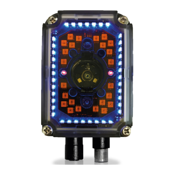
Page 211: Mlt-Dpm Illuminator
MLT-DPM Illuminator MLT-DPM Illuminator This is both a Bright Field and a Dark Field illuminator available for 1.3 MP models. Figure 95 - 39/24-LED MLT-DPM Illuminator The MLT-DPM illuminator is made up of 63 LEDs divided into two groups of four sectors each, independently controlled by the software application. - Page 212 By enabling multiple Image Settings, each having a different ON/OFF LED combination, different consecutive images can be acquired, changing the activation of the eight LED sectors. This feature is particularly effective for reading codes printed/marked on reflective surfaces, by sequentially turning OFF the single LED sectors. Matrix 300N...
-
Page 213: Examples For Dpm Applications
MLT-DPM Illuminator Examples for DPM Applications In the example below, two Data Matrix codes etched onto a plastic reflective surface must be read. With all four LED sectors enabled (Example A), the code is not readable due to the LED reflections on the code surface. With different Image Settings in which the Bottom-Right sector is turned off (removed from the parameter combination - Example B) and the Top-Left sector is turned off (removed from the parameter combination - Example C), the code is illuminated by the other LED sectors... - Page 214 When using the MLT-DPM Central LED Group (Dark Field), the photometric parameters (Exposure time and Gain) are set to lower values in order to obtain results similar to the Diffused Red Illuminator Central LED Group (Bright Field). NOTE Figure 98 - MLT-DPM Central LED Group Matrix 300N...
-
Page 215: Polarized Illuminators
Figure 99 - (left) 1.3 MP model with 8-LED Polarized Illuminator (right) 2 MP model with 10-LED Polarized Illuminator Matrix 300N also comes with a built-in polarizing filter. This is the ideal solution to reduce hot spots on reflective surface applications, such as: •... - Page 216 Illuminators DPM: Data Matrix and QR codes on metal surfaces Non polarized Polarized Matrix 300N...
- Page 217 Polarized Illuminators Bar Code under plastic film Non polarized Polarized Bar Code on glossy surfaces Non polarized Polarized If no polarized illuminator is used, the user may avoid LED reflections by turning on either the Even or the Odd Chain according to the code position in the reader’s Field of View.
-
Page 218: Direct Part Marking Applications
For QR codes the parameter allows the Dot Peen Decoding algorithm to be selected, which improves the decode rate for low quality Direct Part Mark codes and in general for Direct Part Mark codes with dot peening type module shapes. Matrix 300N... -
Page 219: Matrix 300N Recommended Illumination For Dpm
Matrix 300N Recommended Illumination for DPM Matrix 300N Recommended Illumination for DPM In the following table these macro-cases are listed, each of them highlighting the most suitable Matrix 300N lighting system used to resolve the application. Application STD. STD. Diff. -
Page 220: Illumination Examples For Dpm Applications
“Lighting System Working Distances” on page 207. NOTE Illumination Examples for DPM Applications The following images have been captured by a Matrix 300N DPM model reader to demonstrate positioning and contrast considerations for DPM applications. Code Positioning with Respect to Illumination... -
Page 221: Color Contrast Considerations For Dpm Applications
Matrix 300N Recommended Illumination for DPM Color Contrast Considerations for DPM Applications Matrix 300N DIF / MLT-DPM models are available in Red and Blue Light versions to help resolve applications that have colored codes and/or backgrounds. The choice between the blue or red illuminator should be done in order to maximize the contrast between the code and its background;... - Page 222 Red-printed code on dark background Black-printed code on red background Blue-printed code on light background White-printed code on blue background Blue-printed code on dark background Black-printed code on blue background Legend: Suggested Lighting System Compatible Lighting System Lighting System Not Recommended Matrix 300N...
-
Page 223: Lighting System Working Distances
Lighting System Working Distances Lighting System Working Distances Reader Model Lighting System Working Distance Matrix 300N 41x-010 Red Wide 20 to 550 mm Matrix 300N 45x-010 White Wide 20 to 550 mm Matrix 300N 47x-010 Diffused Red, both LED Groups... -
Page 224: Matrix 300N 2Mp Illumination Guidelines
Recommended Consider Consider •STANDARD •STANDARD models for marking and marking and Red Wide Red Medium Angle Angle surface type surface type applications a. For more details, please refer to “Matrix 300N Recommended Illumination for DPM” on page 203. Matrix 300N... -
Page 225: Maintenance
Chapter 9 Maintenance Cleaning Clean the lens cover periodically for continued correct operation of the reader. See General View. Dust, dirt, etc. on the lens cover may alter the reading performance. Repeat the operation frequently in particularly dirty environments. Use soft material and alcohol to clean the lens cover and avoid any abrasive substances. -
Page 226: Troubleshooting
When wiring the device, pay careful attention to the signal name (acronym) on the CBX100/500 spring clamp connectors (Chapter 4). If you are con- necting directly to the Matrix 300N M12 17-pin connector, pay attention to the pin number of the signals (Appendix 12). - Page 227 General Guidelines Troubleshooting Guide Problem Suggestion Check if you are referring to the 17-pin connector or to the CBX spring clamp connectors. Is the sensor connected to Input 1 or Input 2? Is power supplied to the photo sensor? One Shot or Phase For NPN configuration, is power supplied to one of the two I1 or Mode using the Input I2 signals (A or B)?
- Page 228 Run the Rapid Configuration procedure in Chapter 1. Position the reader as described in "Mounting And Position- ing Matrix 300N" on page 57 and through DL.CODE: Tune the Acquisition Delay on Trigger if the moving code is out of the reader field of view;...
-
Page 229: Technical Features
Chapter 11 Technical Features Electrical Features Electrical Features 4xx-01x models Power 4xx-04x models 7xx-01x models Supply Voltage 10 to 30 Vdc PoE Device 48 Vdc Consumption 0.7 to 0.2 A 0.13 W max Communication Interfaces Main: RS232, RS422 Full-duplex 2400 to 115200 bit/s Auxiliary: RS232 2400 to 115200 bit/s ID-NET... -
Page 230: Optical Features
4x2-0xx models = 9 mm 4x3-0xx models = 9 mm 7x2-0xx models = 9 mm 4x4-0xx models = 12 mm 7x6-0xx models = 16 mm 4x5-0xx models = 16 mm Lighting System Internal Illuminator Aiming System Laser Pointers Matrix 300N... -
Page 231: Environmental Features
Environmental Features Environmental Features Environmental Features 0 to 50 C (32 to 122 °F) Operating Temperature for liquid lens models: 0 to 45 °C (32 to 113 °F) -20 to 70 C (-4 to 158 °F) Storage Temperature Max. Humidity 90% non condensing Vibration Resistance 14 mm @ 2 to 10 Hz;... -
Page 232: Software Features
Code Quality Metrics Standard Supported Symbologies ISO/IEC 16022 Data Matrix ECC 200 ISO/IEC 18004 QR Code AIM DPM Data Matrix ECC 200, QR Code ISO/IEC 15416 Code 128, Code 39, Interleaved 2 of 5, Codabar, Code 93, EAN-8-13, UPC-A/E Matrix 300N... -
Page 233: User Interface
User Interface User Interface LED Indicators Power, Ready, Good; Trigger, Com, Status, (Ethernet Network); Good Read (Green Spot), No Read (Red Spot) Keypad Button Configurable via DL.CODE Beeper Configurable via DL.CODE Product Reference Guide... -
Page 234: Alternative Connections
Power, Com and I/O Connector The Matrix 300N reader is equipped with an M12 17-pin male connector for connection to the power supply, serial interfaces and input/output signals. The details of the connector pins are indicated in the following table:... -
Page 235: On-Board Ethernet Connector
On-Board Ethernet Connector Power, Com and I/O Connector Pinout Name Description Auxiliary RS232 RX Auxiliary RS232 TX ID-NET network data + ID-NET network data - Name RS232 RS422 Full-Duplex Main Interface *RX+ (SW Selectable) *RX- RS422 Full Duplex Interface" on page 66 * Do not leave floating, see "... -
Page 236: Power Over Ethernet (Poe) Models
RX- / DC+ Receive data (-) DC power (+) Matrix 300N PoE models only accept Alternative A (power over RJ45 pins 1, 2, 3, 6), Class 0 power levels. Use an Endspan or Midspan PSE device that supports this configuration (i.e. - Page 237 On-Board Ethernet Connector Figure 92 - Matrix 300N PoE PSE Midspan Alternative A Connections OK Figure 93 - Matrix 300N PoE PSE Endspan Alternative B Connections NOT SUPPORTED Figure 94 - Matrix 300N PoE PSE Midspan Alternative B Connections NOT SUPPORTED...
-
Page 238: Id-Net Network Termination
Alternative Connections For Matrix 300N PoE models, the internal Digital Output circuitry is not powered and supply power is not available to any Input/Output devices (Vdc=0). Only input device signals can be accepted directly on the M12 17-pin connector without power. -
Page 239: Outputs
Outputs Outputs Three general purpose non opto-isolated but short circuit protected outputs are available on the M12 17-pin connector. The pinout is the following: Output Pinout Name Description Configurable digital output 1 Configurable digital output 2 Configurable digital output 3 Output reference signal The electrical features of the three outputs are the following: Reverse-Polarity and Short-Circuit Protected... - Page 240 CAUTION Figure 97 - Push-Pull Output Connection For Matrix 300N PoE models, the internal Digital Output circuitry is not powered and supply power is not available to any Input/Output devices (Vdc=0). Only input device signals can be accepted directly on the M12 17-pin connector without power.
-
Page 241: User Interface - Serial Host
User Interface - Serial Host User Interface - Serial Host RS232 PC-side Connections 9-pin male connector 25-pin male connector Name Name How To Build A Simple Interface Test Cable: The following wiring diagram shows a simple test cable including power, exter- nal (push-button) trigger and PC RS232 COM port connections. -
Page 242: Glossary
On an addressable boundary, eight adjacent binary digits (0 and 1) combined in a pattern to represent a specific character or numeric value. Bits are numbered from the right, 0 through 7, with bit 0 the low-order bit. One byte in memory can be used to store one ASCII character. Matrix 300N... - Page 243 Glossary Composite Symbologies Consist of a linear component, which encodes the item's primary data, and an adjacent 2D composite component, which encodes supplementary data to the linear component. Dark Field Illumination Lighting of surfaces at wide angles used to avoid direct reflection of the light into the reader’s lens.
- Page 244 Multi-row (or Stacked) Symbologies Symbologies where a long symbol is broken into sections and stacked one upon another similar to sentences in a paragraph. Random Access Memory. Data in RAM can be accessed in random order, and quickly written and read. Matrix 300N...
- Page 245 Glossary Symbol Verification The act of processing a code to determine whether or not it meets specific requirements. Transmission Control Protocol/Internet Protocol (TCP/IP) A suite of standard network protocols that were originally used in UNIX environ- ments but are now used in many others. The TCP governs sequenced data; the IP governs packet forwarding.
- Page 248 Datalogic S.p.A. and/or its affiliates • Datalogic and the Datalogic logo are registered trademarks of Datalogic S.p.A.