Table of Contents
Advertisement
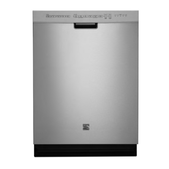
2013 Stainless Steel Tall Tub Dishwashers
665.12762K310
665.12772K310
665.12782K310
665.12803K310
Confidential - Sears Internal Technical Reference Material
Do Not Distribute to Anyone Other Than A Sears Associate
© 2013 Sears, Roebuck & Co.
Printed in U.S.A.
Kenmore Elite
Model Numbers:
665.12763K310
665.12773K310
665.12783K310
665.12764K310
665.12774K310
665.12789K310
Manual No. 22110313
665.12769K310
665.12779K310
665.12793K310
Advertisement
Table of Contents
Troubleshooting

Related Manuals for Sears Elite 665.12762K310


Summary of Contents for Sears Elite 665.12762K310
- Page 1 Model Numbers: 665.12762K310 665.12763K310 665.12764K310 665.12769K310 665.12772K310 665.12773K310 665.12774K310 665.12779K310 665.12782K310 665.12783K310 665.12789K310 665.12793K310 665.12803K310 Confidential - Sears Internal Technical Reference Material Do Not Distribute to Anyone Other Than A Sears Associate © 2013 Sears, Roebuck & Co. Printed in U.S.A.
- Page 2 • Successfully troubleshoot and diagnose malfunctions. • Successfully perform necessary repairs. • Successfully return the product to its proper operational status. Sears Brands Management Corporation assumes no responsibility for any repairs made on our products by anyone other than Authorized Factory Service Technicians. Copyright © 2013, Sears Brands Management Corporation Kenmore Elite 2013 Tall Tub Stainless Steel Dishwasher...
-
Page 3: Table Of Contents
TABLE OF CONTENTS Kenmore Elite 2013 Stainless Steel Tall Tub Dishwasher SECTION 1 — GENERAL INFORMATION DISHWASHER SAFETY .........................1-2 BEFORE USING YOUR DISHWASHER ....................1-3 MODEL & SERIAL NUMBER LABEL .....................1-4 TECH SHEET LOCATION ........................1-4 PRODUCT SPECIFICATIONS ........................1-5 PARTS & FEATURES ..........................1-6 SECTION 2 —... - Page 4 TABLE OF CONTENTS (CONTINUED) SECTION 5 — TESTING SAFETY WARNINGS ..........................5-2 WIRING DIAGRAM ..........................5-3 CONTROL BOARD INFORMATION/SPECS ..................5-4 COMPONENT TESTING ........................5-4 ELECTRONIC CONTROL BOARD ......................5-5 GENERAL THEORY OF OPERATION .....................5-6 POWER CHECK ............................5-6 DOOR SWITCH CIRCUIT ........................5-7 FILL CIRCUIT ............................5-8 DISPENSER CIRCUIT ..........................5-9 WATER HEATING / HEAT DRY ......................5-10 WATER SENSING WITH OWI SENSOR ....................5-11...
-
Page 5: Section 1 - General Information
GENERAL INFORMATION Section 1: General Information This section provides general safety, parts, and information for the “Kenmore Elite Stainless Steel Tall Tub Dishwasher.” ■ Dishwasher Safety ■ Before Using Your Dishwasher ■ Model & Serial Number Label ■ Tech Sheet Locations ■... -
Page 6: Dishwasher Safety
GENERAL INFORMATION Dishwasher Safety Your safety and the safety of others are very important. We have provided many important safety messages in this manual and on your appliance. Always read and obey all safety messages. This is the safety alert symbol. This symbol alerts you to potential hazards that can kill or hurt you and others. -
Page 7: Before Using Your Dishwasher
GENERAL INFORMATION Before Using Your Dishwasher GROUNDING INSTRUCTIONS • For a grounded, cord-connected dishwasher: The dishwasher must be grounded. In the event of a malfunction or breakdown, grounding will reduce the risk of electric shock by providing a path of least resistance for electric current. -
Page 8: Model & Serial Number Label
GENERAL INFORMATION Model & Serial Number Label Model & Serial Number Label Location Tech Sheet Location Tech Sheet Location (Behind Toe Kick Panel) Kenmore Elite 2013 Stainless Steel Tall Tub Dishwasher... -
Page 9: Product Specifications
GENERAL INFORMATION Product Specifications DISHASHER SPECIFICATIONS Line Voltage: 120V AC Frequency: 60 Hz Amps: Low Volts Power Supply: +15V, +13V, +5V, +3.3 Water Pressure: 120 psi Max, 20 psi Min Supply Water Temperature: Minimum - 120° F (49° C) Control: Electronic Control w/Integrated VSM Control Wash Motor: 3-Phase Variable Speed Motor (VSM) -
Page 10: Parts & Features
GENERAL INFORMATION Parts & Features Kenmore Elite 2013 Stainless Steel Tall Tub Dishwasher... - Page 11 CONSUMER INFORMATION Section 2: Consumer Information This section provides consumer troubleshooting information for the “Kenmore Elite Stainless Steel Tall Tub Dishwasher.” Kenmore Elite 2013 Stainless Steel Tall Tub Dishwasher...
- Page 12 CONSUMER INFORMATION Consumer Troubleshooting Kenmore Elite 2013 Stainless Steel Tall Tub Dishwasher...
- Page 13 CONSUMER INFORMATION Consumer Troubleshooting (continued) Kenmore Elite 2013 Stainless Steel Tall Tub Dishwasher...
-
Page 14: Notes
CONSUMER INFORMATION Consumer Troubleshooting (continued) Notes Kenmore Elite 2013 Stainless Steel Tall Tub Dishwasher... -
Page 15: Section 3 - Component Access
COMPONENT ACCESS Section 3: Component Access This section provides service parts access, removal, and installation instructions for the “Kenmore Elite Stainless Steel Tall Tub Dishwasher.” ■ Insulation Blanket ■ Removing Door Latch Strike ■ Door Spring Adjustment ■ Water Inlet & Drain Hose ■... - Page 16 COMPONENT ACCESS Insulation Blanket and Door Latch Strike Removing Door Latch Strike WARNING (FID and 2 ½” Console) 1. Open the dishwasher door. 2. Depress the 2 outside bars and pull out the latch, see figures 1, 2 and 3. Electrical Shock Hazard Disconnect power before servicing.
-
Page 17: Door Spring Adjustment
COMPONENT ACCESS Adjustable Door Springs, Wheels, Water Inlet and Drain Hose Water Inlet and Drain Hose WARNING Drain loop must be higher than drain to prevent siphoning. Drain Hose Loop Inlet Hose Electrical Shock Hazard Disconnect power before servicing. Replace all parts and panels before operating. Failure to do so can result in death or Water Inlet electrical shock. -
Page 18: Overfill Assembly
COMPONENT ACCESS Overfill Assembly WARNING Accessing Overfill Assembly Electrical Shock Hazard Disconnect power before servicing. Replace all parts and panels before operating. Failure to do so can result in death or electrical shock. Overfill Assembly Components Figure 2 - Location of Overfill Assembly 1. -
Page 19: Accessing Door Components
COMPONENT ACCESS Accessing Door Components 3. Remove the outer door panel, see figure 3. WARNING Electrical Shock Hazard Disconnect power before servicing. Replace all parts and panels before operating. Failure to do so can result in death or electrical shock. Removing Door Panel Figure 3 1. -
Page 20: Removing User Interface
COMPONENT ACCESS Removing User Interface WARNING Control Board and User Interface Electrical Shock Hazard Disconnect power before servicing. Replace all parts and panels before operating. Failure to do so can result in death or electrical shock. 1. Unplug dishwasher or disconnect power. 2. -
Page 21: Removing Latch Assembly
COMPONENT ACCESS Removing Latch Assembly 4. Remove latch assembly from door. See figure 3. WARNING 5. Disconnect harness assembly. Electrical Shock Hazard Disconnect power before servicing. Replace all parts and panels before operating. Failure to do so can result in death or electrical shock. -
Page 22: Removing Electronic Control Board
COMPONENT ACCESS Removing Electronic Control Board 4. Slide the electronic control to the left to unhook the tabs WARNING on the back of the control from the slots in the door bracket, see figures 2 and 3. Electrical Shock Hazard Disconnect power before servicing. -
Page 23: Removing Dispenser Assembly
COMPONENT ACCESS Removing Dispenser Assembly WARNING Dispenser Assembly Electrical Shock Hazard Disconnect power before servicing. Replace all parts and panels before operating. Failure to do so can result in death or electrical shock. 1. Unplug dishwasher or disconnect power. 2. Remove the outer panel from the door. 3. -
Page 24: Spray Arms, Feed Tube, And Manifold
COMPONENT ACCESS Spray Arms, Feed Tube, and Manifold Feed tube Third level spray arm Manifold TurboZone Manifold Upper spray arm Component Identification 3-10 Kenmore Elite 2013 Stainless Steel Tall Tub Dishwasher... -
Page 25: Tub Components - Stainless Steel Tub Models
COMPONENT ACCESS Tub Components – Stainless Steel Models TurboZone ® Manifold (available on some models) 360° Rotational Feed Tube to Middle and Lower Spray Arm Upper Spray Arms Water Inlet Lower Filter Upper Filter Lower Spray Arm Sensor Inset 120VAC Heater Water Level Float Tub Component Identification (TurboZone and Controlled Lower Spray Arm &... -
Page 26: Removing The Upper Rack(S)
position and level. and top r in the low Top Rack To remo COMPONENT ACCESS 1. To ac rack Removing the Upper Rack(s) clicks 2. To op Removable Top Rack (for SatinGlide rails) ® Removing The Upper Rack Removing The Upper Rack track The removable top rack allows you to wash larger items such as 3. -
Page 27: Removing Lower Spray Arm
COMPONENT ACCESS Removing Lower Spray Arm To remove the lower spray arm: 3. Lift off, see figure 3. 1. Lower spray arm nut location, see figure 1. Figure 1 Figure 3 Lower Spray Arm Assembly 2. Rotate the lower spray arm nut ¼ turn counter clockwise to remove the spray arm, see figure 2. -
Page 28: Removing Filters
COMPONENT ACCESS Removing Filters To remove the filters: UltraClean® Filtration System 1. Upper Filter-Push down and turn filter 1/4 turn counterclockwise and lift out, see figures 1 and 2. Upper Filter Assembly Lower Filter Figure 4 - Filtration System Figure 1 Figure 2 2. - Page 29 COMPONENT ACCESS Removing TurboZone Manifold and Diverter Disk ® To Remove TurboZone® Manifold: Accessing Diverter Disk (available on some models) (stainless steel tub) 1. Unsnap manifold from distribution tube. 1. Unsnap distribution tube from tub clips. See figures 1 & 2. 2.
-
Page 30: Removing Diverter Disk
COMPONENT ACCESS Removing Diverter Disk (continued) 3. Release the lock on the diverter housing, see figure 4. 5. Lift out the housing, see figure 6. Figure 4 Figure 6 4. Rotate the housing counterclockwise, see figure 5. Diverter Disk 6. The diverter disc attaches to a keyed shaft, see figure 7. Figure 5 Figure 7 continued next page . - Page 31 COMPONENT ACCESS Removing Diverter Disk (continued) 7. Lift off the disc, see figures 8 and 9. Installing Diverter Housing 1. Align the arrow on the diverter housing to the lower arrow on the sump. 2. Rotate the housing clock wise until the diverter housing locks in place, see figure 1.
-
Page 32: Under The Tub Components
COMPONENT ACCESS Under the Tub Components Fill Valve Overfill/Float Valve VS Drain Motor Junction Box Lower Spray Arm Motor Lower Spray Arm Sensor OWI / NTC Diverter Motor & Switch Adjustable Heater Wheels VS Wash Motor Figure 1 3-18 Kenmore Elite 2013 Stainless Steel Tall Tub Dishwasher... -
Page 33: Heater
COMPONENT ACCESS Heater Heater Connection Heater Connection Figure 1 Heater Components A. Heater Element Assembly B. Rubber Washer C. Heater Element Nut D. Speed Nut E. Heater Probe Shield Figure 2 Kenmore Elite 2013 Stainless Steel Tall Tub Dishwasher 3-19... -
Page 34: Removing Sump Assembly & Drain Pump
COMPONENT ACCESS Removing Sump Assembly & Drain Pump 3. Remove the wire harness from the bracket on the side of WARNING the sump and move off to the side, see figures 3 and 4. Electrical Shock Hazard Disconnect power before servicing. Replace all parts and panels before operating. - Page 35 COMPONENT ACCESS Removing Sump Assembly & Drain Pump (continued) 5. Rotate the drain pump 1/4 turn counter clockwise, see figure 6. Figure 6 Figure 9 - Locked 6. Remove the drain pump, see figure 7. Figure 10 - Unlocked Figure 7 8.
- Page 36 COMPONENT ACCESS Removing Sump Assembly & Drain Pump (continued) 9. Tilt the assembly and lift out to remove, see figures 12. 11. Unplug the diverter motor harness, see figure 16. NOTE: Also disconnect the lower spray arm motor harness on models that have the controlled lower spray arm. Figure 12 NOTE: When installing the sump assembly, align the tab on the assembly with the slot in the tub, see figures 13 and 14.
-
Page 37: Removing Optical Water Indicator
COMPONENT ACCESS Removing Optical Water Indicator 1. Rotate optical water indicator counter-clockwise 1/4 turn, WARNING see figure 3. Electrical Shock Hazard Disconnect power before servicing. Replace all parts and panels before operating. Failure to do so can result in death or electrical shock. -
Page 38: Removing Diverter Assembly
COMPONENT ACCESS Removing Diverter Assembly 3. Remove 2 Torx screws, see figure 2. (Diverter assembly WARNING shown without lower wash arm motor.) Remove 2 #10 Torx screws Electrical Shock Hazard Disconnect power before servicing. Replace all parts and panels before operating. Failure to do so can result in death or electrical shock. -
Page 39: Removing Lower Spray Arm Sensor
COMPONENT ACCESS Removing Lower Spray Arm Sensor Controlled Spray Arm Shaft and Sensor WARNING Controlled Spray Arm Shaft Electrical Shock Hazard Disconnect power before servicing. Replace all parts and panels before operating. Failure to do so can result in death or electrical shock. -
Page 40: Wash Motor Replacement
COMPONENT ACCESS Wash Motor Replacement Steps for Removing Old Wash Motor 2. Remove old clamps, see figure 3. WARNING Electrical Shock Hazard Disconnect power before servicing. Replace all parts and panels before operating. Failure to do so can result in death or electrical shock. - Page 41 COMPONENT ACCESS Steps for Removing Old Wash Motor (continued) 4. Pry up on old seal, see figure 5. 5. Remove seal, see figure 6. Figure 5 Figure 6 Motor and Sump Assembly Isolator Grommet Hose Assembly (includes 2 clamps) Wash Motor Latch &...
- Page 42 COMPONENT ACCESS Steps for Installing New Wash Motor 3. Seat new seal, see figure 3. WARNING Electrical Shock Hazard Disconnect power before servicing. Replace all parts and panels before operating. Failure to do so can result in death or electrical shock. 1.
- Page 43 COMPONENT ACCESS Steps for Installing New Wash Motor (continued) 5. Wash motor hose and clamps, see figure 5. 7. Align tabs and tighten clamps, see figures 7 and 8. Figure 5 6. Install clamps with screws toward bottom, see figure 6. Figure 7 Figure 6 Figure 8...
-
Page 44: Notes
COMPONENT ACCESS Notes 3-30 Kenmore Elite 2013 Stainless Steel Tall Tub Dishwasher... -
Page 45: Section 4 - Diagnostics & Troubleshooting
DIAGNOSTICS & TROUBLESHOOTING Section 4: Diagnostics & Troubleshooting This section provides diagnostic, fault codes, and troubleshooting information for the “Kenmore Elite Stainless Steel Tall Tub Dishwasher.” ■ Safety First ■ Wash Cycles ■ Service Diagnostic Cycle ■ Service Diagnostic Cycle Notes ■... - Page 46 DIAGNOSTICS & TROUBLESHOOTING For Service Technician Use Only WARNING DANGER Electrical Shock Hazard Electrical Shock Hazard Only authorized technicians should perform Disconnect power before servicing. diagnostic voltage measurements. Replace all parts and panels before operating. After performing voltage measurements, Failure to do so can result in death or disconnect power before servicing.
- Page 47 DIAGNOSTICS & TROUBLESHOOTING For Service Technician Use Only Wash Cycles Normal Cycle (NOTE: Each sequence box contains multiple intervals.) DRAIN FILL WASH DETER- WASH THERMAL WASH DRAIN FILL WASH DRAIN FILL 0 MIN, 0:55 6:50 GENT 2:30 HOLD (1,2) 20:00- SEQUENCE 0:18 1:47...
- Page 48 DIAGNOSTICS & TROUBLESHOOTING For Service Technician Use Only Kenmore Elite 2013 Stainless Steel Tall Tub Dishwasher...
-
Page 49: Service Diagnostic Cycle Notes
DIAGNOSTICS & TROUBLESHOOTING For Service Technician Use Only Service Diagnostic Cycle Notes Interval 10 (4 Min. Lower Wash) Diagnostic Details: 1. To invoke the diagnostics cycle, perform the following key presses while in standby. NOTE: Lower Spray Arm (LSA) motor and sensor status •... -
Page 50: Service Diagnostics With Error Codes
DIAGNOSTICS & TROUBLESHOOTING For Service Technician Use Only Service Diagnostics With Error Codes Entry Sequence: To invoke the diagnostics cycle, perform the following key presses while in standby. Press any 3 keys in the sequence 1-2-3, 1-2- 3, 1-2-3 with no more than 1 second between key presses. NOTE: Some models have replaced the “Clean” LED with “Complete.” Kenmore Elite 2013 Stainless Steel Tall Tub Dishwasher... -
Page 51: Service Error Codes
DIAGNOSTICS & TROUBLESHOOTING For Service Technician Use Only Service Error Codes #1 FUNCTION PROBLEM CAUSES WHAT TO CHECK CODE CODE 1 - CONTROL 1-PILOT CONTROL DETECTED K400 PILOT RELAY STUCK 1. UNPLUG DISHWASHER OR DISCONNECT POWER. CLOSED. STUCK ON 2. CHECK ALL LOADS ON K400 PILOT RELAY FOR SHORTS. 3. - Page 52 DIAGNOSTICS & TROUBLESHOOTING For Service Technician Use Only Service Error Codes #2 FUNCTION PROBLEM CAUSES WHAT TO CHECK CODE CODE 3-THERMISTOR/ 3-FAILED OWI FAILURE 1. UNPLUG DISHWASHER OR DISCONNECT POWER. CALIBRATION 2. REMOVE OWI AND CHECK LENS SURFACE. LENS SHOULD BE CLEAR AND SURFACE SHOULD BE FREE OF DEBRIS AND SCRATCHES.
- Page 53 DIAGNOSTICS & TROUBLESHOOTING For Service Technician Use Only Service Error Codes #3 FUNCTION PROBLEM CAUSES WHAT TO CHECK CODE CODE 6-INLET 1-LOW/NO FILL VALVE OR WATER LINE PLUGGED WITH TURN OFF WATER SUPPLY TO DISHWASHER DISCONNECT WATER, DEBRIS. LINE TO INLET VALVE AND INSPECT/CLEAN THE INLET SCREEN OF WATER WATER FILL VALVE AND RECONNECT WATER.
- Page 54 DIAGNOSTICS & TROUBLESHOOTING For Service Technician Use Only Service Error Codes #4 FUNCTION PROBLEM CAUSES WHAT TO CHECK CODE CODE 6-INLET 6-COOL INCOMING WATER UNDER 18 C/65°F. 1. BE SURE DISHWASHER IS CONNECTED TO THE HOT WATER SUPPLY. WATER WATER 2.
- Page 55 DIAGNOSTICS & TROUBLESHOOTING For Service Technician Use Only Service Error Codes #5 FUNCTION PROBLEM CAUSES WHAT TO CHECK CODE CODE 9-DIVERTER 3-DIVERTER CONTROL DETECTED DIVERTER DISK IN SUMP IS REMOVE LOWER SPRAY ARM, TURBO ZONE ASSEMBLY, REAR FEED MISSING. TUBE AND OUTLET COVER AND VERIFY THE ROUND DIVERTER DISK DISC IS INSTALLED.
-
Page 56: Troubleshooting Guide
DIAGNOSTICS & TROUBLESHOOTING For Service Technician Use Only Troubleshooting Guide #1 NOTES: ■ For resistance checks, refer to the “Dishwasher Strip Circuits” section. ■ For checking operation with diagnostics, refer to “Service Diagnostics Cycle” section. ■ For information on Normal Cycle, 1-Hour Cycle, and Pots & Pans Cycle, See “Wash Cycle Operation” section. CUSTOMER POTENTIAL CAUSES CHECK... - Page 57 DIAGNOSTICS & TROUBLESHOOTING For Service Technician Use Only Troubleshooting Guide #2 CUSTOMER POTENTIAL CAUSES CHECK RELATED DESCRIPTION ERROR CODES ONE OR MORE KEYS WON’T STUCK KEY / SHORT CIRCUIT(S) IN KEYPAD REFER TO SERVICE ERROR CODES TABLE. RESPOND (BUT SOME KEYS OR IN CONTROL’S INPUT LINES THAT READ WORK) THE KEYS.
- Page 58 DIAGNOSTICS & TROUBLESHOOTING For Service Technician Use Only Troubleshooting Guide #3 CUSTOMER POTENTIAL CAUSES CHECK RELATED DESCRIPTION ERROR CODES WILL NOT DRAIN OR DRAIN LOOP CHECK VALVE NOT SEALING. 1. DISCONNECT DRAIN HOSE AT PLUMBING CONNECTION. EXCESS WATER LEFT IN 2.
- Page 59 DIAGNOSTICS & TROUBLESHOOTING For Service Technician Use Only Troubleshooting Guide #4 CUSTOMER POTENTIAL CAUSES CHECK RELATED DESCRIPTION ERROR CODES POOR WASH HEATING PROBLEM REFER TO SERVICE ERROR CODES TABLE. SOFTENER PROBLEM REFER TO SERVICE ERROR CODES TABLE. (ONLY SOME MODELS) FILM OR SPOTS ON GLASSES CUSTOMER NOT USING RINSE AID AND/OR CHECK RINSE AID GAGE LEVEL ON DISPENSER;INSTRUCT...
- Page 60 DIAGNOSTICS & TROUBLESHOOTING For Service Technician Use Only Troubleshooting Guide #5 CUSTOMER POTENTIAL CAUSES CHECK RELATED DESCRIPTION ERROR CODES MELTED DISHWARE AND/ CUSTOMER USES NON-DISHWASHER SAFE INSTRUCT CUSTOMER. OR SPRAY ARM AND/OR DISHES OR LOADS PLASTIC DISHES DIRECTLY DISHWASHER ALWAYS HOT OVER HEATER.
-
Page 61: Section 5 - Testing
TESTING Section 5: Testing This section provides a wiring diagram, control board specifications, testing procedures and strip circuits the “Kenmore Elite Stainless Steel Tall Tub Dishwasher.” ■ Dishwasher Safety ■ Wiring Diagram ■ Control Board Information ■ General Theory of Operation ■... - Page 62 TESTING For Service Technician Use Only WARNING DANGER Electrical Shock Hazard Electrical Shock Hazard Only authorized technicians should perform Disconnect power before servicing. diagnostic voltage measurements. Replace all parts and panels before operating. After performing voltage measurements, Failure to do so can result in death or disconnect power before servicing.
- Page 63 TESTING Kenmore Elite 2013 Stainless Steel Tall Tub Dishwasher...
-
Page 64: Control Board Information/Specs
TESTING For Service Technician Use Only TRIAC FUSE DIAGNOSTICS: DANGER TRIAC LOADS: DISPENSER, DIVERTER MOTOR, FILL VALVE, LOWER SPRAY ARM (SOME MODELS) ¾ If any of the TRIAC loads work, then the TRIAC fuse is OK. Diagnose and repair non-working triac loads. ¾... -
Page 65: Electronic Control Board
TESTING For Service Technician Use Only ELECTRONIC CONTROL BOARD CONTROL ASSEMBLY PUSH TO RELEASE AND ROTATE (ROTATE) CONTROL PANEL SNAP LOCKS CONTROL IN PLACE CONTROL BOX CONTROL BRACE TO REMOVE, PINCH ARMS AND ROTATE 4 ARMS BUTTONS ON BOTTOM OF CONTROL HOUSING SLIDE INTO KEYHOLE SLOTS ON CONTROL PANEL TO SUPPORT THE CONTROL. -
Page 66: General Theory Of Operation
TESTING For Service Technician Use Only Power Check DANGER This test checks for incoming and outgoing power to and from the control board. This test assumes that proper voltages is present at the outlet or direct connect cable. Test Procedure 1. -
Page 67: Door Switch Circuit
TESTING For Service Technician Use Only 4. Check door switch contacts and all connections in the DANGER door switch circuit. Visually check that the P9 connector on the control and the door latch connector are securely installed. ¾ If visual check passes, go to step 5. ¾... -
Page 68: Fill Circuit
TESTING For Service Technician Use Only 4. Remove outer door panel to access control board. DANGER 5. Unplug connector P6 from control board. 6. Check the fill valve and harness—using an ohmmeter, measure the resistance between P6-4 and P6-6. ¾ If the resistance is between 890-1090 ohms, the fill valve and harness are good. -
Page 69: Dispenser Circuit
TESTING For Service Technician Use Only 4. Remove outer door panel to access control board. DANGER 5. Unplug connector P9 from control board. 6. Check the dispenser solenoid or wax motor (depending on model) and harness—using an ohmmeter, measure the resistance between P9-1 and P9-3. -
Page 70: Water Heating / Heat Dry
TESTING For Service Technician Use Only 4. Using an ohmmeter, measure resistance between P4, pins DANGER 3 and 4. ¾ If the resistance is between 8-30 ohms, go to step 6. ¾ If an open circuit is detected, go to step 5. 5. -
Page 71: Water Sensing With Owi Sensor
TESTING For Service Technician Use Only DANGER TEMP °F (°C) RES RANGE k ohms 77° F (25° C) 46 – 52k ohms 140° F (60° C) 11 – 13k ohms NOTE: All thermistor resistance measurements must be made while dishwasher is unplugged or disconnected from power and connector P12 removed from control. -
Page 72: Diverter Motor
TESTING For Service Technician Use Only 3. Unplug dishwasher or disconnect power. DANGER 4. Remove outer door panel to access control board. 5. Unplug connector P7 from control board. 6. Check the diverter motor—using an ohmmeter, measure the resistance between P7-4 and P7-6. ¾... -
Page 73: Diverter Sensor/Position Switch
TESTING For Service Technician Use Only 2. If the diverter is diverting the flow of water to the wash DANGER zones, the diverter motor is working–continue to step 3. If not, perform the diverter motor test procedure on the preceding page. 3. -
Page 74: Wash Motor (Variable Speed)
TESTING For Service Technician Use Only 5. Visually check that connector P5 is inserted all the way DANGER into the control board. ¾ If visual checks pass, go to step 6. ¾ If visual checks fail, reconnect P5 and repeat step 2. 6. -
Page 75: Drain Motor (Variable Speed)
TESTING For Service Technician Use Only 5. Visually check that connector P5 is inserted all the way DANGER into the control board. ¾ If visual checks pass, go to step 6. ¾ If visual checks fail, reconnect P5 and repeat step 2. 6. -
Page 76: Vent Wax Motor
TESTING For Service Technician Use Only Test Procedure DANGER 1. Unplug dishwasher or disconnect power. 2. Remove outer door panel to access control board. 3. Unplug connector P10 from control board. 4. Check the vent wax motor and harness—using an ohmmeter, measure the resistance between P10-1 and P10-3. -
Page 77: Vent Fan
TESTING For Service Technician Use Only Test Procedure DANGER 1. Check the vent fan and electrical connections by performing the Service Diagnostic Cycle. The following steps assume that this step was unsuccessful. 2. Unplug dishwasher or disconnect power. 3. Remove outer door panel to access control board. 4. -
Page 78: Lower Spray Arm Motor
TESTING For Service Technician Use Only ¾ YES – check for open door switch, TRIAC fuse, or pilot relay. DANGER ¾ NO – just the spray arm motor. Go to step 4. 4. Unplug dishwasher or disconnect power. 5. Remove outer door panel to access control board. 6. -
Page 79: Lower Spray Arm Sensor
TESTING For Service Technician Use Only Minute 3: LSA Rotates CCW DANGER ¾ Clean LED lit to indicate LSA motor status good. Minute 4: LSA Rotates CW ¾ Clean LED lit to indicate LSA sensor status good. The following steps assume that this step was unsuccessful. 3. -
Page 80: User Interface
TESTING For Service Technician Use Only 4. Disconnect user interface connection from control board. DANGER Verify all other connections to the control are good. 5. Re-assemble door, but do not close door. 6. Plug in dishwasher or reconnect power. 7. Wait at least 7 seconds for control to power-up completely. - Page 82 Manual No. 22110313 Kenmore Elite 2013 Stainless Steel Tall Tub Dishwasher...