Table of Contents
Advertisement
Quick Links
Advertisement
Table of Contents

Related Manuals for Zotac E2-1800-ITX-WiFi Series


Summary of Contents for Zotac E2-1800-ITX-WiFi Series
- Page 2 Electronic Emission Notices WARNING! Federal Communications Commission (FCC) Statement This equipment has been tested and found to comply with the limits for a Class B digital device, pursuant to Part 15 of FCC Rules. These limits are designed to provide reasonable protection against harmful interference in a residential installation.
-
Page 3: Table Of Contents
AMD A68M-ITX series motherboard Table of Contents Motherboard Specifications ------------------------------------------------------------------- 4 Motherboard Layout------------------------------------------------------------------------------ 6 Hardware Installation ---------------------------------------------------------------------------- 11 Safety Instructions ----------------------------------------------------------------------------- 11 Installing Memory Modules ------------------------------------------------------------------ 12 Installing the Motherboard ------------------------------------------------------------------- 13 Installing the I/O Shield ------------------------------------------------------------------ 13 Securing the Motherboard into the Chassis ---------------------------------------- 13 Connecting Cables and Setting Switches ------------------------------------------------ 14 24-pin ATX Power Connector-PW2 (for ATX version) ---------------------------- 15 DC OUT Connector-CN4 (for DC-DC version) ------------------------------------- 16... - Page 4 Table of Contents User Password ----------------------------------------------------------------------------- 30 Exit Menu ---------------------------------------------------------------------------------------- 31 Save Changes and Exit ------------------------------------------------------------------ 31 Discard Changes and Exit -------------------------------------------------------------- 31 Save Changes and Reset --------------------------------------------------------------- 31 Discard Changes and Reset------------------------------------------------------------ 31 Save Changes ----------------------------------------------------------------------------- 32 Discard Changes -------------------------------------------------------------------------- 32 Restore Defaults --------------------------------------------------------------------------- 32 Save as User Defaults ------------------------------------------------------------------- 32 Restore User Defaults -------------------------------------------------------------------- 32...
-
Page 5: Motherboard Specifications
AMD A68M-ITX series motherboard Motherboard Specifications q Chipset v AMD A68M (Hudson-M3L) q Size v Mini ITX form factor of 6.7 inch x 6.7 inch q Microprocessor Support v AMD E2-1800 (dual core, 1.7 GHz) q Operating Systems: v Windows 7 & Windows 8 v 32-bit and 64-bit support q System Memory Support v Two 204-pin DDR3-1333 SO-DIMM slots... - Page 6 Motherboard Specifications q Onboard Audio v 6 channel High Definition Audio v All DACs support 192k/96k/48k/44.1kHz sample rate v Optical SPDIF q Green Function v Supports ACPI (Advanced Configuration and Power Interface) v Suspend to DRAM supported (STR) v RTC timer to power-on the system v AC power failure recovery q Onboard Graphics Support v AMD Radeon HD7340, DirectX11...
-
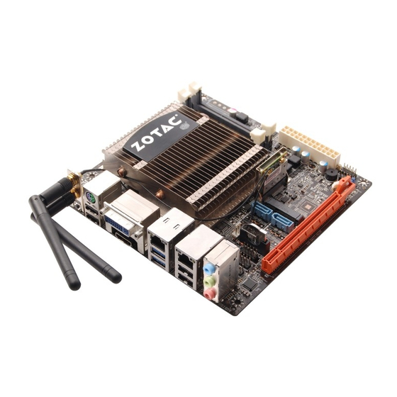
Page 7: Motherboard Layout
AMD A68M-ITX series motherboard Motherboard Layout The motherboard inludes two versions: ATX version and DC-DC version. Users please refer to the corresponding layout picture below. Figure 1 for ATX version: C_FAN1 Chipset LAN/USB3.0 C_FAN2 LAN/USB2.0 SPK1 FP_S1 FP_U1 PCIE2 Figure 1. Board Layout (ATX version) 1. - Page 8 Motherboard layout Figure 2 for DC-DC version: DC_IN C_FAN1 Chipset LAN/USB3.0 C_FAN2 LAN/USB2.0 SPK1 FP_S1 FP_U1 PCIE2 Figure 2. Board Layout (DC-DC version) 1. DC-OUT Connector-CN4 10. COM Header-CN1 2. Speaker Header-SPK1 11. USB 2.0 Header-FP_U1 3. Front Panel Header-FP1 12.
- Page 9 AMD A68M-ITX series motherboard Figure 3. Backpanel Connectors For ATX version For DC-DC version 1. Clear CMOS Button 2. USB 2.0 Ports 3. HDMI Port 4. USB 3.0 Ports 5. Port 2-Channel 4-Channel 6-Channel Blue Line-In Rear Speaker Out Rear Speaker Out Green Line-Out Front Speaker Out...
- Page 10 Rear Panel 6. LAN port LED indicators Activity LED Speed LED Speed LED Activity LED Activity LED Speed LED Status Descritption Status Description No link Speed: 10 Mbps Blinking Data activity Green Speed: 100 Mbps Orange Speed: 1000 Mbps 7. DVI-I Port (single-link DVI-I) 8.
- Page 11 AMD A68M-ITX series motherboard 10. 19V DC Power input (for DC-DC version) This motherboard contains a DC power input jack (as picture 4). Users can plug a 19V AC/ DC adapter to the DC power input jack (as picture 5). Please use a 19V DC power adapter instead of ATX power supply.
-
Page 12: Hardware Installation
Hardware Installation Hardware Installation This section will guide you through the installation of the motherboard. The topics covered in this section are: q Installing Memory Modules q Installing the Motherboard q Connecting Cables and Setting Switches Safety Instructions To reduce the risk of fire, electric shock, and injury, always follow basic safety precautions. Remember to remove power from your computer by disconnecting the AC main source before removing or installing any equipment from/to the computer chassis. -
Page 13: Installing Memory Modules
AMD A68M-ITX series motherboard Installing Memory Modules Your new motherboard has two 1.5V 204-pin slots for SO-DIMM DDR3 memory. These slots support 1GB/2GB/4GB/8GB DDR3 devices. There must be at least one memory bank populated to ensure normal operation. Refer to the following recommendations to install memory modules. Note that a memory module has a notch, so it can only fit in one direction. -
Page 14: Installing The Motherboard
Hardware Installation Installing the Motherboard The sequence of installing the motherboard into the chassis depends on the chassis you are using and if you are replacing an existing motherboard or working with an empty chassis. Determine if it would be easier to make all the connections prior to this step or to secure the motherboard and then make all the connections. -
Page 15: Connecting Cables And Setting Switches
AMD A68M-ITX series motherboard Connecting Cables and Setting Switches This section takes you through all the connectors and switch settings necessary on the motherboard. This will include: q Power Connector v 24-pin ATX Power Connector-PW2 (for ATX version) v DC OUT Connector-CN4 (for DC-DC version) q Internal Headers/Connectors v USB Header-FP_U1 v Speaker Header-SPK1... -
Page 16: 24-Pin Atx Power Connector-Pw2 (For Atx Version)
Hardware Installation 24-pin ATX Power Connector-PW2 (for ATX version) PW2 is the main power supply connector. Make sure that the power supply cable and pins are properly aligned with the connector on the motherboard. Firmly plug the power supply cable into the connector and make sure it is secure. -
Page 17: Dc Out Connector-Cn4 (For Dc-Dc Version)
AMD A68M-ITX series motherboard DC OUT Connector-CN4 (for DC-DC version) This motherboard can supply the power to SATA devices with a SATA power cable. Users can plug a SATA power cable (as picture 7) to the DC out connector (as picture 8). -
Page 18: Usb Header-Fp_U1
Hardware Installation USB Header-FP_U1 This motherboard contains four USB 2.0 ports and two USB 3.0 ports that are exposed on the rear panel of the chassis (Figure 3). The motherboard also contains one 10-pin internal USB 2.0 header onboard. The onboard header are optional. Note: Secure the bracket to either the front or rear panel of your chassis (not all chassis are equipped with the front panel option). -
Page 19: Fp Audio Header-Fp_S1
AMD A68M-ITX series motherboard FP Audio Header-FP_S1 The audio connector supports HD audio standard and provides two kinds of audio output choices: the Front Audio, the Rear Audio. The front Audio supports re-tasking function. FP_S1 Note: FP_S1-Pin Definition In order to utilize the front audio header, Assignment Assignment your chassis must have front audio... -
Page 20: Front Panel Header-Fp1
Hardware Installation Front Panel Header-FP1 The front panel header on this motherboard is one connector used to connect the following four cables: q PWR LED Attach the front panel power LED cable to these two pins of the connector. The Power LED indicates the system’s status. -
Page 21: Connecting Serial Ata Cables (Sata0~1)
AMD A68M-ITX series motherboard Connecting Serial ATA Cables (SATA0~1) The Serial ATA III connector is used to connect the Serial ATA III device to the motherboard. These connectors support the thin Serial ATA III cables for primary storage devices. The current Serial ATA III interface allows up to 6 Gb/s data transfer rate. -
Page 22: Expansion Slots
Hardware Installation Expansion Slots The motherboard contains three expansion slots: one PCI Express x16 slot and two Mini PCI Express slots. PCIE1 Mini PCI Express Slots-J5/8 There are two Mini PCI Express slots. J5 supports one half-sized WiFi card. J8 supports one mSATA SSD. -
Page 23: Jumper Settings
AMD A68M-ITX series motherboard Jumper Settings This chapter explains how to configure the motherboard’s hardware. Before using your computer, make sure all jumpers and DRAM modules are set correctly. Refer to this chapter whenever in doubt. JP1-Clear CMOS Selection 1-2* Normal* Clear CMOS Close Open... -
Page 24: Configuring The Bios
Configuring the BIOS Configuring the BIOS This section discusses how to change the system settings through the BIOS Setup menus. Detailed descriptions of the BIOS parameters are also provided. Enter BIOS Setup The BIOS is the communication bridge between hardware and software. Correctly setting the BIOS parameters is critical to maintain optimal system performance. -
Page 25: X-Setting Menu
AMD A68M-ITX series motherboard q Memory Information Displays the auto-detected memory information. q CPU Information Displays the auto-detected CPU information. q Storage Information Displays the auto-detected SATA port information. q System Language Choose the system default language. q System Date/Time Allows you to set the system date/time. -
Page 26: Advanced Menu
Configuring the BIOS Advanced Menu The Advanced menu items allow you to change the settings for the CPU and other system devices. Press <Enter> to display the configuration options: CPU Configuration The items in this menu show the CPU-related information that the BIOS automatically detects. -
Page 27: Usb Configuration
AMD A68M-ITX series motherboard USB Configuration The items in this menu allow you to change the USB-related features. Press <enter> To display the configuration options: q Legacy USB Support Allows you to enable or disable support for USB devices on legacy operating systems. -
Page 28: Network Stack
Configuring the BIOS Network Stack The item in this menu allows you to set network stack. q Network stack This item allows you to enable or disable UEFI network stack. Realtek PCIe GBE Family Controller The submenu items show driver and device information. PC Health Menu Select PC Health from the BIOS Setup Utility menu to display the System menu. -
Page 29: Powermanage Menu
AMD A68M-ITX series motherboard PowerManage Menu The items in this menu allow you to control the system power management. Press <Enter> to display the configuration options: q Enable ACPI Auto Configuration Enable or disable ACPI auto configuration. q Enable Hibernation Enable or disable hibernation function. -
Page 30: Boot Menu
Configuring the BIOS Boot Menu The Boot menu items allow you to change the system boot options. Press <Enter> to display the configuration options: Boot Settings Configuration The items allow you to configure Boot settings. Press <Enter> To display the configuration options: q Setup Prompt Timeout Use this item to set number of seconds to wait for setup activation key. -
Page 31: Security Menu
AMD A68M-ITX series motherboard q Boot uEFI OS Selection The menu items allow you to select boot OS type, [Legacy OS], and [uEFI OS]. Security Menu The security menu items allow you to change the system security settings. Press <enter> to display the configuration options: Administrator Password Select this item to set Setup Administrator Password. -
Page 32: Exit Menu
Configuring the BIOS Exit Menu The exit menu items allow you to load the option or failsafe default values for the BIOS items, and save or discard your changes to the BIOS items. Press <Enter> to display the sub-menu: Save Changes and Exit Select this item and press <Enter>... -
Page 33: Save Changes
AMD A68M-ITX series motherboard Save Changes Select this item and press <Enter> to save the changes that you have made in the BIOS Setup and exit the BIOS Setup. When the diolog box [Save configuration?] appears, select [Yes] to save changes, or select [No] to return to the main menu. Discard Changes This option allows you to discard the selections you have made and restore the previously saved values. -
Page 34: Flash Update Procedure
Configuring the BIOS FLASH Update Procedure The program EFUDOS.exe is included in the driver disk (X:\Utility\EFUDOS.exe). Please follow the recommended procedure to update the flash BIOS, as listed below. (X: your driver disk letter). 1. Create a DOS-bootable floppy diskette. Copy the new BIOS file (just obtained or downloaded) and the utility program EFUDOS.exe to the diskette. -
Page 35: Installing Drivers And Software
AMD A68M-ITX series motherboard Installing Drivers and Software Note: 1. It is important to remember that before installing the driver disk that is shipped in the kit, you need to load your operating system. The motherboard supports Windows 7 32bit/64bit and Windows 8 32bit/64bit. 2. - Page 36 Installing Drivers and Software follow the instructions below to install the chipset Left-click AMD Chipset Driver, and driver.
- Page 37 AMD A68M-ITX series motherboard...
- Page 38 Installing Drivers and Software follow the instructions below to install the Left-click Realtek HD Audio Driver, and sound driver.
- Page 39 AMD A68M-ITX series motherboard follow the instructions below to install the Left-click Realtek Network Driver, and network driver.
- Page 40 Installing Drivers and Software follow the instructions below to install the Left-click Wireless Network Driver, and wireless driver.
- Page 41 AMD A68M-ITX series motherboard...
- Page 42 Installing Drivers and Software follow the instructions below to install the bluetooth Left-click Bluetooth Driver, and driver.
- Page 43 AMD A68M-ITX series motherboard 7. At last, you can enter Device Manager interface that provides information about the hardware devices on this motherboard, and check if the installation is finished.
-
Page 44: Realtek Hd Audio Driver Setup
Installing Drivers and Software Realtek HD Audio Driver Setup Getting Started After Realtek HD Audio Driver being installed (insert the driver dsk and follow the on-screen instructions), “Realtek HD Audio Manager” icon will show in System tray as below. Double click the icon and the control panel will appear: Double click to enable Realtek HD Audio Manager... - Page 45 AMD A68M-ITX series motherboard Environment Simulation You will be able to enjoy different sound experience by pulling down the arrow, totally 23 kinds of sound effect will be shown for selection. Realtek HD Audio Sound Manager also provides five popular settings “Sewer pipe”, “Bathroom”, “Arena”, “Stone Room”, and “Auditorium” for quick enjoyment.
-
Page 46: Speakers
Installing Drivers and Software Speakers Realtek HD Audio Manager frees you from default speaker settings. Speakers includes four tabs: Speaker Configuration, Sound Effects, Room Correction and Default Format. Speaker Configuration In this tab, you can choose speaker configuration: Stereo, Quadraphonic or 5.1 Speaker using “Up/Down Arrow”. -
Page 47: Microphone
AMD A68M-ITX series motherboard Microphone This page is designed to provide you better microphone/recording quality. Below picture indicates both “Noise Suppression” & “Acoustic Echo Cancellation” are both enabled. Noise Suppression If you feel that the background noise, especially the sound generated from the fan inside PC, is too loud? Try “Noise Suppression”, which allows you to cut off and suppress disturbing noise. -
Page 48: Line In
Installing Drivers and Software Line In Realtek HD Audio Manager integrates “Volume Control” functions into the Line In page. This gives you the advantage to you to create your favorite sound effect in one single tool. Single click on the volume icon , the Recording/Playback Volume will be changed to the mute mode. - Page 49 AMD A68M-ITX series motherboard 291-MA277-00...