
Related Manuals for Pilz PSSu E S 2AI TC


Summary of Contents for Pilz PSSu E S 2AI TC
- Page 1 PSSu E S 2AI TC(-T) Decentralised system PSSuniversal I/O Operating Manual 22029-EN-06...
- Page 2 Preface This document is a translation of the original document. All rights to this documentation are reserved by Pilz GmbH & Co. KG. Copies may be made for internal purposes. Suggestions and comments for improving this documentation will be gratefully received.
-
Page 3: Table Of Contents
PSSu assignment in system environment B Section 5 Installation General installation guidelines 5.1.1 Dimensions Installing the base module Inserting and removing an electronic module 5.3.1 Inserting an electronic module 5.3.2 Removing an electronic module Operating Manual PSSu E S 2AI TC(-T) 22029-EN-06... - Page 4 Terminal configuration Connecting the module Section 7 Operation Messages Display elements 7.2.1 Display elements for module diagnostics 7.2.2 Display elements for input status Section 8 Technical Details Section 9 Order reference Product Accessories Operating Manual PSSu E S 2AI TC(-T) 22029-EN-06...
-
Page 5: Operating Manual Pssu E S 2Ai Tc(-T)
Introduction Validity of documentation This documentation is valid for the products PSSu E S 2AI TC and PSSu E S 2AI TC-T. It is valid until new documentation is published. This operating manual explains the function and operation, describes the installation and provides guidelines on how to connect the product. -
Page 6: Definition Of Symbols
It also highlights areas within the text that are of particular import- ance. INFORMATION This gives advice on applications and provides information on special fea- tures. Operating Manual PSSu E S 2AI TC(-T) 22029-EN-06... -
Page 7: Overview
Open circuit detection LEDs for: – Operating status per input – Module error For standard applications in system environment A and B T-type: PSSu E S 2AI TC-T: for increased environmental requirements Operating Manual PSSu E S 2AI TC(-T) 22029-EN-06... -
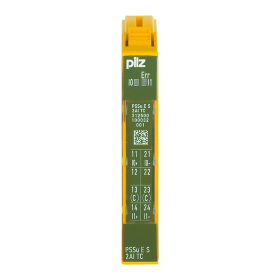
Page 8: Front View
Serial number – Hardware version number – 2D code 3: Labelling strip for the terminal configuration on the base module 4: Name of electronic module 5: Connection level 1 6: Connection level 2 Operating Manual PSSu E S 2AI TC(-T) 22029-EN-06... - Page 9 10: Round connection holes (connection levels 1, 2, 3 and 4) for connecting the signal lines 11: Mounting slot for colour marker to label the connection level (connection levels 1, 2, 3 and 4) Operating Manual PSSu E S 2AI TC(-T) 22029-EN-06...
-
Page 10: Safety
The module provides analogue inputs. It may be used as an input module for standard functions. The modules PSSu E S 2AI TC and PSSu E S 2AI TC-T may be used as a safety compon- ent in accordance with the Lifts Directive 95/16/EC, EN 81-1, EN 81-2 and EN 115-1. -
Page 11: Safety Regulations
In safety-related applications, please comply with the mission time T in the safety-re- lated characteristic data. When decommissioning, please comply with local regulations regarding the disposal of electronic devices (e.g. Electrical and Electronic Equipment Act). Operating Manual PSSu E S 2AI TC(-T) 22029-EN-06... -
Page 12: Function Description
This way the configuration data is retained even if you change the input module. Schematic representation of signal processing: Lineari- Input Filter sation Manufact. User scaling scaling Reference Range Data module monitoring temp. format Operating Manual PSSu E S 2AI TC(-T) 22029-EN-06... -
Page 13: Integrated Protection Mechanisms
The module can be configured for voltage measurement: -30 ... 30 mV -60 ... 60 mV -120 ... 120 mV The temperature ranges for these measuring ranges can be found in the technical details. Operating Manual PSSu E S 2AI TC(-T) 22029-EN-06... -
Page 14: Open Circuit Detection
The reference temperature is measured in the base module. For each input, the reference temperature at the connection points is measured using a temperature-dependent resistor (PT1000). The Pt1000 sensors are located in the base module between terminals 21 and 12 / 24 and 12. Operating Manual PSSu E S 2AI TC(-T) 22029-EN-06... -
Page 15: Digital Filter
50 Hz 80 dB 122 ms 244 ms 50 Hz and 60 Hz 65 dB 122 ms 244 ms 50 Hz and 60 Hz 69 dB 202 ms 404 ms 50 Hz and 60 Hz 74 dB 482 ms 964 ms Operating Manual PSSu E S 2AI TC(-T) 22029-EN-06... -
Page 16: Scaling
Scaling is a multi-stage process to adapt the values from the AD converter. The straight path in the diagram indicates the default configuration. raw value Hardware calibration Manuf. scaling active? Manufacturer scaling User scaling active? User scaling Output formats Operating Manual PSSu E S 2AI TC(-T) 22029-EN-06... -
Page 17: Values That Fall Outside The Range Limits
The following examples show the relationship between the values with default scaling. You can configure the following data formats: Two's complement (default) The digital values are transferred with 16 bits. Operating Manual PSSu E S 2AI TC(-T) 22029-EN-06... -
Page 18: Summary And Overview
Type "R", Type "S", Type "B", Type "J", Type Type "K" "T", Type "E", Type "K", Type "N", ±30 mV, ±60 mV, ±120 mV Open circuit detec- Activated/TRUE tion Range monitoring Activated/TRUE Reference temperat- Activated/TRUE ure measurement Operating Manual PSSu E S 2AI TC(-T) 22029-EN-06... -
Page 19: Pssu Assignment In System Environment A
All the status bytes are displayed first in the PII, followed by the input data. Configuration Standard bus system ST-PII ST-PIO Input data 32 Bit - - - Input data and status byte ("X") 48 Bit - - - Operating Manual PSSu E S 2AI TC(-T) 22029-EN-06... -
Page 20: Status Byte
Input value above or equal to the lower limit value Value below the lower limit value Input value below or equal to the upper limit value Value exceeds the upper limit value 2-5, 7 Reserved Reserved No module error Module error Operating Manual PSSu E S 2AI TC(-T) 22029-EN-06... -
Page 21: Pssu Assignment In System Environment B
0: Input value above or equal to the lower limit value 1: Value below the lower limit value Overrange: BOOL 0: Input value below or equal to the upper limit value 1: Value exceeds the upper limit value Operating Manual PSSu E S 2AI TC(-T) 22029-EN-06... -
Page 22: Installation
5.1.1 Dimensions Base modules with four connection levels: 12,6 mm 8,1 mm 52,1 mm (0.496") (0.319") (2.051") 12,6 mm 72,6 mm (0.496") (2.858") Operating Manual PSSu E S 2AI TC(-T) 22029-EN-06... -
Page 23: Installing The Base Module
Push the base module back [2] until you hear it lock into position. On the mounting rail, slide the base module to the left until you hear the two lateral mounting hooks on the adjacent module lock into position [3]. Schematic representation: Operating Manual PSSu E S 2AI TC(-T) 22029-EN-06... -
Page 24: Inserting And Removing An Electronic Module
This is how the base module is coded. The mechanics of the electronic modules are designed for 50 plug in/out cycles. Operating Manual PSSu E S 2AI TC(-T) 22029-EN-06... -
Page 25: Inserting An Electronic Module
Installation 5.3.1 Inserting an electronic module Procedure: The electronic module must audibly lock into position [1]. Mark the electronic module using the labelling strips [2]. Schematic representation: Operating Manual PSSu E S 2AI TC(-T) 22029-EN-06... -
Page 26: Removing An Electronic Module
The substitute values are used for the modules' FS outputs, with Valid Bits = FALSE. CAUTION! Sparking can cause interference and errors! Only change the module when the load is switched off! Operating Manual PSSu E S 2AI TC(-T) 22029-EN-06... -
Page 27: Wiring
Strip the wire back 8 mm. If necessary, label the connection level with a colour marker [3]. Base module with screw terminals: – Use a screwdriver to loosen the screw on the screw terminal [1] Operating Manual PSSu E S 2AI TC(-T) 22029-EN-06... - Page 28 Digital inputs: 1.5 mm (AWG16) – Digital outputs: 2.0 mm (AWG14) – Inputs/outputs on the counter modules: 1.5 mm (AWG16) – Analogue inputs/outputs: 1.5 mm (AWG16) – Communication cables: 1.5 mm (AWG16) – Test pulse outputs: 1.5 mm (AWG16) Operating Manual PSSu E S 2AI TC(-T) 22029-EN-06...
-
Page 29: Terminal Configuration
Cage clamp terminals: PSSu BP 1/8 C-J 21: Input I0- PSSu BP 1/8 C-TJ 12-22: n. n. 13-23: Shield connection (13-23 linked within the base module) 14: Input I1+ 24: Input I1- Operating Manual PSSu E S 2AI TC(-T) 22029-EN-06... -
Page 30: Connecting The Module
PSSu BP-C 1/8 C-TJ 12-22: n. n. 13-23: C-rail supply, shield connection (13-23 linked within the base module) 14: Input I1+ 24: Input I1- Connecting the module Input circuit Without C-rail With C-rail Thermocouple Operating Manual PSSu E S 2AI TC(-T) 22029-EN-06... -
Page 31: Operation
LED on LED off 7.2.1 Display elements for module diagnostics The module has an LED for displaying module errors ("Err" LED). Meaning Designation Colour Status - - - No error Module is faulty Operating Manual PSSu E S 2AI TC(-T) 22029-EN-06... -
Page 32: Display Elements For Input Status
- - - No sig- 11, 21 nal de- (Input 1) tected Green Signal detected - - - No sig- 14, 24 nal de- (Input 2) tected Green Signal detected Operating Manual PSSu E S 2AI TC(-T) 22029-EN-06... -
Page 33: Technical Details
Type K, Type N, Type R, Type S, Type K, Type N, Type R, Type S, Type T Type T Input area Thermocouples in accordance with the standard EN 60584-1 EN 60584-1 Operating Manual PSSu E S 2AI TC(-T) 22029-EN-06... - Page 34 4 µV (+/-120 mV) 100 MOhm 100 MOhm Input resistance Max. continuous voltage Temperature measurement Value of least significant bit (LSB) 0,0625 K 0,0625 K Typ. conversion time per input 404 ms 404 ms Operating Manual PSSu E S 2AI TC(-T) 22029-EN-06...
- Page 35 61000-4-4, EN 61000-4-5, EN 61000-4-4, EN 61000-4-5, EN 61000-4-6, EN 61131-2 61000-4-6, EN 61131-2 Vibration In accordance with the standard EN 60068-2-6 EN 60068-2-6 10,0 - 150,0 Hz 10,0 - 1000,0 Hz Frequency Acceleration Operating Manual PSSu E S 2AI TC(-T) 22029-EN-06...
- Page 36 12,6 mm 12,6 mm Depth 60,2 mm 60,2 mm 36 g 36 g Weight Mechanical coding Type Colour Dark grey Dark grey Where standards are undated, the 2009-03 latest editions shall apply. Operating Manual PSSu E S 2AI TC(-T) 22029-EN-06...
-
Page 37: Order Reference
Base module with C-rail and cage clamp terminals, with integ- 312 613 rated cold junction compensation PSSu BP-C 1/8 C-TJ Base module with C-rail and cage clamp terminals, with integ- 314 613 rated cold junction compensation, T-type Operating Manual PSSu E S 2AI TC(-T) 22029-EN-06... - Page 38 Front cover Support Technical support is available from Pilz round the clock. Americas Australia Scandinavia Brazil +61 3 95446300 +45 74436332 +55 11 97569-2804 Spain Canada Europe +34 938497433 +1 888-315-PILZ (315-7459) Austria Switzerland +41 62 88979-30 Mexico +43 1 7986263-0...