
Summary of Contents for Fluke OptiFiber Smart Remote
- Page 1 OFSR-X OptiFiber Smart Remote Options Users Manual PN 2140377 May 2004 © 2004 Fluke Corporation. All rights reserved. Printed in USA. All product names are trademarks of their respective companies.
- Page 2 LIMITED WARRANTY AND LIMITATION OF LIABILITY Each Fluke Networks product is warranted to be free from defects in material and workmanship under normal use and service. The warranty period is one year and begins on the date of purchase. Parts, accessories, product repairs and services are warranted for 90 days. This war-...
-
Page 3: Table Of Contents
Table of Contents Title Page Overview of Features ....................1 Registration ........................1 Contacting Fluke Networks ..................2 Additional Resources for Cable Testing Information ..........2 Unpacking........................3 OFSR-MMREM Smart Remote with Multimode Module ........3 OFSR-SFM Singlemode Module................3 OFSR-MFM Multimode Module ................ - Page 4 OFSR-X OptiFiber Smart Remote Options Users Manual Options and Accessories ....................19 Maintenance ......................... 20 Cleaning........................20 Factory Calibration....................20 Resetting the Battery Gauge ................... 21 Replacing the Battery ....................21 Updating the Smart Remote’s Software ..............22 Specifications ........................ 24 Environmental and Regulatory Specifications............
- Page 5 List of Figures Figure Title Page Smart Remote Features ....................... 8 Fiber Module Features ......................10 Battery Charging, Removal, and Status................13 Using an OFSR-X in Smart Remote Mode................14 Equipment for Using the Visual Fault Locator..............15 Using the Visual Fault Locator .................... 17 Using the Smart Remote as an Optical Source..............
- Page 6 OFSR-X OptiFiber Smart Remote Options Users Manual...
-
Page 7: Overview Of Features
The OFSR-X OptiFiber Smart Remote options are used Registering your product with Fluke Networks gives you with the OptiFiber Certifying OTDR to measure loss and access to valuable information on product updates, length on fiber optic cabling. The smart remote offers troubleshooting tips, and other support services. -
Page 8: Contacting Fluke Networks
Additional Resources for Cable Testing Information Note The Fluke Networks Knowledge Base answers common If you contact Fluke Networks about your smart questions about Fluke Networks products and provides remote, have the smart remote's software and articles on cable testing techniques and technology. -
Page 9: Unpacking
Unpacking OFSR-SFM Singlemode Module Unpacking • One DTX-SFM singlemode fiber module Three OFSR-X options with their accessories are listed • Two 9/125 µm singlemode patch cords, 2 m, SC/SC below. If something is damaged or missing, contact the place of purchase immediately. •... -
Page 10: Safety Information
OFSR-X OptiFiber Smart Remote Options Users Manual Safety Information Table 1 shows the international electrical symbols used on the smart remote or in this manual. Table 1. International Electrical Symbols Warning: Risk of fire, electric shock, or personal injury. Warning or Caution: Risk of damage or destruction to equipment or software. - Page 11 • Do not modify the smart remote. permanently damage your eyes. • Use only ac adapters approved by Fluke • Keep the fiber module’s OUTPUT port covered Networks for use with the smart remote to with a dust plug or keep a patch cord attached.
- Page 12 OFSR-X OptiFiber Smart Remote Options Users Manual • Caution Never look directly into the visual fault locator output. Momentary exposure to the locator’s To avoid damaging the smart remote or cables output will not damage your eyes; however, under test, to avoid data loss, and to ensure...
- Page 13 Safety Information • Use a Fluke Networks FiberInspector Video Microscope to periodically inspect the fiber module’s OUTPUT connector for scratches and other damage. • Do not use a video microscope to inspect the fiber module’s INPUT connector. This connector has different dimensions than the OUTPUT connector, and may be damaged by a fiber inspection probe.
-
Page 14: Getting Acquainted
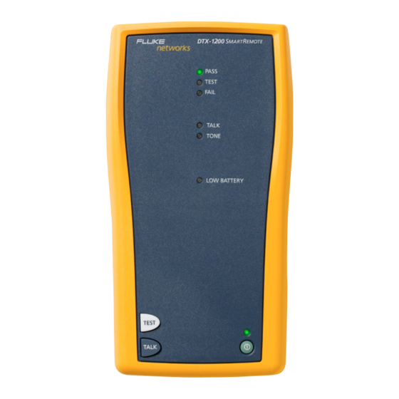
OFSR-X OptiFiber Smart Remote Options Users Manual Physical Features Getting Acquainted Figure 1 describes the smart remote’s features and shows The following sections introduce the smart remote's basic how to remove and install the fiber module. Figure 2 features. describes the fiber module’s features. - Page 15 Getting Acquainted : Not used with an OptiFiber tester. If you Note unintentionally press , hold down for one The LEDs also act as a battery gauge. See second to exit talk mode Figure 3 on page 13. : On/off key. Pass LED lights when a test passes.
- Page 16 OFSR-X OptiFiber Smart Remote Options Users Manual awl03f.eps Figure 2. Fiber Module Features...
- Page 17 Getting Acquainted Button for activating the visual fault locator (B) and SC output connector with dust cap. Transmits optical signals for loss and length measurements. output port (D). See “Using the Visual Fault Locator” on page 15 and “Using the Smart Remote as an Optical The LED below the connector is red when the output is Source”...
-
Page 18: Powering The Smart Remote
OFSR-X OptiFiber Smart Remote Options Users Manual Powering the Smart Remote The LED near the ac adapter connection indicates the following: To charge the battery, connect the ac adapter provided, • as shown in Figure 3. You may charge the battery when it Red: battery is charging. - Page 19 Getting Acquainted Charging the battery 91 % - 100 % PASS PASS TEST FAIL 75 % - 90 % TEST TALK TONE 59 % - 74 % FAIL LOW BATTERY 42 % - 58 % TALK 25 % - 41 % TONE TEST TALK...
-
Page 20: Using The Smart Remote With Optifiber
OFSR-X OptiFiber Smart Remote Options Users Manual Using the Smart Remote with OptiFiber Use the smart remote in place of a second OptiFiber tester for loss/length testing in Smart Remote mode. Figure 4 shows examples of reference and test connections. See... -
Page 21: Using The Visual Fault Locator
Using the Visual Fault Locator Using the Visual Fault Locator PASS The smart remote includes a visual fault locator that helps TEST FAIL you quickly check fiber continuity, trace fibers, and locate TALK TONE faults along fibers and in connectors. LOW BATTERY The visual fault locator port accepts connectors with 2.5 mm ferrules (SC, ST, or FC). - Page 22 OFSR-X OptiFiber Smart Remote Options Users Manual Using the Visual Fault Locator Clean the connectors on the patch cord, if used, and To check continuity or trace fiber connections, look for the fiber to be tested. the red light at the end of the fiber.
- Page 23 Using the Visual Fault Locator Continuity check/tracing fibers • Press once: ON • Press again: Blinking • Press again: OFF Microbend or broken fiber Broken fiber connector in connector Bad splice Sharp bend awl06f.eps Figure 6. Using the Visual Fault Locator...
-
Page 24: Using The Smart Remote As A Manually-Controlled Optical Source
OFSR-X OptiFiber Smart Remote Options Users Manual Using the Smart Remote as a To turn on the source, use the button on the fiber module as described in Figure 7. Manually-Controlled Optical Source You can manually-control the smart remote as a source for loss and power measurements with an OptiFiber tester or any optical power meter. -
Page 25: Options And Accessories
Options and Accessories To order options or accessories, contact Fluke Networks Options and Accessories as described on page 2. Table 2 shows options and accessories available for the OFSR-X smart remote. For a complete list of options and accessories visit the Fluke Networks website at www.flukenetworks.com. -
Page 26: Maintenance
• Use only specified replacement parts for user- or exceed the published accuracy specifications. Contact replaceable items. an authorized Fluke Networks Service Center for information on getting your smart remote calibrated. • Use only Fluke Networks authorized service centers. -
Page 27: Resetting The Battery Gauge
Maintenance Resetting the Battery Gauge Replacing the Battery The accuracy of the battery gauge may drift over time if Replace the lithium ion battery pack when its life the battery is frequently recharged before being fully becomes noticeably shorter or when it fails to reach full charge. -
Page 28: Updating The Smart Remote's Software
Make the connections shown in Figure 8. Turn on the smart remote. Download the smart remote update file from the Fluke Networks website, or contact Fluke Networks Select Utilities > DTX Utilities > Software Version to get the update by other means. You can access from the LinkWare menu. - Page 29 Maintenance Select Utilities > DTX Utilities > Software Update from the LinkWare menu, locate and select the update file; then click Open. To verify the update, select Utilities > DTX Utilities > Software Version from the LinkWare menu. USB cable PASS TEST FAIL...
-
Page 30: Specifications
OFSR-X OptiFiber Smart Remote Options Users Manual Specifications Environmental and Regulatory Specifications Operating temperature 32 °F to 113 °F (0 C to 45 Storage temperature -4 °F to +140 °F (-20 C to +60 Operating relative humidity 95 % (50 °F to 95 °F; 10... -
Page 31: Optical Specifications (23 C)
Specifications Optical Specifications (23 Input/output (meter/source) connectors SC/SC Source type and nominal wavelength DTX-MFM : 850 nm LED and 1300 nm LED DTX-SFM: 1310 nm FP LD and 1550 nm FP LD DTX-MFM: 850 ± 30 nm, 1300 ± 20 nm Source wavelengths DTX-SFM: 1310 ±... - Page 32 OFSR-X OptiFiber Smart Remote Options Users Manual Optical Specifications (cont.) Power meter type InGaAs detector Power meter calibrated wavelengths 850 nm, 1310 nm, 1550 nm Power measurement range 0 dBm to -60 dBm (1310 nm and 1550 nm) 0 dBm to -52 dBm (850 nm) ±...
-
Page 33: Visual Fault Locator Specifications (23 C)
Specifications Visual Fault Locator Specifications (23 316 µw (-5 dBm) ≤ peak power ≥ 1.0 mw (0 dbm) Output power* Operating wavelength 650 nm nominal ± 3 nm Spectral width (RMS) Output modes Continuous wave and pulsed mode (2 Hz to 3 Hz blink frequency) Connector adapter 2.5 mm universal Laser safety... -
Page 34: Communications Port
OFSR-X OptiFiber Smart Remote Options Users Manual Communications Port USB, mini B connector Re-calibration period 1 year Dimensions and Weight • 8.5 in x 4.5 in x 2.3 in (21.6 cm x 11.4 cm x 5.8 cm), nominal • 2.3 lb (1.05 kg), nominal, with module installed...