
Related Manuals for Texas Instruments TRF7960TB


Summary of Contents for Texas Instruments TRF7960TB
- Page 1 TRF7960TB HF RFID Reader Module User's Guide Literature Number: SLOU297 October 2010...
- Page 2 SLOU297 – October 2010 Submit Documentation Feedback Copyright © 2010, Texas Instruments Incorporated...
-
Page 3: Table Of Contents
DK-LM3S9B96-EM2-TRF7960R ARM® Cortex™-M3 Development Board ........................Quick Start ....................Base Application Firmware ....................Platform Specific Details ..................Mechanical/Physical Information ...................... Antenna Tuning Details ..................TRF7960TB Module Read Ranges SLOU297 – October 2010 Table of Contents Submit Documentation Feedback Copyright © 2010, Texas Instruments Incorporated... - Page 4 ................... TRF7960TB Module Schematic ................MSP-EXP430F5438 Development Board Debug Header (RF3) Logic Analyzer Connections for Monitoring SPI Communications Between ............. MSP430F5438A and TRF796x on TRF7960TB Module ......Firmware Development\Debug Setup for MSP-EXP430F5438 Experimenters Board ............. DK-LM3S9B96-EM2-TRF7960R Development Platform ..................Mechanical/Physical Information ................
-
Page 5: Purpose
EM socket headers populated. Scope This document describes the TRF7960TB module as it relates to using the module for evaluation and development purposes in conjunction with Texas Instruments Embedded Development platforms. This manual does not cover the in-depth details of the TRF796x reader IC family, as those details are... -
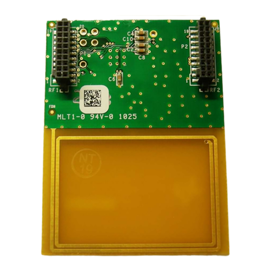
Page 6: Trf7960Tb Module Description
1) allows the software application developer to become familiar with the functionalities of TRF7960 Multi-Standard Fully Integrated 13.56-MHz RFID reader IC with the freedom to develop on the Texas Instruments embedded microcontroller development platform of choice. The TRF7960TB module also allows customer-driven antenna tuning with onboard coil and customer-driven antenna form factor design. -
Page 7: Trf7960Tb Connections/Technical Details
No connection MOSI I/O 7, master out/slave in (data in from microcontroller) Ground MISO I/O 6, master in/slave out (data out from TRF7960) SLOU297 – October 2010 TRF7960TB HF RFID Reader Module Submit Documentation Feedback Copyright © 2010, Texas Instruments Incorporated... -
Page 8: Connector P2/Rf2
Direct mode, selection between ASK and OOK modulation (0 = ASK, 1 = OOK) ASK/OOK Also can be configured to provide the received analog signal output (ANA_OUT). No connection No connection TRF7960TB HF RFID Reader Module SLOU297 – October 2010 Submit Documentation Feedback Copyright © 2010, Texas Instruments Incorporated... -
Page 9: Trf7960Tb Module Schematic
TRF7960TB Module Schematic www.ti.com TRF7960TB Module Schematic Figure 2 shows a schematic of the TRF7960TB module. Figure 2. TRF7960TB Module Schematic SLOU297 – October 2010 TRF7960TB HF RFID Reader Module Submit Documentation Feedback Copyright © 2010, Texas Instruments Incorporated... -
Page 10: Msp-Exp430F5438 Experimenters Board
The TRF7960TB module plugs into the RF1 and RF2 headers on this MSP-EXP board (see Figure 3). For logic analyzer connection during firmware debug, user can use test points on TRF7960TB board or pins on header RF3. RF3 Debug Header... -
Page 11: Debug Header (Rf3) Logic Analyzer Connections For Monitoring Spi Communications Between Msp430F5438A And Trf796X On Trf7960Tb Module
MSP-EXP430F5438 Experimenters Board www.ti.com Figure 4. Debug Header (RF3) Logic Analyzer Connections for Monitoring SPI Communications Between MSP430F5438A and TRF796x on TRF7960TB Module RF3 Debug Header Figure 5. Firmware Development\Debug Setup for MSP-EXP430F5438 Experimenters Board SLOU297 – October 2010 TRF7960TB HF RFID Reader Module Submit Documentation Feedback Copyright ©... -
Page 12: Lm3S9B96-Em2-Trf7960R Arm® Cortex™-M3 Development Board
Graphics Library in conjunction with ARM development tools from ARM tools partners. An EPI header to EM header interface board (DK-LM3S9B96-EM2) is needed for use with the TRF7960TB module. Figure 6. DK-LM3S9B96-EM2-TRF7960R Development Platform TRF7960TB HF RFID Reader Module SLOU297 –... -
Page 13: Quick Start
Quick Start www.ti.com Quick Start 1. Plug the TRF7960TB module into the microcontroller development platform of choice. NOTE: If using the DK-LM3S9B96 board, remove the SDRAM module and replace it with the DK-LM3S9B96-EM2 interface board before mounting the TRF7960TB module. -
Page 14: Mechanical/Physical Information
Mechanical/Physical Information www.ti.com Mechanical/Physical Information Figure 7. Mechanical/Physical Information TRF7960TB HF RFID Reader Module SLOU297 – October 2010 Submit Documentation Feedback Copyright © 2010, Texas Instruments Incorporated... -
Page 15: Antenna Tuning Details
Q factor or experimenting further to improve a particular application. TRF7960TB coil antenna tuning details starts with calculations to produce the theoretical values shown below (and based on measurements of antenna coil on Rev B board.) Coil value nominally measures 0.95 µH at 13.56 MHz and XL = 0.8 + j80.8 = 0.990 at 63.4°. -
Page 16: Smith Chart Simulation
82 pF and 69 pF, respectively. This is less than a +4% change from the calculated value. Figure 9. Smith Chart Simulation (R = 680 Ω) TRF7960TB HF RFID Reader Module SLOU297 – October 2010 Submit Documentation Feedback Copyright © 2010, Texas Instruments Incorporated... -
Page 17: Theoretical Parallel Resistor Value For Desired Q
102E-12 92E-12 82E-12 82E-12 72E-12 68E-12 62E-12 51E-12 52E-12 42E-12 Q Value Figure 11. Theoretical Capacitance Values for Resonance at Desired Q SLOU297 – October 2010 TRF7960TB HF RFID Reader Module Submit Documentation Feedback Copyright © 2010, Texas Instruments Incorporated... -
Page 18: Higher Q Antenna Measurement Plots With Calculated Values (Q = ~20)
Figure 12 Figure 13 show actual measurements on TRF7960TB module for high and lower Q value tuning solutions. Figure 12. Higher Q Antenna Measurement Plots with Calculated Values (Q = ~20) Figure 13. Lower Q Antenna Measurement Plots with Calculated Values (Q = ~10) TRF7960TB HF RFID Reader Module SLOU297 –... -
Page 19: Trf7960Tb Module Read Ranges
TRF7960TB Module Read Ranges www.ti.com TRF7960TB Module Read Ranges Figure 14 through Figure 16 show read ranges for the TRF7960TB using different ISO standards. RI-I16-11xA-xx RI-HDT-DVBx RI-I17-11xA-xx RI-I03-11xA-xx RI-I11-11xA/B-xx RI-I15-112B-03 RI-I02-11xA/B-xx (24.2mm) (22mm) (32.5mm) (38mm x 22.5mm) (45mm x 45mm) - Page 20 IMPORTANT NOTICE Texas Instruments Incorporated and its subsidiaries (TI) reserve the right to make corrections, modifications, enhancements, improvements, and other changes to its products and services at any time and to discontinue any product or service without notice. Customers should obtain the latest relevant information before placing orders and should verify that such information is current and complete.
- Page 21 Mouser Electronics Authorized Distributor Click to View Pricing, Inventory, Delivery & Lifecycle Information: Texas Instruments TRF7960ATB...