Advertisement
Available languages
Available languages
Quick Links
Owner's Manual
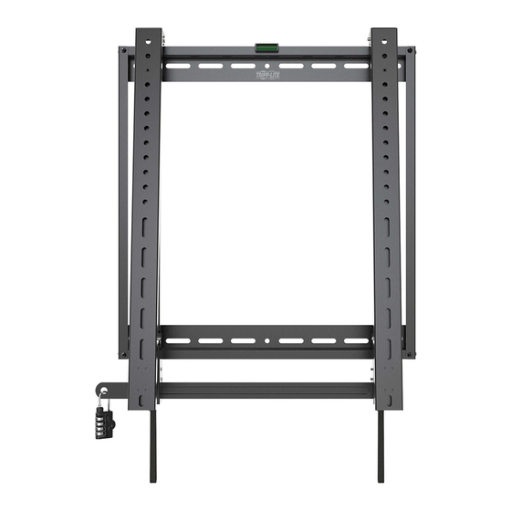
Portrait Flat-Panel
Fixed Wall Mount
CAUTION: DO NOT EXCEED MAXIMUM LISTED WEIGHT CAPACITY. SERIOUS INJURY OR
PROPERTY DAMAGE MAY OCCUR!
200 x 200 / 300 x 300
200 x 400 / 400 x 400
400 x 600
Español 14 • Français 27 • Русский 40 • Deutsch 53
Register your product for quicker service and ultimate peace of mind.
You could also win an ISOBAR6ULTRA surge protector—a $100 value!
1111 W. 35th Street, Chicago, IL 60609 USA • www.tripplite.com/support
18-11-270-9338F2.indb 1
(with Security)
Model: DWFPSC4570M
70"
MAX
PROTECT YOUR INVESTMENT!
www.tripplite.com/warranty
Copyright © 2019 Tripp Lite. All rights reserved.
1
110 lb.
(50 kg)
MAX
1/4/2019 10:47:06 AM
Advertisement

Related Manuals for Tripp Lite DWFPSC4570M


Summary of Contents for Tripp Lite DWFPSC4570M
- Page 1 Register your product for quicker service and ultimate peace of mind. You could also win an ISOBAR6ULTRA surge protector—a $100 value! www.tripplite.com/warranty 1111 W. 35th Street, Chicago, IL 60609 USA • www.tripplite.com/support Copyright © 2019 Tripp Lite. All rights reserved. 18-11-270-9338F2.indb 1 1/4/2019 10:47:06 AM...
- Page 2 PRODUCT REGISTRATION Visit www.tripplite.com/warranty today to register your new Tripp Lite product. You’ll be automatically entered into a drawing for a chance to win a FREE Tripp Lite product!* * No purchase necessary.
- Page 3 Component Checklist IMPORTANT: Ensure all parts according to the component checklist have been received prior to installation. If any parts are missing or faulty, visit www.tripplite.com/support for service. Vertical Wall Plate (x2) Horizontal Wall Plate (x2) Security Bar (x1) Adapter Bracket (x2) M5 x 8 Screw (x8) Bubble Level (x1) Combo Lock (x1)
- Page 4 1. Assemble the Wall Plate M5 x 8 Vertical Wall Plate Horizontal Wall Plate M5 x 8 Attach the vertical wall plates to the horizontal wall plates using the appropriate screws. Tighten all screws with a proper screwdriver. Bubble Level 18-11-270-9338F2.indb 4 1/4/2019 10:47:07 AM...
- Page 5 2a. Mount on Wood Stud Wall 55 mm (2.2 in.) O4.5 mm O(3/16 in.) Find and mark the exact location of mounting holes Drill pilot holes Washer Anchor Bolt Screw the WARNING assembled wall plate • Make sure that mounting screws are anchored into the center of the onto the wall studs.
- Page 6 2b. Mount on Solid Brick and Concrete Block 60 mm (2.4 in.) O10 mm O(3/8 in.) Find and mark the Drill pilot holes exact location of mounting holes Concrete Anchor D6 Washer Anchor Bolt Screw the assembled wall plate onto the wall WARNING •...
- Page 7 3. Install Adapter Brackets Adapter Bracket Protective Strips Remove the screws on the protective strips. Remove the protective strips. 3a. For Flat Back Screen M5 x 14 M6 x 14 M8 x 20 Washer Note: Choose appropriate screws, washers and spacers (if necessary) according to the type of screen.
- Page 8 3. Install Adapter Brackets 3b. For Protruded or Recessed Back Screen M8 x 20 M6 x 30 M6 x 30 M6 x 30 M8 x 20 M8 x 30 M8 x 30 M8 x 30 Washer Washer Washer Washer Small Small Spacer Small...
- Page 9 3. Install Adapter Brackets 3b. For Protruded or Recessed Back Screen (continued) Protective Strips Reattach the protective strips to the adapter brackets using the previously removed screws. 18-11-270-9338F2.indb 9 1/4/2019 10:47:12 AM...
- Page 10 4. Hang Display onto the Wall Plate Wall Wall Using an assistant or mechanical lifting equipment, hook the display with attached adapter brackets over the top of the mounted wall plate. Wall Wall Open the kickstands to Make sure the bracket is hold the display.
- Page 11 5. Slide Security Bar through the Mounting Brackets and Attach Combo Lock to Secure Security Insert the security bar to the secure the rail. Security Combo Lock 18-11-270-9338F2.indb 11 1/4/2019 10:47:13 AM...
- Page 12 5. Slide Security Bar through the Mounting Brackets and Attach Combo Lock to Secure Wall Wall Security Security Fold the kickstands after finishing the security bar installation. 18-11-270-9338F2.indb 12 1/4/2019 10:47:14 AM...
- Page 13 6. Removing the Display Wall Security Bar Remove the security bar. Pull the two straps down to unlock the adapter brackets from the wall plate assembly. Wall Wall Wall Using an assistant or mechanical lifting equipment, carefully lift the display and remove the display from the wall plate.
- Page 14 400 x 600 MÁXIMO English 1 • Français 27 • Русский 40 • Deutsch 53 1111 W. 35th Street, Chicago, IL 60609 EE UU • www.tripplite.com/support Copyright © 2019 Tripp Lite. Todos los derechos reservados. 18-11-270-9338F2.indb 14 1/4/2019 10:47:15 AM...
- Page 15 NOTA: Lea completo todo el manual de instrucciones antes de iniciar la instalación y ensamble. ADVERTENCIA • No inicie la instalación hasta que haya leído y entendido las instrucciones y advertencias contenidas en este manual. Si tiene cualquier pregunta con respecto a cualquiera de las instrucciones o advertencias, visite www.tripplite.com/support.
- Page 16 Accesorios y Partes Incluidas en el Empaque IMPORTANTE: Antes de instalar, cerciórese de haber recibido todas las partes de acuerdo a la lista de comprobación de componentes. Si faltase cualquier parte o estuviese dañada, visite www.tripplite.com/support para solicitar servicio. Placa de Pared Vertical Placa de Pared Horizontal (x2) (x2)
- Page 17 1. Ensamble la Placa de Pared M5 x 8 Placa de Pared Vertical Placa de Pared Horizontal M5 x 8 Instale las placas verticales de pared a las placas horizontales de pared usando los tornillos adecuados. Apriete todos los tornillos con un desatornillador adecuado. Nivel de Burbuja 18-11-270-9338F2.indb 17...
- Page 18 2a. Instalación en Pared con Entramado de Madera 55 mm [2.2"] Ø 4.5 mm Ø [3/16"] Encuentre y marque la posición exacta de los orificios de instalación Barrene los orificios piloto Arandela Tornillo de Anclaje Atornille ADVERTENCIA la placa de pared •...
- Page 19 2b. Instalación sobre Ladrillos Sólidos o Bloques de Concreto 60 mm [2.4"] Ø 10 mm Ø [3/8"] Encuentre Barrene los y marque la orificios piloto posición exacta de los orificios de instalación Taquete Arandela D6 Tornillo de Anclaje Atornille la placa de pared ensamblada a la pared...
- Page 20 3. Instale los Soportes del Adaptador Soporte Adaptador Barras de Protección Quite los tornillos de las barras de protección. Retire las barras de protección. 3a. Para Pantalla con la Parte Posterior Plana M5 x 14 M6 x 14 M8 x 20 Arandela Nota: Elija los tornillos, arandelas y espaciadores (si fueran necesarios) apropiados de acuerdo al tipo de...
- Page 21 3. Instale los Soportes del Adaptador 3b. Para Pantalla con Parte Posterior Cóncava o Convexa M6 x 30 M6 x 30 M6 x 30 M8 x 20 M8 x 20 M8 x 30 M8 x 30 M8 x 30 Arandela Arandela Arandela Arandela...
- Page 22 3. Instale los Soportes del Adaptador 3b. Para Pantalla con Parte Posterior Cóncava o Convexa (continuación) Barras de Protección Vuelva a colocar las barras de protección a los soportes del adaptador usando los tornillos retirados anteriormente. 18-11-270-9338F2.indb 22 1/4/2019 10:47:19 AM...
- Page 23 4. Cuelgue la Pantalla en la Placa de Pared Pared Pared Usando un ayudante o equipo de elevación mecánico, cuelgue la pantalla con los soportes del adaptador colocados sobre la Pared Pared parte superior de la placa de pared instalada. Abra las patas de apoyo Asegúrese de que el soporte esté...
- Page 24 5. Deslice la Barra de Seguridad a Través de los Soportes de Instalación e Instale el Candado de Combinación para Asegurarla Barra de Seguridad Inserte la barra de seguridad para fijar el riel. Barra de Seguridad Candado de Combinación 18-11-270-9338F2.indb 24 1/4/2019 10:47:21 AM...
- Page 25 5. Deslice la Barra de Seguridad a Través de los Soportes de Instalación e Instale el Candado de Combinación para Asegurarla Pared Pared Barra de Seguridad Barra de Seguridad Pliegue las patas de apoyo después de terminar la instalación de la barra de seguridad. 18-11-270-9338F2.indb 25 1/4/2019 10:47:21 AM...
- Page 26 6. Desinstalación de la Pantalla Pared Barra de Seguridad Retire la barra de seguridad. Jale hacia abajo las dos correas para desbloquear los soportes del adaptador del conjunto de la placa de pared. Pared Pared Pared Usando un ayudante o equipo de elevación mecánico, levante la pantalla y retire con cuidado la pantalla de la placa de pared.
- Page 27 (110 lb) 400 x 600 MAX. English 1 • Español 14 • Русский 40 • Deutsch 53 1111 W. 35th Street, Chicago, IL 60609 USA • www.tripplite.com/support Droits d'auteur © 2019 Tripp Lite. Tous droits réservés. 18-11-270-9338F2.indb 27 1/4/2019 10:47:22 AM...
- Page 28 REMARQUE : Lire le manuel d'instructions dans son intégralité avant de commencer l'installation et l'assemblage. AVERTISSEMENT • Ne pas commencer l'installation avant d'avoir lu et compris les instructions et les avertissements contenus dans le présent manuel. Pour toute question concernant les instructions ou les avertissements, veuillez visiter www.tripplite.com/support.
- Page 29 Liste de vérification des composants IMPORTANT : S'assurer d'avoir reçu toutes les pièces conformément à la liste de vérification des composants avant de procéder à l'installation. Si des pièces sont manquantes ou défectueuses, visiter www.tripplite.com/support pour obtenir de l'aide. Plaque murale verticale Plaque murale horizontale (x2) (x2)
- Page 30 1. Assemblage de la plaque murale M5 x 8 Plaque murale verticale Plaque murale horizontale M5 x 8 Fixer les plaques murales verticales aux plaques murales horizontales en utilisant les vis appropriées. Serrer toutes les vis avec un tournevis approprié. Niveau à...
- Page 31 2a. Montage sur des montants muraux 55 mm (2,2 po) O 4,5 mm O (3/16 po) Déterminer et marquer l'emplacement exact des trous de montage. Percer des avant-trous. Rondelle Boulon d'ancrage Visser la AVERTISSEMENT plaque murale au • S'assurer que les vis de montage sont ancrées au centre des montants. mur.
- Page 32 2b. Montage sur de la brique solide ou des blocs en béton 60 mm (2,4 po) O 10 mm O (3/8 po) Déterminer Percer des et marquer avant-trous. l'emplacement exact des trous de montage. Ancrage à béton Rondelle D6 Boulon d'ancrage Visser la plaque murale au mur.
- Page 33 3. Installer les supports d'adaptateur. Support Bandes de d'adaptateur protection Retirer les vis sur les bandes de protection. Retirer les bandes de protection. 3a. Pour les écrans à dos plat M5 x 14 M6 x 14 M8 x 20 Rondelle Remarque : Choisir les vis, les rondelles et les en- tretoises appropriées (le cas échéant) en fonction du type d'écran.
- Page 34 3. Installer les supports d'adaptateur. 3b. Pour les écrans en saillie ou à dos encastré M8 x 20 M6 x 30 M6 x 30 M6 x 30 M8 x 20 M8 x 30 M8 x 30 M8 x 30 Rondelle Rondelle Rondelle Rondelle...
- Page 35 3. Installer les supports d'adaptateur. 3b. Pour les écrans en saillie ou à dos encastré (suite) Bandes de protection Rattacher les bandes de protection aux supports d'adaptateur en utilisant les vis enlevées plus tôt. 18-11-270-9338F2.indb 35 1/4/2019 10:47:26 AM...
- Page 36 4. Suspendre l'écran sur la plaque murale. Avec l'aide d'un assistant ou de l'équipement de levage mécanique, accrocher l'écran avec les supports d'adaptateur attachés sur le dessus de la plaque d'assemblage du bras de montage mural. Ouvrir les béquilles pour S'assurer que le support est tenir l'écran.
- Page 37 5. Glisser la barre de sécurité à travers les supports de montage, puis fixer le verrou combo pour la retenir en place. Barre de sécurité Insérer la barre de sécurité pour retenir le rail solidement en place. Barre de sécurité Verrou combo 18-11-270-9338F2.indb 37...
- Page 38 5. Glisser la barre de sécurité à travers les supports de montage, puis fixer le verrou combo pour la retenir en place. Barre de Barre de sécurité sécurité Replier les béquilles après avoir terminé l'installation de la barre de sécurité. 18-11-270-9338F2.indb 38 1/4/2019 10:47:27 AM...
- Page 39 6. Retrait de l'écran Barre de sécurité Retirer la barre de sécurité. Tirer vers le bas sur les deux courroies pour déverrouiller les supports d'adaptateur de l'ensemble de la plaque murale. En demandant l'aide d'un assistant ou en utilisant de l'équipement de levage, soulever délicatement l'écran, puis le retirer de la plaque murale.
- Page 40 Неподвижный кронштейн для настенного крепления вертикальных дисплеев с плоским экраном (в противокражном исполнении) Модель: DWFPSC4570M ВНИМАНИЕ! НЕ ПРЕВЫШАЙТЕ МАКСИМАЛЬНО ДОПУСТИМЫЙ ВЕС. ЭТО МОЖЕТ ПРИВЕСТИ К СЕРЬЕЗНЫМ ТРАВМАМ ИЛИ ИМУЩЕСТВЕННОМУ УЩЕРБУ! 200 x 200 / 300 x 300 ДО 200 x 400 / 400 x 400 70”...
- Page 41 ПРИМЕЧАНИЕ. Перед началом установки и сборки полностью прочитайте руководство. ВНИМАНИЕ! • Не начинайте установку до тех пор, пока не ознакомитесь со всеми указаниями и предупреждениями в настоящем руководстве и не поймете их смысл. При возникновении вопросов относительно любых указаний или предупреждений посетите страницу www.tripplite.com/support. •...
- Page 42 Перечень комплектации ВНИМАНИЕ! Перед началом установки убедитесь в том, что вами получены все детали согласно перечню комплектации. В случае отсутствия или повреждения каких-либо деталей обратитесь за помощью на страницу www.tripplite.com/support. Вертикальная пластина для Горизонтальная пластина для крепления к стене (2 шт.) крепления...
- Page 43 1. Сборка пластины для крепления к стене Винт M5 x 8 Вертикальная пластина для крепления к стене Горизонтальная пластина для крепления к стене Винт M5 x 8 Прикрепите вертикальные пластины к горизонтальным пластинам (для крепления к стене) с помощью соответствующих винтов. Затяните все винты...
- Page 44 2a. Крепление к стене с деревянным каркасом 55 мм (2,2") Ø4,5 мм Ø(3/16") Определите и разметьте точное местоположение монтажных отверстий Высверлите направляющие отверстия Шайба D6 Анкерный болт Привинтите ВНИМАНИЕ! собранную крепежную • Необходимо обеспечить ввертывание крепежных винтов по центру элементов каркаса. С пластину...
- Page 45 2б. Крепление к сплошному кирпичу или бетонному блоку 60 мм (2,4") Ø10 мм Ø3/8" Определите и Высверлите разметьте точное направляющие местоположение отверстия монтажных отверстий Анкер для бетона Шайба D6 Анкерный болт Привинтите собранную крепежную пластину к стене ВНИМАНИЕ! • При монтаже настенных кронштейнов на бетонный строительный блок (известный также как БСБ или “шлакобетонный блок”) убедитесь...
- Page 46 3. Установка переходных кронштейнов Переходный кронштейн Защитные рейки Выверните винты защитных реек. Снимите защитные рейки. 3a. Для экрана с плоской задней стенкой M5 x 14 M6 x 14 M8 x 20 Шайба Примечание. Выбирайте подходящие винты, шайбы и проставки (при необходимости) в...
- Page 47 3. Установка переходных кронштейнов 3б. Для экранов с выпуклой или вогнутой задней стенкой M8 x 20 M6 x M6 x 30 M8 M6 x 30 M8 30 M8 x 30 Винт M8 x 30 x 30 x 20 Шайба Шайба Шайба...
- Page 48 3. Установка переходных кронштейнов 3б. Для экранов с выпуклой или вогнутой задней стенкой (продолжение) Защитные рейки Прикрепите защитные рейки обратно к переходным кронштейнам с помощью ранее вывернутых винтов. 18-11-270-9338F2.indb 48 1/4/2019 10:47:32 AM...
- Page 49 4. Навесьте дисплей на пластину для крепления к стене Стена Стена Обратившись за помощью или воспользовавшись механическим подъемным оборудованием, зацепите дисплей с прикрепленными к нему переходными кронштейнами за верхний Стена Стена край установленной пластины для крепления к стене. Прежде чем отпустить дисплей, Раскройте...
- Page 50 5. Вставьте защитную штангу через монтажные кронштейны и установите кодовый замок для защиты Защитная штанга Вставьте защитную штангу для фиксации направляющей. Защитная штанга Кодовый замок 18-11-270-9338F2.indb 50 1/4/2019 10:47:33 AM...
- Page 51 5. Вставьте защитную штангу через монтажные кронштейны и установите кодовый замок для защиты Стена Стена Защитная Защитная штанга штанга После завершения установки защитной штанги сложите опорные подставки. 18-11-270-9338F2.indb 51 1/4/2019 10:47:33 AM...
- Page 52 6. Снятие дисплея Стена Защитная штанга Выньте защитную штангу. Потяните две рейки вниз для разблокирования переходных кронштейнов и их отсоединения от собранной пластины для крепления к стене. Стена Стена Стена Обратившись за помощью или воспользовавшись механическим подъемным оборудованием, осторожно приподнимите дисплей и снимите...
- Page 53 (50 kg) 400 x 600 Max. English 1 • Español 14 • Français 27 • Русский 40 1111 W. 35th Street, Chicago, IL 60609 USA • www.tripplite.com/support Copyright © 2019 Tripp Lite. Alle Rechte vorbehalten. 18-11-270-9338F2.indb 53 1/4/2019 10:47:34 AM...
- Page 54 HINWEIS: Lesen Sie die gesamte Anleitung, bevor Sie mit der Installation und Montage beginnen. WARNUNG • Beginnen Sie nicht mit dem Einbau, bevor Sie die Anweisungen und Warnhinweise in diesem Handbuch gelesen und verstanden haben. Sollten Sie Fragen bezüglich der Anweisungen oder Warnhinweise haben, besuchen Sie bitte www.tripplite.com/ support.
- Page 55 Komponentenliste WICHTIG: Vergewissern Sie sich, dass alle in der Komponentenliste aufgeführten Teile vorhanden sind, ehe Sie mit der Installation beginnen. Wenn Teile beschädigt oder nicht vorhanden sind, besuchen Sie www.tripplite.com/support. Vertikale Wandplatte Horizontale Wandplatte (2 x) (2 x) Sicherheitsbalken (x1) Adapterwinkel (x2) Schraube M5 x 8 (8 x) Libelle (1 x)
- Page 56 1. Montage der Wandplatte M5 x 8 Vertikale Wandplatte Horizontale Wandplatte M5 x 8 Befestigen Sie die vertikalen Wandplatten mit den entsprechenden Schrauben an den horizontalen Wandplatten. Ziehen Sie alle Schrauben mit einem passenden Schraubendreher fest. Libelle 18-11-270-9338F2.indb 56 1/4/2019 10:47:34 AM...
- Page 57 2a. Befestigen am Holzwandbalken 55 mm (2,2 Zoll) O 4,5 mm O (3/16 Zoll) Suchen und markieren Sie die genaue Position der Befestigungslöcher. Bohren Sie die Führungslöcher. Beilagscheibe Ankerschraube Schrauben ACHTUNG Sie die montierte • Stellen Sie sicher, dass die Befestigungsschrauben in der Mitte Wandplatte der Balken verankert sind.
- Page 58 2b. Montage an Backstein oder Beton 60 mm (2,4 Zoll) O 10 mm O (3/8 Zoll) Suchen und Bohren Sie die markieren Sie Führungslöcher. die genaue Position der Befestigungslöcher. Betonbolzen D6 Beilagscheibe Ankerschraube Schrauben Sie die montierte Wandplatte an der Wand fest. ACHTUNG •...
- Page 59 3. Montage der Adapterwinkel Adapterhalterung Schutzstreifen Entfernen Sie alle Schrauben von den Schutzstreifen. Entfernen Sie die Schutzstreifen. 3a. Für flache Hinterfolien M5 x 14 M6 x 14 M8 x 20 Beilagscheibe Hinweis: Verwenden Sie für diesen Bildschirmtyp geeignete Schrauben, Beilagscheiben und Abstandhalter (falls erforderlich). •...
- Page 60 3. Montage der Adapterwinkel 3b. Bei vorstehender oder eingelassener rückwärtiger Abschirmung M8 x 20 M6 x 30 M6 x 30 M6 x 30 M8 x 20 M8 x 30 M8 x 30 M8 x 30 Beilagscheibe Beilagscheibe Beilagscheibe Beilagscheibe oder oder oder Kleiner...
- Page 61 3. Montage der Adapterwinkel 3b. Bei vorstehender oder eingelassener rückwärtiger Abschirmung (Fortsetzung) Schutzstreifen Befestigen Sie die Schutzstreifen mit den zuvor entfernten Schrauben erneut an den Adapterklemmen. 18-11-270-9338F2.indb 61 1/4/2019 10:47:37 AM...
- Page 62 4. Den Bildschirm in die Wandplatte einhängen Wand Wand Heben Sie mit Hilfe einer weiteren Person oder eines Hebegerätes den Bildschirm mit den daran befestigten Adapterwinkeln über die Wand Wand montierte Wandplatte und haken Sie ihn ein. Öffnen Sie die Ständer, Stellen Sie sicher, dass die damit sie den Bildschirm Klemme richtig eingehängt ist...
- Page 63 5. Schieben Sie den Sicherheitsbalken durch die Montagewinkel und bringen Sie zur Sicherung das Kombischloss an Sicherheitsbalken Setzen Sie den Sicherheitsbalken ein, um die Schiene zu sichern. Sicherheit- sbalken Kombischloss 18-11-270-9338F2.indb 63 1/4/2019 10:47:38 AM...
- Page 64 5. Schieben Sie den Sicherheitsbalken durch die Montagewinkel und bringen Sie zur Sicherung das Kombischloss an Wand Wand Sicherheitsbalken Sicherheitsbalken Klappen Sie die Ständer nach abgeschlossener Installation des Sicherheitsbalkens ein. 18-11-270-9338F2.indb 64 1/4/2019 10:47:39 AM...
- Page 65 6. Abnehmen des Bildschirms Wand Sicherheitsbalken Entfernen Sie den Sicherheitsbalken. Ziehen Sie die beiden Spangen nach unten, um die Adapterklemmen von der Wandplatte zu lösen. Wand Wand Wand Heben Sie den Bildschirm mit Hilfe einer zweiten Person oder mechanischer Hebevorrichtung vorsichtig an und entfernen Sie den Bildschirm von der Wandplatte.