Table of Contents
Advertisement
Advertisement
Table of Contents

Related Manuals for GE UVis-920


Summary of Contents for GE UVis-920
- Page 1 Monitor UVis-920 Operating Instructions Original instructions...
-
Page 2: Table Of Contents
Turning the monitor on and off ...................... Main menu overview ........................... Setting wavelength ..........................Custom filters ............................Autozero ..............................Reading absorbance values ......................Setup menu ............................. Check menu ............................5.10 UV cell calibration ..........................5.11 Changing flow cell ..........................Monitor UVis-920 Operating Instructions 29055049 AD... - Page 3 Cleaning the flow cell and optical connectors ................ Storage ..............................Troubleshooting ....................General ..............................Faults and actions ..........................Error messages ............................Reference information ..................Technical specifications ........................Health and Safety Declaration Form ................... Accessories and spare parts ......................Monitor UVis-920 Operating Instructions 29055049 AD...
-
Page 4: Introduction
The Operating Instructions provides you with the instructions needed to handle Monitor UVis-920 in a safe way. Prerequisites In order to operate Monitor UVis-920 safely, and according to the intended purpose, the following prerequisites must be met: • You should be acquainted with the use of bioprocessing equipment and with the handling of biological materials. - Page 5 Intended use Monitor UVis-920 is a UV and visible light absorption monitor for use in liquid chromatog- raphy. Monitor UVis-920 is intended for research use only, and shall not be used in any clinical procedures, or for diagnostic purposes. Safety notices This user documentation contains safety notices (WARNING, CAUTION, and NOTICE) concerning the safe use of the product.
-
Page 6: Regulatory Information
Hardware items are identified in the text by bold text (for example, Power). Regulatory information In this section This section describes the directives and standards that are fulfilled by Monitor UVis-920. Manufacturing information The table below summarizes the required manufacturing information. -
Page 7: Eu Directives
• used according to the Operating Instructions or user manuals, and • used in the same state as it was delivered from GE, except for alterations described in the Operating Instructions or user manuals. 1.3.2 Eurasian Customs Union... -
Page 8: Regulations For Usa And Canada
The user is cautioned that any changes or modifications not expressly approved by GE could void the user’s authority to operate the equipment. This equipment has been tested and found to comply with the limits for a Class B digital device, pursuant to part 15 of the FCC Rules. -
Page 9: Other Regulations And Standards
This product complies with the Canadian standard ICES-001/NMB-001 concerning electromagnetic compatibility. 1.3.4 Other regulations and standards Introduction This section describes the standards that apply to the Monitor UVis-920 system. Environmental conformity This product conforms to the following environmental requirements. Requirement Title... -
Page 10: User Documentation
Generators (Canada) User documentation In addition to these Operating Instructions, the documentation package supplied with Monitor UVis-920 also includes product documentation binders containing detailed specifications and traceability documents. The most important documents in the document package with regard to technical aspects of Monitor UVis-920 are listed below. -
Page 11: Safety Instructions
2.4 Recycling information 2.5 Declaration of Hazardous Substances (DoHS) Safety precautions General precautions Always follow these General precautions to avoid injury when using the Monitor UVis-920 instrument. WARNING Do not operate the product in any other way than described in the user documentation. - Page 12 Installing and moving the instrument WARNING High intensity UV light. This product uses high intensity ultra-violet light. Do not disconnect the optical fibers while the lamp is on. Monitor UVis-920 Operating Instructions 29055049 AD...
- Page 13 WARNING If liquid is spilled on the equipment, the electrical power supply must be disconnected immediately. The equipment must be com- pletely dry on the inside and the outside before reconnecting the power supply. Monitor UVis-920 Operating Instructions 29055049 AD...
- Page 14 WARNING Use only approved parts. Only spare parts and accessories that are approved or supplied by GE may be used for maintaining or servicing the product. WARNING Corrosive substance. NaOH is corrosive and therefore dangerous to health.
-
Page 15: Labels
2 Safety instructions 2.2 Labels Labels Introduction This section describes the system label on Monitor UVis-920 and its meaning. System label The illustration below shows the system label. Note: The specific data shown on the system label below is only an example. Actual data is specific for each individual system and may vary from system to system. - Page 16 CAN ICES/NMB-1 This product complies with the Canadian standard ICES- 001/NMB-001 concerning electromagnetic compatibility. This symbol indicates that Monitor UVis-920 has been certified by a Nationally Recognized Testing Laboratory (NRTL). NRTL means an organization, which is recognized by the US Occupational Safety and Health Administra-...
-
Page 17: Emergency Procedures
Monitor UVis-920 shall be decontaminated before decommissioning and all local regu- lations shall be followed with regard to scrapping of the equipment. Disposal, general instructions When taking Monitor UVis-920 out of service, the different materials must be separated and recycled according to national and local environmental regulations. Recycling of hazardous substances Monitor UVis-920 contains hazardous substances. -
Page 18: Declaration Of Hazardous Substances (Dohs)
The unit of the period is “Year”. Monitor UVis-920 Operating Instructions 29055049 AD... - Page 19 Indicates that this hazardous substance contained in at least one of the homogeneous materials used for this part is above the limit requirement in GB/T 26572 Data listed in the table represents best information available at the time of publication. • Monitor UVis-920 Operating Instructions 29055049 AD...
-
Page 20: System Description
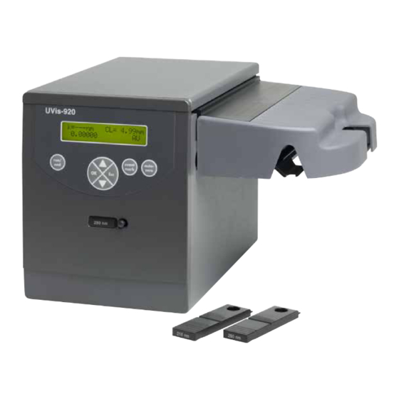
3 System description System description The Monitor UVis-920 is a UV and visible light absorption monitor which can be used in wavelengths range between 200-700 nm by changeable fixed wavelength filters. The instrument contains no internal user replaceable items. Illustrations... -
Page 21: Monitor Principle
The light enters an interference filter based monochromator which includes a collimating system and a filter unit with a fixed specific wavelength. It is possible to select wavelength between 200-700 nm by changing filter unit. Monitor UVis-920 Operating Instructions 29055049 AD... - Page 22 50% being directed through the reference fiber (R). Two photodiodes with identical characteristics monitor the intensities of the measuring and reference beams. Part Function Flash lamp 100 Hz Filter unit Beam Monitor UVis-920 Operating Instructions 29055049 AD...
-
Page 23: Flow Cell Principle
The precision of monitoring is enhanced by the construction of the flow cell, which ensures total reflectance of light. This maintains a high intensity of light to the detector. The long path length combined with a small cell volume increases sen- sitivity. Monitor UVis-920 Operating Instructions 29055049 AD... -
Page 24: Installation
4 Installation Installation About this chapter This chapter provides required information to enable users and service personnel to unpack, install, move and transport Monitor UVis-920. Precautions WARNING Before attempting to perform any of the procedures described in this chapter, you must read and understand all contents of the Safety instructions chapter. -
Page 25: Unpacking
The instrument should not be used in a corrosive atmosphere or in an atmosphere where deposits are liable to form on the optical surfaces. Transport Before moving the equipment: disconnect all connected cables and tubing. Monitor UVis-920 Operating Instructions 29055049 AD... -
Page 26: Installing The Cell Holder
If UV Flow Cell, 2 mm or UV Flow Cell, 10 mm is to be used the flow cell holder included in the UVis-920 delivery must be installed. Step Action Illustration Unpack the cell holder. - Page 27 To improve the access to the tubing connec- tions the cell can be positioned with the text and se- rial number facing upwards or sideways. Press the cell into the clips to fasten it. Monitor UVis-920 Operating Instructions 29055049 AD...
- Page 28 High intensity UV light. This product uses high intensity ultra-violet light. Do not disconnect the optical fibers while the lamp is on. NOTICE Do not touch the tips of the optical fiber with anything other than lens paper. Monitor UVis-920 Operating Instructions 29055049 AD...
- Page 29 Remove the two black protective caps from the opti- cal fiber connectors. Remove the two rubber protective caps from the optical fiber receptacles on the right side of the housing. Part Function Protective cap Rubber sleeve Black shrinking tube Monitor UVis-920 Operating Instructions 29055049 AD...
- Page 30 Remove the red protective caps from the inlet and outlet of the flow cell and connect the tubing with 1/16" fingertight connectors. Mount the cell holder cover by pushing it onto the cell holder. Monitor UVis-920 Operating Instructions 29055049 AD...
- Page 31 Connect the inlet and outlet tubing to the flow cell. Connecting the optical fibers WARNING High intensity UV light. This product uses high intensity ultra-violet light. Do not disconnect the optical fibers while the lamp is on. Monitor UVis-920 Operating Instructions 29055049 AD...
- Page 32 To avoid damaging the optical fibers, press only on the cell body, never on the optical fibers. Step Action Remove the two protective rubber caps from the optical fiber connectors of Monitor UVis-920. Part Function Protective cap Transmitter Knurled nut Reciever Monitor UVis-920 Operating Instructions 29055049 AD...
-
Page 33: Connecting Electrical Cables
Attach this connector to the flow cell by carefully inserting it into the socket and tightening the nut fingertight (fits only one of the two sockets). Attach the other connector to the transmitter connector of Monitor UVis-920. Do not overtighten. - Page 34 The signal cable is delivered with protective covers on each wire. Do not remove the protective covers from unused connections as a short circuit may disturb the measurements. Set the recorder to 0 V to 1 V input, full scale, 0 V offset. Monitor UVis-920 Operating Instructions 29055049 AD...
- Page 35 Auto Zero (In) Negative edge zeroes AU-value Common ground for all signals Error (Out) Goes low at error. Goes high again when OK is pressed State (Out) 0=UVis-920 is in Run-mode 1=UVis-920 is in End-mode Monitor UVis-920 Operating Instructions 29055049 AD...
- Page 36 Connect a mains cable between the instrument and a grounded mains socket. The instrument is delivered with both European and US type mains cables, as standard. Any voltage 100 V to 240 VAC, 50 Hz to 60 Hz, can be used. Monitor UVis-920 Operating Instructions 29055049 AD...
-
Page 37: Operation
5 Operation Operation About this chapter This chapter provides the information required to safely operate Monitor UVis-920. Precautions WARNING Before attempting to perform any of the procedures described in this chapter, you must read and understand all contents of the Safety instructions chapter. -
Page 38: Menu Selection
Follow local and/or national regulations for safe operation and maintenance of Monitor UVis-920. 5.1.1 Monitor UVis-920 front panel Operation menu and settings are selected by the membrane keys at the front of Monitor UVis-920. Monitor UVis-920 Operating Instructions 29055049 AD... -
Page 39: Menu Navigation
5.1.2 Menu navigation A specific menu is selected by the front arrow down key. When the required menu is visible, the menu or selection is accepted by pressing the OK key. Monitor UVis-920 Operating Instructions 29055049 AD... - Page 40 If a menu has sub levels, the sub menu is displayed by pressing the OK key. Pressing the Esc key moves back one menu level. Main menu Sub menus Main operating Setup Sub menu Sub menu Check Sub menu Sub menu Sub menu Sub menu Monitor UVis-920 Operating Instructions 29055049 AD...
- Page 41 If the new value to be set is within brackets, it is possible to select between a number of preset values. No brackets make it possible to select step by step within a preset range, for example 0-999. Monitor UVis-920 Operating Instructions 29055049 AD...
-
Page 42: Turning The Monitor On And Off
2 The instrument starts and displays the main operating window. For optimum perfor- mance 30 minutes warm-up time is recommended. To setting a run timer or end timer is another way to switch the Xenon-lamp on/ off. See Setting run and end timers, on page Monitor UVis-920 Operating Instructions 29055049 AD... -
Page 43: Main Menu Overview
The instrument can measure absorbance at wavelengths between 200-700 nm by changeable filter units. The wavelength currently used is shown in main operating menu. When no filter is inserted the display shows λ= - - - nm. Monitor UVis-920 Operating Instructions 29055049 AD... -
Page 44: Custom Filters
Insert a custom filter. The display shows Change Wave Length. Select yes to set wavelength, press OK. Select no, press Esc to return to main displau If yes, enter the wavelength of custom filter in nanometer. Press OK. Monitor UVis-920 Operating Instructions 29055049 AD... -
Page 45: Autozero
Setting range and zero UVis-920 displays the measured absorbance value as an analog voltage in the recorder connector. The output from the instrument is always 0 V to 1 V, but the absorbance value for full scale deflection (AUFS) and the zero absorbance level on the recorder can be set. - Page 46 0 V when reaching maximum but is instead clipped and hold at the maximum (see illustration below). The overrange is managed in the same way when the signal reaches the minimum. a) Automatic overrange enabled b) Automatic overrange disabled Monitor UVis-920 Operating Instructions 29055049 AD...
- Page 47 Peaks narrower than the minimum peak width value may be distorted. Because of this the averaging time should be as short as possible, see the table below. On delivery the averaging time is set to 2.56 s. Step Action Display Select menu Set Averaging Time, press OK. Monitor UVis-920 Operating Instructions 29055049 AD...
- Page 48 If the value is correct, use the arrow keys to go to next menu. If the value has to be changed, press OK to change it. Select menu Set Cell Path Length, press OK. Monitor UVis-920 Operating Instructions 29055049 AD...
- Page 49 0. If timer is enabled by OK, the re- maining minutes to run are shown. Press Esc key to return to the RunTimer End Timer menu which now shows the countdown time and end time. Setting unit number For service use only. Monitor UVis-920 Operating Instructions 29055049 AD...
-
Page 50: Check Menu
----- is shown. The serial value is shown number must be 1000 or higher. Check analog output The function of the connected chart recorder can be tested. Step Action Display Select menu Check, press OK. Select menu Check Analog Out, press OK. Monitor UVis-920 Operating Instructions 29055049 AD... - Page 51 This menu shows how many hours the filter has been used, i.e. the time in running mode. There is one time counter for each filter wavelength. Step Action Display Select menu Check, press OK. Monitor UVis-920 Operating Instructions 29055049 AD...
-
Page 52: 5.10 Uv Cell Calibration
Lamp used time Step Action Display Select menu Check, press OK. Select menu Filter Used Time, press OK. If the lamp used time is > 4000 hours, contact GE for lamp replacement. Stop the test by pressing Esc. Software version Step Action Display Select menu Check, press OK. -
Page 53: 5.11 Changing Flow Cell
Section 4.5 Installing the flow cells, on page 26. Data for up to five flow cells are saved in memory in Monitor UVis-920. 5.12 Restart after power failure If the power supply to the instrument is interrupted, the instrument automatically restarts itself and displays the main operating menu. -
Page 54: Maintenance
Maintenance Monitor UVis-920 does not require any periodic maintenance. About this chapter This chapter provides required information to enable users and service personnel to clean and maintain Monitor UVis-920. The instrument contains no internal user replace- able parts. Precautions WARNING... -
Page 55: Cleaning Before Planned Service
6.1 Cleaning before planned service WARNING Use only approved parts. Only spare parts and accessories that are approved or supplied by GE may be used for maintaining or servicing the product. NOTICE The mains power to Monitor UVis-920 must be switched off before connecting the instrument to any cells or external equipment. - Page 56 After five squirts, leave the detergent solution in the flow cell for at least 20 minutes. Pump the remaining detergent solution through the flow cell. Rinse the syringe and flush the cell with distilled water (10 ml). Monitor UVis-920 Operating Instructions 29055049 AD...
-
Page 57: Storage
The flow cell can also be stored dry by flushing as above with distilled water and then blowing a compressed inert gas such as nitrogen (N ) through the cell. Replace the pro- tective caps. Never use compressed air as this may contain droplets of oil. Monitor UVis-920 Operating Instructions 29055049 AD... -
Page 58: Troubleshooting
This chapter provides information required to enable users and service personnel to identify and correct problems that may occur when operating Monitor UVis-920. If the suggested actions in this guide do not solve the problem, or if the problem is not covered by this guide, contact your GE representative for advice. -
Page 59: General
7 Troubleshooting 7.1 General General When contacting GE for support, state the program version of the instrument, which is shown in the check menu. See Software version, on page 52 Faults and actions If the suggested actions do not correct the fault, call GE. -
Page 60: Error Messages
7 Troubleshooting 7.3 Error messages Error messages If the suggested actions do not correct the fault, call GE. Message Description/Action Cell/fiber fail Check the connections of the UV cell optical fibers. Check the liquid. Ensure that there are no air bubbles in the system. -
Page 61: Reference Information
0.1 M sulphuric acid Short term noise (0.5–1 min) < 2x10 AU at 280 nm 1, 2 Long term noise (1–10 min) < 2x10 AU at 280 nm Drift < 2x10 AU/h at 280 nm Monitor UVis-920 Operating Instructions 29055049 AD... - Page 62 < 70 dB A UV flow cell, 2 and 10 mm Recommended maximum flow 100 ml/min rate Maximum pressure 2 MPa (20 bar, 290 psi) Backpressure Maximum 0.5 bar at 2 ml/min with water at 25°C Monitor UVis-920 Operating Instructions 29055049 AD...
- Page 63 Optical path length 1, 2 and 5 mm Cell volume 300 μL Wetted materials PEEK (polyetheretherketone) Titanium (palladium alloy) FFKM (perflorelastoner) or EPDM Quartz (synthetic fused silica) pH stability range 1–13, 13–14 (< 1 days exposure) Monitor UVis-920 Operating Instructions 29055049 AD...
- Page 64 Tubing connections TC25 connector Industrial flow cell 1" Recommended maximum flow rate Maximum pressure 1 MPa (10 bar, 145 psi) up to 40°C Backpressure Max. 0.4 bar at 600 l/h with water at 25°C. Monitor UVis-920 Operating Instructions 29055049 AD...
- Page 65 The wetted parts are resistant to organic solvents and salt buffers commonly used in chromatogra- phy of biomolecules, except 100% ethyl acetate, 100% hexane, and 100% tetrahydrofuran (THF) or 15% THF in acetonitrile Tubing connections TC50 connector Monitor UVis-920 Operating Instructions 29055049 AD...
-
Page 66: Health And Safety Declaration Form
Service Ticket #: To make the mutual protection and safety of GE service personnel and our customers, all equipment and work areas must be clean and free of any hazardous contaminants before a Service Engineer starts a repair. To avoid delays in the servicing of your equipment, please complete this checklist and present it to the Service Engineer upon arrival. - Page 67 To make sure the mutual protection and safety of GE personnel, our customers, transportation personnel and our environment, all equipment must be clean and free of any hazardous contaminants before shipping to GE. To avoid delays in the processing of your equipment, please complete this checklist and include it with your return.
-
Page 68: Accessories And Spare Parts
8 Reference information 8.3 Accessories and spare parts Accessories and spare parts UV monitor Item Quantity per pack Code no. Monitor UVis-920 complete without flow cell 11000754 and without filter Flow cells Item Quantity per pack Code no. UV Flow Cell 2 mm , including optical fibres... - Page 69 PEEK tubing, i.d. 0.75 mm, o.d. 1/16" 18111253 PEEK tubing, i.d. 1.0 mm, o.d. 1/16" 18111583 ETFE tubing, i.d. 0.25 mm, o.d. 1/16" 18112136 ETFE tubing, i.d. 0.75 mm, o.d. 1/16" 18111254 Fingertight connector 1/16" 18111255 Monitor UVis-920 Operating Instructions 29055049 AD...
- Page 70 8 Reference information 8.3 Accessories and spare parts Tools Item Quantity per pack Code no. Fiber detachment tool 18111116 Monitor UVis-920 Operating Instructions 29055049 AD...
- Page 71 751 84 Uppsala All goods and services are sold subject to the terms and conditions of sale of the company within GE Healthcare which supplies them. A copy of these terms Sweden and conditions is available on request. Contact your local GE Healthcare repre- sentative for the most current information.