Table of Contents
Advertisement
Quick Links
Advertisement
Table of Contents

Related Manuals for GE Responder 2000


Summary of Contents for GE Responder 2000
- Page 1 Operator’s Manual 2026116-001 Revision B English...
- Page 2 REVISION HISTORY Part Number and Revision Date Comment 2026116-001 Revision A October 2006 Initial Release 2026116-001 Revision B November 2006 Minor changes: Update page 18 to identify “Rotary Selector knob” not “button”.
-
Page 3: Table Of Contents
CABLE (OPTIONAL FEATURE)..........30 INSTALLING PAPER INTO THE PRINTER ................. 31 POWERING THE RESPONDER 2000 ................. 32 RESPONDER 2000 FRONT AND BACK CONTROLS AND INDICATORS ......33 RESPONDER 2000 SIDE CONTROLS AND INDICATORS ............. 33 RESPONDER 2000 SIDE CONTROLS AND INDICATORS ............. 34 Z-BAR™... - Page 4 INFORMATION (OPTIONAL) .................43 PACING INFORMATION (OPTIONAL) ................43 ON-SCREEN INDICATORS....................44 BATTERY INDICATOR.....................44 BATTERY WARNING MESSAGES................44 HEART RATE ........................45 SECTION 3: USING THE RESPONDER 2000 ................47 OVERVIEW..........................47 RESPONDER 2000 PREPARATION..................48 PATIENT PREPARATION ......................48 USING PADS ........................48 APPLYING PADS ......................49 SPECIAL PAD PLACEMENT SITUATIONS ..............49 ANTERIOR-LATERAL PLACEMENT OF PADS FOR DEFIBRILLATION/SYNC SHOCK (MOST COMMONLY USED)................50...
- Page 5 AUDIBLE ALARMS ....................... 79 ADJUSTING HEART RATE ALARM LIMITS ................80 SETTING THE ECG SOURCE AND GAIN ................80 SECTION 4: CONFIGURING THE RESPONDER 2000 SETTINGS ..........81 OVERVIEW..........................81 SETTINGS MENU ......................... 82 TO VIEW THE SETTINGS MENU ..................82 DEFIBRILLATION SETTINGS ....................
- Page 6 DEFAULT SETTINGS.....................106 SECTION 5: MAINTENANCE & SERVICE.................107 OVERVIEW..........................107 RECOMMENDED MAINTENANCE AND CARE ..............108 VISUAL INSPECTION......................109 CLEANING RESPONDER 2000 AND ACCESSORIES .............110 RECOMMENDED CLEANING PRODUCTS...............110 CLEANING INSTRUCTIONS ....................110 PRINTER CLEANING INSTRUCTIONS ................111 PADDLE AND INTERNAL PADDLE CLEANING INSTRUCTIONS ........111 INTERNAL PADDLE STERILIZATION INSTRUCTIONS ...........111 INSERTING THE SPOON ELECTRODE................111...
- Page 7 ELECTROMAGNETIC IMMUNITY TABLE................130 RF COMMUNICATIONS TABLE .....................132 EN 60601-1-2 COMPLIANCE ....................133 COMPLIANT CABLES AND ACCESSORIES ..............133 SECTION 7: ACCESSORIES......................135 OVERVIEW..........................135 RESPONDER 2000 ACCESSORIES ..................136 SECTION 8: CONTACT INFORMATION/CUSTOMER SERVICE ..........139 OVERVIEW..........................139 CONTACT INFORMATION / CUSTOMER SERVICE .............140 2026116-001 Revision B Responder™ 2000...
- Page 8 2026116-001 Revision B Responder™ 2000 Page 8...
-
Page 9: Section 1: Introduction
OVERVIEW This operator’s manual provides instructions for the safe and proper operation, as well as set-up, configurations, and maintenance information. Be sure to familiarize yourself with the operation of the Responder 2000 prior to its use. TOPIC PAGE # RESPONDER 2000 DESCRIPTION... -
Page 10: Responder 2000 Description
), built-in 60 mm thermal printer, internal storage of event history and remote synchronization to bedside monitor. The Responder 2000 is suitable for indoor use only. It is not intended for use in vehicles or aircrafts. 2026116-001 Revision B Responder™ 2000... -
Page 11: Indications For Use/Intended Use
INDICATIONS FOR USE/INTENDED USE The Responder 2000 defibrillator system is intended to be used by personnel who have been trained in its operation. The Responder 2000 is indicated for the termination of certain fatal arrhythmias, such as ventricular fibrillation and symptomatic ventricular tachycardia. -
Page 12: Safety Terms And Conditions
SAFETY TERMS AND CONDITIONS The following is a list of Responder 2000 safety alerts that appear in this section and throughout this manual. You must read, understand, and heed these safety alerts before attempting to operate the Responder 2000. The signal words shown below identify the potential hazard categories. The definition of each category is as follows: DANGER: This alert identifies hazards that will cause serious personal injury or death. - Page 13 WARNING: If the integrity of the external power earth conductor arrangement is in doubt, unplug the device from the mains AC and operate it from a Responder 2000 rechargeable battery that is charged. WARNING: The Responder 2000 will not power on if AC power is lost when the battery is low or not inserted in the Responder 2000.
- Page 14 WARNINGS (CONTINUED) WARNING: When the patient is a child under 8 years of age or weighs less than 55 lbs (25kg), the Responder 2000 should be used with pediatric defibrillation pads. Therapy should not be delayed to determine the patient’s exact age or weight.
-
Page 15: Precautions
PRECAUTION: Recycle or dispose of the lithium-ion battery in accordance with your country’s regulations. To avoid fire and explosion hazard, do not burn or incinerate the battery. PRECAUTION: Prior to disposal, remove the batteries from the Responder 2000. Then dispose of the device in accordance with your country’s regulations for equipment containing electronic parts. - Page 16 Avoid operating the Responder 2000 near cauterizers, diathermy equipment, FM 2-way radios, or cellular phones. Turn power off to radio, cellular and other like equipment near the Responder 2000. Refer to the EMI tables in section 6. PRECAUTION: Possible Interference with Implanted Pacemaker Therapy should not be delayed for patients with implanted pacemakers and a defibrillation attempt should be made if the patient is unconscious and not breathing.
- Page 17 PRECAUTION: Moving the Patient while Responder 2000 is attached During a rescue attempt, excessive jostling or moving of the patient may cause the Responder 2000 to improperly analyze the patient’s cardiac rhythm. Stop all motion or vibration before attempting to use the Responder 2000.
-
Page 18: Notes
NOTE: Verify printer has adequate paper on its roll for use. NOTE: To change the password, see TO CHANGE THE PASSWORD in this section of the manual. NOTE: All changes to the settings of the Responder 2000 must be performed before connecting the Responder 2000 to the patient. -
Page 19: Symbol Descriptions
SYMBOL DESCRIPTIONS The following symbols may appear in this manual, on the Responder 2000, or on its accessories. Some of the symbols represent standards and compliances associated with the Responder 2000 and its use. Consult instructions for use of the Responder 2000 and/or its accessories. - Page 20 Power button: When pressed, turns the Responder 2000 on and off. This symbol also indicates when the Responder 2000 has power. The enclosure of the Responder 2000 is protected against the ingress of dripping water in IP22 accordance with EN 60529. The enclosure of the Responder 2000 is protected against ingress of solid foreign objects greater or equal to 12.5 mm in accordance with EN 60529.
-
Page 21: Safety And Performance Standards
IEC 60601-2-4 (2002) Section 36 ANSI/AAMI DF-80(2003) Section 36 The Responder 2000 needs to be installed and put into service according to the EMC information specified in this manual. Refer to Section 6 of this manual for a complete list of all Safety Standards. -
Page 22: Operator Training Requirements
NOTE: Keep valid certificates of training and certification as required by state, province, or country regulations. WARNING: The Responder 2000 is not intended to be deployed in settings or situations that promote use by untrained personnel. Operation by untrained personnel can result in injury or death. -
Page 23: Section 2: Getting Started
SECTION 2: GETTING STARTED OVERVIEW This section presents information on unpacking and setting up the Responder 2000 TOPIC PAGE # UNPACKING AND INSPECTING SETTING UP THE RESPONDER 2000 RECHARGEABLE BATTERY INSTALLATION AND REMOVAL USING THE BATTERY CHARGER CONNECTING PADDLES OR PADS... -
Page 24: Unpacking And Inspecting
Check the components according to the packing list. • Check for any damage or defects. Do not attempt to setup the Responder 2000 if anything is damaged or defective. Contact Customer Service immediately if anything is damaged or defective. 2026116-001 Revision B Responder™... -
Page 25: Setting Up The Responder 2000
SETTING UP THE RESPONDER 2000 This section provides the basic set up information you need to prepare the Responder 2000 for operation and to connect the optional monitoring accessories. RECHARGEABLE BATTERY INSTALLATION AND REMOVAL The Responder 2000 uses a rechargeable battery. The rechargeable battery is not shipped fully charged and it is recommended that you charge the battery fully before using. -
Page 26: To Remove The Battery
Press the battery release until the battery ejects. Pull the battery straight out until it clears the housing. WARNING: The Responder 2000 should not be stored with the battery inserted. Remove the battery from the Responder 2000 when storing the device. -
Page 27: Using The Battery Charger
USING THE BATTERY CHARGER With a new battery at room temperature, the Responder 2000 will first indicate “Low Battery” while there is still sufficient charge remaining to perform at least five (5) rescues. As the battery ages, there will be progressively less operating time available before low battery warning, after low battery warning before therapy inhibit, and after therapy inhibit before system shutdown. -
Page 28: The Battery Calibration Cyle
CHARGING BATTERY WHILE INSIDE THE RESPONDER 2000 Connect the supplied power cord to the socket at the rear of the Responder 2000 then plug in to a suitable AC power source. The battery will automatically charge when the power cord is connected to the Responder 2000. The battery will take up to eight hours to charge in the Responder 2000. -
Page 29: Connecting Paddles Or Pads
STORING THE PADDLES The paddles dock easily on each side of the Responder 2000. Simply push and click to secure as shown in Figure 2.2 below. The paddles can be docked with the cables pointing up or down as preferred. -
Page 30: Connecting The Ecg Leads
CONNECTING THE ECG LEADS The Responder 2000 accepts either 3-lead or 5-lead ECG cables. Align the ECG connector with the green port in front Responder 2000. Push the ECG cable firmly into the ECG port. Once the ECG connector is attached, a 3-lead or 5-lead wire can be connected to the other end of the cable as shown in Figure 2.3 below. -
Page 31: Installing Paper Into The Printer
INSTALLING PAPER INTO THE PRINTER To install paper into the printer, follow these instructions. Lift up on the front printer flap as shown by arrow on the Responder 2000. Pull door flap up and forward to open the printer. Place paper roll into the printer with the paper end pulled over the top of the printer roller through the opening in the printer door. -
Page 32: Powering The Responder 2000
POWERING THE RESPONDER 2000 The Responder 2000 operates safely from the following power sources: • Rechargeable battery • AC power using the supplied power cord 2026116-001 Revision B Responder™ 2000 Page 32... -
Page 33: Responder 2000 Front And Back Controls And Indicators
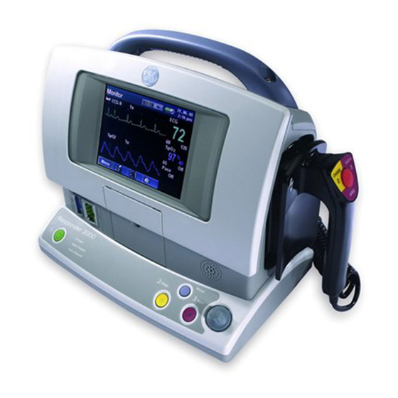
RESPONDER 2000 FRONT AND BACK CONTROLS AND INDICATORS Graphics Display Thermal Printer Speaker Cable port port (Optional) Power ON/Off Button Rotary Selector Status LEDS Charge Button Knob Manual Button Shock Button Handle Paddle/Pad Port Bed Rail Hooks (optional accessory) RS-232 Data... -
Page 34: Responder 2000 Side Controls And Indicators
RESPONDER 2000 SIDE CONTROLS AND INDICATORS SIDE 1 SIDE 2 Paddle Dock Rechargeable Battery 2026116-001 Revision B Responder™ 2000 Page 34... -
Page 35: Z-Bar™ Indicator
• Pad or Paddle quality and integrity • Pad or Paddle adhesion to the patient’s skin • Pad or Paddle connection to the Responder 2000 • Provides for quick assessment between OFF and SHORTED Z-BAR FOR PADS AND PADDLES SECTION... -
Page 36: Buttons
Manual Button POWER BUTTON To Power on and off the Responder 2000, push the green Power button on the front panel of the Responder 2000. POWER ON Press the green power button to turn on the Responder 2000. As the Responder 2000 powers on, the system performs a self-test. -
Page 37: Charge Button
CHARGE BUTTON The charge button is used to manually charge the Responder 2000 to the selected energy level. This button is only used in Manual Mode. This button is disabled when paddles are connected to the Responder 2000. In this case, the Responder 2000 will be charged only from the paddle charge button. -
Page 38: Manual Button
MANUAL BUTTON The manual buttons brings the operator in or out of the Manual Mode Screen, which allows the operator to begin or end a shock sequence. If the manual button is pushed during Pacing, the operator needs to confirm entry of Manual Mode before Manual Mode is entered. -
Page 39: Rotary Selector Knob
(b) selecting soft keys and (c) setting values. This knob is the primary operator navigation and selection vehicle for the Responder 2000. It can rotate clockwise and counterclockwise. To make a selection, press the Rotary Selector Knob. The knob is always active while the system application is running. -
Page 40: Status Leds
When the paddles are connected to the Responder 2000, the charge and shock buttons on the front panel will be disabled. -
Page 41: Graphics Display
The monitor screen contains the information bar, Channel 1 and 2 waveforms, information areas for ECG, Pacing and areas. INFORMATION BAR At the top of the screen is the Information bar showing the operating mode of the Responder 2000, the impedance display, a battery charge status indicator and the current date and time. MESSAGE AREA In the middle of the screen, the Responder 2000 displays messages for software and system errors. -
Page 42: Channel 1
CHANNEL 1 If 3-lead or 5-lead ECG cables are connected to the Responder 2000, the ECG monitoring waveform is displayed in Channel 1. The same waveform can be cascaded (continued) from Channel 1 to Channel 2 if desired. Typically, the system will display the power-on default of ECG II until a different lead combination is chosen. -
Page 43: Information Areas
INFORMATION AREAS The right side of the screen contains specific monitoring information for ECG (top box), SpO (Oximetry) and Pacing if these two options are present. To access the information areas: Rotate the Rotary Selector Knob until the outline of the information box is highlighted then press to select the information area. -
Page 44: On-Screen Indicators
When the Responder 2000 is connected to AC, a "lightning bolt" indicates that the battery is being charged or charge is being maintained if the battery is full. When AC is not present, no lightning bolt is displayed. -
Page 45: Heart Rate
The heart rate display is updated once every 2 seconds. The Responder 2000 will respond to a change in heart rate from eighty (80) bpm to one hundred and twenty (120) bpm in less than five (5) seconds. - Page 46 2026116-001 Revision B Responder™ 2000 Page 46...
-
Page 47: Section 3: Using The Responder 2000
SECTION 3: USING THE RESPONDER 2000 OVERVIEW This section describes how to prepare the Responder 2000 and the patient and using the Responder 2000. TOPIC PAGE # RESPONDER 2000 PREPARATION PATIENT PREPARATION USING PADS USING ECG ELECTRODES USING EXTERNAL PADDLES... -
Page 48: Responder 2000 Preparation
USING PADS The Pads listed in Section 7 of this manual are compatible with the Responder 2000. Adhere to the Precaution and Warnings, Applying PADS, Placement of PADS, Changing of PADS, PADS OFF or SHORTED notifications in this section. -
Page 49: Applying Pads
• To ensure proper rhythm analysis by the Responder 2000, patient preparation and hook up must be properly performed. Proper application and placement of the pads are essential for high-quality ECG monitoring. Good contact between the pad and skin minimizes motion artifact and signal interference. -
Page 50: Anterior-Lateral Placement Of Pads For Defibrillation/Sync Shock (Most Commonly Used)
ANTERIOR-LATERAL PLACEMENT OF PADS FOR DEFIBRILLATION/SYNC SHOCK (MOST COMMONLY USED) Turn off the Responder 2000. Connect the pads connector to the Responder 2000. Shave the application points; this improves conductivity and makes the removal of pads easier. Remove the protective liner by starting with the pad cable connection end. Slowly peel back the protective liner from the pads. -
Page 51: Anterior-Posterior Placment Of Pads For Non-Invasive Pacing And Defibrillation/Sync Shock
ANTERIOR-POSTERIOR PLACMENT OF PADS FOR NON-INVASIVE PACING AND DEFIBRILLATION/SYNC SHOCK Turn off the Responder 2000. Connect the pads connector to the Responder 2000. Shave the application points; this improves conductivity and makes the removal of pads easier. Remove the protective liner by starting with the pad cable connection end. Slowly peel back the protective liner from the PADS. -
Page 52: Changing Pads
ECG to ECG II, if this feature is activated from the settings. To go back to pads/paddles ECG you have to switch back manually. WARNING: Due to the unique impedance characteristics of the patient, the Responder 2000 may not be able to shock the patient. -
Page 53: Using Ecg Electrodes
Attach the ECG patient cable lead wires to the ECG electrodes. The lead wires are color coded according to AHA or IEC standards. Plug the ECG patient cable into the ECG input connector (green) located on the front panel of the Responder 2000. Prepare the patient’s skin according to the Patient Preparation section in this manual. - Page 54 USING ECG ELECTRODES (CONTINUED) 3-Lead Placement RA/R placement: Directly below the clavicle and near the right shoulder LA/L placement: Directly below the clavicle and near the left shoulder LL/F placement: On the left lower abdomen 5-Lead Placement RA/R placement: Directly below the clavicle and near the right shoulder LA/L placement: Directly below the clavicle and near the left shoulder RL/N placement: On the right lower abdomen LL/F placement: On the left lower abdomen...
-
Page 55: Using External Paddles
WARNING: Use only paddles specified in Section 7 of this manual. The use of unapproved equipment may cause the Responder 2000 to malfunction and may hinder patient treatment. WARNING: Risk of Skin Burns / Equipment Damage — Do not apply the paddles over sternum or clavicle, nipples, implanted pacemaker or defibrillator devices. - Page 56 Now trigger the shock within 30 seconds. To do so, simultaneously press the buttons (A) and (B) on the paddles. NOTE: When the patient is a child under 8 years of age or weighs less than 55 lbs (25 kg), the Responder 2000 should be used with Pediatric Defibrillation paddles and pediatric energy protocols.
- Page 57 WARNING: Shock Hazard – Always switch off the device before exchanging the defibrillation electrodes and internal spoons. NOTE: If you are using internal electrodes with the Responder 2000, defibrillator charging and shock delivery must be initiated with corresponding buttons on the front panel of the Responder 2000.
-
Page 58: Inserting The Spoon Electrode
INSERTING THE SPOON ELECTRODE • Screw the counter nut 2 onto the electrode as far as it will go. • Screw the contact paddle 1 into the handle as far as it will go, then bring it into the appropriate position. •... -
Page 59: Defibrillator Application Guidelines
DEFIBRILLATOR APPLICATION GUIDELINES Observe the following guidelines to ensure successful and safe defibrillation. Otherwise the lives of the patient, the user and bystanders are in danger. WARNING: Defibrillating a patient with normal heart rhythm may induce ventricular fibrillation. WARNING: Position the patient flat on a hard surface where he is electrically insulated. The patient must not be allowed to come into contact with metal parts to prevent unwanted pathways for the defibrillation current which may endanger the assistants. -
Page 60: Defibrillation Modes
DEFIBRILLATION MODES The Responder 2000 has two (2) modes of defibrillation, each with a customized display view. The modes are as follows: Manual Mode Operator manually selects energy level appropriate for the patient’s age, manually charges the unit, and manually delivers therapy to the patient. In this mode, energy can be selected manually or by using the auto-sequence energy settings. -
Page 61: Manual Mode
Manual Mode can be selected from the System Menu or by pressing the Manual button. If Manual Mode is set as the default mode, the Responder 2000 will power up in Manual Mode after turning the Responder 2000 on. It will then flash the yellow Charge button. - Page 62 Warn bystanders to stand clear of the patient. Ensure that you do not touch the patient. After the Responder 2000 is charged, push and hold the Shock button(s) until therapy is delivered. The message Shock Delivered displays for eight (8) seconds once the shock has been delivered.
-
Page 63: No Sync/Sync Option
After a shock is delivered, the Responder 2000 automatically selects the next energy level. After all three pre-set shocks have been delivered; the Responder 2000 selects the last energy level. All shocks after the third shock will be at that level. -
Page 64: Semi-Auto Shock Mode
Use of spoons is not be allowed in Semi-Auto Shock Mode. If spoons are attached to the Responder 2000 during power on, selection of Semi-Auto Mode, or while already in Semi-Auto mode, the device will automatically switch to Manual Mode immediately. - Page 65 TO USE SEMI-AUTO SHOCK MODE (CONTINUED) Press the Rotary Selector Knob to Analyze. If a shockable rhythm is detected, the Responder 2000 will automatically charge to the appropriate energy level. The sequence starts with the first displayed value then increments through the three increasing values.
-
Page 66: Ecg Monitoring
ECG MONITORING This section describes the basic ECG monitoring functions of the Responder 2000. The Responder 2000 can be used for ECG monitoring. The monitoring function allows the operator to monitor through: • Pads • 3-lead ECG Electrodes • 5-lead ECG Electrodes If both pads and monitoring electrodes are connected, monitoring allows you to select a lead from the 3-lead, 5-lead ECG source, or to monitor through the pads. -
Page 67: Monitoring Pacemaker Patients
When monitoring the heart rate of pacemaker patients, only the patient's QRS complexes must be counted and pacer pulses must be rejected. For this purpose, the Responder 2000 has an electronic pacer pulse suppression algorithm which rejects the pacer pulses so they are not counted as QRS complexes. Depending on the pacemaker model used and on the position of the electrodes, the compensation pulse following every pacer pulse may be considered as a QRS complex. -
Page 68: Non-Invasive Pacing (Option)
PRECAUTION: If the battery is removed while pacing and there is not AC Power, the pacing settings need to be re-set when the battery is inserted again. NOTE: The message “Please wait” will be displayed during the period when the Responder 2000 is not pacing, because of change of lead. The Responder 2000 will not pace during this time. -
Page 69: To Use Pacing Mode
Turn the pacemaker OFF Disconnect pace pads from the Responder 2000. Remove pace pads from patient. If monitoring of the patient is no longer required, turn off the Responder 2000. Remove ECG electrodes from patient. 2026116-001 Revision B Responder™ 2000... -
Page 70: Guidelines For The Application Of External Pacemakers
Expert knowledge, good organization and special care in selecting the technical installation as well as regular maintenance are required to ensure such operating conditions. Medical electrical devices such as the Responder 2000 must only be handled by persons who are trained in the use of such equipment and are capable of applying it properly. -
Page 71: Demand Pacing
As a general rule, check the ECG signal quality before turning the pacer on. In the presence of excessive electrode-skin contact impedance, the signal quality may drop to a level which the Responder 2000 interprets as a lead fail condition. As a result the device will display a dashed line and switch from demand pacing to the fixed-rate pacer mode or to pacer PAUSE mode. - Page 72 The device defaults to the Demand mode and selects a pacer rate of 60 PPM (configurable). Select the Pacing Info Box by turning the Rotary Selector Knob. Turn pacer on. Select a low pacer current output, e.g. 20mA Select the required pacer rate. Now increase the pacer current output slowly until the heart reliably responds to the stimulation.
-
Page 73: Fixed-Rate Pacing
FIXED-RATE PACING WARNING: During fixed-rate pacing, heart rate and heart rate alarms are suppressed. Therefore, the operator shall check for the patient’s pulse rate, not the heart rate. PRECAUTION: The pacer pulses are delivered via the adhesive defibrillation electrodes. Separate electrodes can be applied for acquisition of the ECG signal. -
Page 74: Pulse Oximetry (Option)
The Responder 2000 SpO can be monitored in all operating modes. A pulse oximetry sensor sends light through patient tissue to a receiver on the other side of the sensor. -
Page 75: Application Tips
APPLICATION TIPS General Tips • Use only the probes listed in chapter 7 "Accessories". Apply the probes as described in their instructions for use. Carefully observe all information and cautions given in these instructions. • Take care that the probe does not exert too much pressure when applied to avoid erroneous readings and blistering. Inadequate oxygen supply to the skin, not heat, causes blisters. -
Page 76: Printing
PRINTING The Responder 2000 allows the operator to print the channel waveform and associated information. The print starts with waveform data four (4) seconds prior to the initiation of the print sequence and will automatically stop after twenty (20) seconds (default) or run continuously. -
Page 77: Snapshot
HISTORY MENU From the history menu the operator can view the event log and patient trends. EVENT LOG The Responder 2000 logs patient events, operator actions, and system errors and warnings. This information can be viewed or printed. • Logged Events show the name, event code, time of occurrence and associated information with the event. -
Page 78: Responding To Alarms
• Battery low indication 10-beep High priority audible alarm, repeating every 5 seconds. (Beep-beep-beep…beep-beep…… beep-beep-beep…beep-beep) These alarms do not occur when the Responder 2000 is initially powered on. MEDIUM PRIORITY ALARMS Med Priority Alarms are generated by the following: •... -
Page 79: Visual Alarm Displays
To attract attention, the background edge of the highlight flashes every second while the alarm is active. AUDIBLE ALARMS The Responder 2000 has a speaker built in to the front panel of the device to sound audible alarms when appropriate. •... -
Page 80: Adjusting Heart Rate Alarm Limits
ADJUSTING HEART RATE ALARM LIMITS Rotate Rotary Selector Knob and select Heart Rate Alarm Rotate Rotary Selector Knob and Select Low Alarm Limit Range Available Low Alarm Settings: Off, 25-120 (in increments of 5) Default: 40 Press Rotary Selector Knob to confirm setting Rotate Rotary Selector Knob and Select High Alarm Limit Range Available Settings: 40-300 (increments of 5), Off Default: 180... -
Page 81: Section 4: Configuring The Responder 2000 Settings
SECTION 4: CONFIGURING THE RESPONDER 2000 SETTINGS OVERVIEW The Responder 2000 features a flexible configuration set-up. Menus with controls and options specific to each function of the Responder 2000 are easily accessible and configurable through the Menu Select and Rotary Selector Knob located on the front panel. -
Page 82: Settings Menu
SETTINGS MENU The Settings Menu allows customization to the Responder 2000 settings, which means that they are retained in memory and are activated automatically when you power on the device. The Settings Menu allows you to make adjustments to view the following settings. - Page 83 TO VIEW THE SETTINGS MENU (CONTINUED) Push the Rotary Selector Knob A password may be required to change the settings. To enter the password, push the Rotary Selector Knob. It will highlight the first space. There is no default password. If a password needs to be reset, enter VASCULAR 2026116-001 Revision B...
- Page 84 11. After successfully entering the password, the Setting menu will now appear. NOTE: To change the password, see TO CHANGE THE PASSWORD in this section of the manual. NOTE: All changes to the settings of the Responder 2000 must be performed before connecting the Responder 2000 to the patient.
-
Page 85: Defibrillation Settings
DEFIBRILLATION SETTINGS The Responder 2000 Defibrillation Settings can be configured to the desired setting. From the Settings menu, rotate the Rotary Selector Knob to Defibrillation Settings. Push the Rotary Selector Knob to view Defibrillation Settings. Turn the Rotary Selector Knob to highlight the desired setting. -
Page 86: Default Shock Energy Settings
DEFAULT SHOCK ENERGY SETTINGS The Default Shock Energy Settings menu allows default settings to be selected for Manual Mode, Auto Sequence Mode and Use Auto Sequence. Manual Mode Auto Sequence Mode Use Auto Sequence Mode Factory Default: 150 Joules Factory Default: 200, 200, 270 Joules Factory Default: Yes Available Settings: 2, 3, 5, 7,10,15, Available Settings for first, second and... -
Page 87: Pacing Settings
PACING SETTINGS The Responder 2000 Pacing settings can be configured to the desired setting from the Settings or Pacing mode box on the startup menu. Pacing mode is turned off by default. TO CHANGE PACING SETTINGS FROM SETTINGS MENU From the Settings menu, rotate the Rotary Selector Knob to Pacing Settings and push Rotary Selector Knob to select. -
Page 88: To Change Settings From Startup Menu
TO CHANGE SETTINGS FROM STARTUP MENU From the startup menu, use Rotary Selector Knob to move focus to Pacing mode box in the bottom right hand side of the menu. Press the Rotary Selector knob to change the Pacing Settings. After selecting the desired pacing mode, current, and rate settings, turn the selector knob to highlight the Pacing mode box and press the rotary knob to confirm the settings. -
Page 89: Channel Settings
CHANNEL SETTINGS The Responder 2000 Channel Settings can be configured to the desired setting. From the Settings menu, rotate the Rotary Selector Knob to Channel Settings. Push the Rotary Selector Knob to view Channel Settings. Turn the Rotary Selector Knob to highlight the desired setting. -
Page 90: Channel 1
CHANNEL 1 The Channel 1 menu allows default settings to be selected for Source and Gain. Source Auto-switch Source Factory Default: ECG II Factory Default: Off Available Settings: ECG 1, ECG II, ECG III, aVR, aVF, aVL, Available Settings: On, Off V, Paddles Gain Factory Default: 1x... -
Page 91: Alarms/Sound Settings
ALARMS/SOUND SETTINGS The Responder 2000 Alarm/Sound Settings can be configured to the desired setting. From the Settings menu, rotate the Rotary Selector Knob to Alarms/Sound Settings. Push the Rotary Selector Knob to view Alarms/Sound Settings. Turn the Rotary Selector Knob to highlight the desired setting. -
Page 92: Audio Defaults
AUDIO DEFAULTS Audible Alarm Volume Pulse Beep Factory Default: Off Factory Default: Loud Factory Default: Soft Available Settings: On, Off Available Settings: Soft, Medium, Available Settings: Off, Soft, Loud Medium, Loud PATIENT TRIGGERS Low Heart Rate (BPM) High Heart Rate (BPM) Factory Default: 40 Factory Default: 180 Available Settings: Off, 25-120... -
Page 93: Date/Time Settings
DATE/TIME SETTINGS The Responder 2000 time, date, and date format can be configured to the desired setting. From the Settings menu, rotate the Rotary Selector Knob to Date/Time Settings. Press the Rotary Selector Knob to select Date/Time Settings. The Date/Time Settings screen will be displayed. - Page 94 Year format: YY Year Value: 04 through 99 Default Time Format: 24 Date Format: Hour Month/Day/Year, Year/Month/Day, Day.Month.Year Default Date Format: Day.Month.Year NOTE: The Responder 2000 does not automatically adjust the Date/Time for Daylight Savings. 2026116-001 Revision B Responder™ 2000 Page 94...
-
Page 95: User Settings Menu
USER SETTINGS MENU The Responder 2000 User Settings Menu allows you to store the name of your institution in the device and create a new password. From the Settings menu, rotate the Rotary Selector Knob to User Settings Menu. Push the Rotary Selector Knob to view User Settings Menu. -
Page 96: Facility
FACILITY The Facility menu allows you to store the name of the institution in the device. Push the Rotary Selector Knob to bring the cursor to the first space. Push the Rotary Selector Knob again to select the letter, number, punctuation. Turn the Rotary Selector Knob to scroll through the English only alphabet and numbers in this field. -
Page 97: Set Password
SET PASSWORD The Responder 2000 Set Password Menu allows you create a unique password. There is no default password. To open the Set Password menu, turn the Rotary Selector Knob to Set Password and press the Rotary Selector Knob. Push the Rotary Selector Knob to bring the cursor to the first space. -
Page 98: System Settings Menu
SYSTEM SETTINGS MENU The Responder 2000 System Settings menu allows you to configure display, printer, power-up settings as well as restoring Responder 2000 defaults. From the Settings menu, rotate the Rotary Selector Knob to System Settings Menu. Push the Rotary Selector Knob to view System Settings Menu. -
Page 99: Display Settings
DISPLAY SETTINGS The Responder 2000 Display Settings menu allows you to configure the backlight of the graphics display. From the Settings menu, rotate the Rotary Selector Knob to Display Settings Push the Rotary Selector Knob to view Display Settings settings. - Page 100 DISPLAY SETTINGS (CONTINUED) Turn the Rotary Selector Knob to select the desired value. Default Value: Bright Available Settings:Dim, Medium, Bright After selecting desired setting, push the Rotary Selector Knob. Turn the Rotary Selector Knob to Accept. Press the Rotary Selector Knob. 2026116-001 Revision B Responder™...
- Page 101 PRINTER SETTINGS The Responder 2000 Printer Settings menu allows you to configure printer options. From the Settings menu, rotate the Rotary Selector Knob to Printer Settings Push the Rotary Selector Knob to view Printer Settings settings. Turn the Rotary Selector Knob to highlight the desired setting.
- Page 102 User Intitiated Print Option Duration Event Initiated Print Option Factory Default: 20 seconds Factory Default: Shock 20 Seconds Available Settings: 20 seconds, Continuous Available Settings: Shock 20 Seconds, Auto 20 Seconds, Auto Continuous, Off 2026116-001 Revision B Responder™ 2000 Page 102...
-
Page 103: Power-Up Settings
POWER-UP SETTINGS The Responder 2000 Power-up Setting’s menu allows you to configure and set the default mode. From the Settings menu, rotate the Rotary Selector Knob to Power-Up Settings Push the Rotary Selector Knob to view Power-Up Settings. Turn the Rotary Selector Knob to highlight the desired setting. -
Page 104: Power-Up Mode Default
POWER-UP MODE DEFAULT Power up Mode Default: Manual Mode Available Settings: Manual Mode, Semi-Auto Mode, Monitor Mode Press the Rotary Selector Knob. After selecting desired default settings, turn the Rotary Selector Knob to Accept. Press the Rotary Selector Knob. 2026116-001 Revision B Responder™... -
Page 105: Restore Defaults
RESTORE DEFAULTS The Responder 2000 Restore Defaults menu allows you to restore all settings to factory recommended defaults. From the Settings menu, rotate the Rotary Selector Knob to Restore Defaults Settings Push the Rotary Selector Knob to view Restore Defaults Settings settings. -
Page 106: Default Settings
DEFAULT SETTINGS When the Restore Defaults option is selected, the settings will be changed to the factory defaults as specified in the table below. NOTE: Change power-up default in Menu, do not change on display. Item Factory Default Display: Channel 1 Source ECG II Display: Channel 1 Gain Display: Channel 2 Source... -
Page 107: Section 5: Maintenance & Service
SECTION 5: MAINTENANCE & SERVICE OVERVIEW Proper maintenance of the Responder 2000 is very simple, yet it is an important factor in its reliability. This section describes the maintenance and service required for the Responder 2000 and its accessories. TOPIC... -
Page 108: Recommended Maintenance And Care
• It is important that the Responder 2000 is stored at the operating temperature range if it is expected to be used. Optimal battery life will be obtained if stored and operated at room temperature. See Section 7 for Temperature Specifications. -
Page 109: Visual Inspection
VISUAL INSPECTION The Responder 2000 and its accessories should be carefully inspected prior to installation, daily, and each time the equipment is serviced. • Carefully inspect the equipment for physical damage • Inspect all external connections for loose connectors or frayed cables. -
Page 110: Cleaning Responder 2000 And Accessories
Defibrillator Checklist in this manual and cleaned when appropriate. Listed below are recommendations for cleaning the Responder 2000 and its accessories. RECOMMENDED CLEANING PRODUCTS The following cleaning products may be used to clean the exterior surfaces of the Responder 2000 as well as the batteries: •... -
Page 111: Printer Cleaning Instructions
Use the cleaning products recommended for cleaning of the Responder 2000 unit. Before applying the paddles again, check that they have thoroughly dried. -
Page 112: External Counter Electrode For Internal Defibrillation
When the battery no longer holds a charge, it should be replaced. This condition may occur after 2.5 years or 300 charge/discharge cycles. The batteries are recyclable. Remove the old battery from the Responder 2000 and follow your local recycling guidelines. -
Page 113: Defibrillator Checklist
The following daily checklist is recommended to be utilized when checking the defibrillator: INSTRUCTIONS CORRECTIVE ACTION Inspect Responder 2000 housing for: Ensure that it is clean, free from spills, clear of Clean the device if necessary objects, housing intact, and there are no signs of visible damage. - Page 114 If this is not the case, please contact Press Manual button again and verify Manual Mode Customer Service. is entered. Verify Power cable connected to Responder 2000 No Action Verify AC Power LED is turned on. If this is not the case, please contact Customer Service.
- Page 115 Defibrillator Testing: A discharge test can be triggered to check the defibrillator discharge circuit. For this test the stored energy is discharged into the Responder 2000 via two contacts in the paddle cradle. WARNING: Equipment Damage Do not trigger more than five (5) consecutive test discharges (or internal safety discharges) within thirty (30) minutes.
- Page 116 SpO 2 Testing (if Responder 2000 has this option) No Action Connect desired SpO 2 cable and connector combination to Responder 2000 and apply sensor to a test person. If SpO is displayed not plausible, Verify SpO 2 is plausible please contact Customer Service.
-
Page 117: Authorized Repair Service
AUTHORIZED REPAIR SERVICE The Responder 2000 has no user-serviceable internal components. Try to resolve any maintenance issues with the Responder 2000 by using the Troubleshooting Table presented in this chapter. If you are unable to resolve the problem, contact Customer Service. - Page 118 2026116-001 Revision B Responder™ 2000 Page 118...
-
Page 119: Section 6: Specifications & Safety
SECTION 6: SPECIFICATIONS & SAFETY OVERVIEW This section presents the specifications and safety standards of the Responder 2000. TOPIC PAGE # SPECIFICATIONS PHYSICAL DIMENSIONS ENVIRONMENTAL REQUIREMENTS RHYTHMx® ECG ANALYSIS ALGORITHM STAR® BIPHASIC DEFIBRILLATION WAVEFORM ELECTROMAGNETIC COMPATIBILITY REQUIREMENTS ENVIRONMENTAL STANDARDS ELECTROMAGNETIC EMISSIONS TABLE... -
Page 120: Specifications
SPECIFICATIONS DISPLAY Size: 115.2mm X 86.4mm Type: Transmissive Color TFT LCD Resolution: 320 X 240 pixels Number of waveform channels: DEFIBRILLATOR Waveform: Biphasic truncated exponential Charge Time: 7 seconds nominal Delivery Method: Via pads, paddles or spoons Paddles and Pads Energy Selections (50Ω 2, 3, 5, 7, 10, 15, 20, 30, 50, 70, 100, 150, 200, 270 load): Internal Paddle Energy Selections (50Ω... - Page 121 Battery Capacity: 50 shocks, or 240 minutes monitoring time, or 72 minutes monitoring time with pacing Battery Charge Time: 8 hours in Responder 2000, 4 hours in external charger, 20 hours for calibration cycle in external charger Battery Standby: 6 months Battery Life: 2.5 years or 300 Battery charge-discharge cycles, whichever comes first...
-
Page 122: Physical Dimensions
PRECAUTION: Cold Environments If the Responder 2000 is stored in an environment with a temperature below the operating temperature, the unit should be allowed to warm up to the needed operating temperature before using. 2026116-001 Revision B Responder™... -
Page 123: Rhythmx Ecg Analysis Algorithm
• Continuous Monitoring The Responder 2000 rejects all T-waves that are 1 millivolt or less in the conditions specified in ANSI/AAMI EC 13 section 4.1.2.1c. The Responder 2000 will alarm tachycardia in the conditions specified in ANSI/AAMI EC 13 section 4.1.2.1 g) in less than 10 seconds. -
Page 124: Sync Mode
The pacer pulse detector will not respond to the waveform of ANSI/AAMI figure 5d, since this waveform is below the threshold of the Responder 2000 pacer pulse detector. The minimum typical slew rate in V/s RTI that will trip the pacer detector is 6.2 V/s for the 3 and 5 lead ECG. -
Page 125: Star ® Biphasic Defibrillation Waveform
® STAR BIPHASIC DEFIBRILLATION WAVEFORM The waveform generated by the Responder 2000 is a BIPHASIC TRUNCATED EXPONENTIAL waveform that is compliant with ANSI/AAMI DF80. ® STAR Biphasic Waveform – 270J into Pads or paddles Table A - 270J Waveform into Different Resistive Loads (Typical Values) Patient’s... -
Page 126: Energy Levels And Patient Impedance
ENERGY LEVELS AND PATIENT IMPEDANCE The Biphasic Truncated Exponential (BTE) waveform delivers energy that is variant with the patient impedance. The waveform is designed to deliver the selected energy when the patient impedance is 50 Ohms, as shown in the above waveform table. -
Page 127: Safety Standards And Compliance Requirements
Defibrillators (including automated external defibrillators) ELECTROMAGNETIC COMPATIBILITY REQUIREMENTS The Responder 2000 meets the requirements of the following EMC standards, as required by IEC 60601-2-4.: IEC 60601-1-2 (2001), Medical electrical equipment Part 1: General requirements for safety 2. Collateral standard: electromagnetic compatibility - Requirements and tests. -
Page 128: Environmental Standards
ENVIRONMENTAL STANDARDS SHOCK AND VIBRATION The Responder 2000 is tested per the following when in the unpackaged condition: Bump: IEC 60068-2-29 (1987), Test EB: bump; 25g, 6 ms, 0.9 m/s ∆V, and 1000 bumps in each direction Sine Vibration: IEC 60068-2-6 (1995), Environmental testing - part 2. tests - test FC: Vibration (sinusoidal); 0.15mm... -
Page 129: Electromagnetic Emissions Table
ELECTROMAGNETIC EMISSIONS TABLE Guidance and manufacturer’s declaration – electromagnetic emissions The Responder 2000 is intended for use in the electromagnetic environment specified below. The customer or the user of the Responder 2000 should assure that it is used in such an environment. -
Page 130: Electromagnetic Immunity Table
ELECTROMAGNETIC IMMUNITY TABLE Guidance and manufacturer’s declaration – electromagnetic immunity The Responder 2000 is intended for use in the electromagnetic environment specified below. The customer or the user of the Responder 2000 should assure that it is used in such an environment. - Page 131 Guidance and manufacturer’s declaration – electromagnetic immunity The Responder 2000 is intended for use in the electromagnetic environment specified below. The customer or the user of the Responder 2000 should assure that it is used in such an environment. Compliance...
-
Page 132: Rf Communications Table
To assess the electromagnetic environment due to fixed RF transmitters, an electromagnetic site survey should be considered. If the measured field strength in the location in which the RESPONDER 2000 is used exceeds the applicable RF compliance level above, the RESPONDER 2000 should be observed to verify normal operation. -
Page 133: En 60601-1-2 Compliance
The use of accessories, transducers and cables other than those specified in Section 7 of this manual may increase emissions or decrease immunity performance of the device/system. The table below lists cables, transducers, and other applicable accessories with which GE Medical Systems claims EMC compliance. - Page 134 2020387-003 Power cord, Argentina 2.5 m / 8 ft 2020387-004 Power cord, Denmark 2.5 m / 8 ft 2020387-005 Power cord, India & South Africa 2.5 m / 8 ft 2020387-006 Power cord, Italy 2.5 m / 8 ft 2020387-007 Power cord, Japan 2.5 m / 8 ft 2020387-008...
-
Page 135: Section 7: Accessories
SECTION 7: ACCESSORIES OVERVIEW This section contains a list of parts and accessories for Responder 2000. To place an order, contact your representative or distributor. TOPIC PAGE # RESPONDER 2000 ACCESSORIES 2026116-001 Revision B Responder™ 2000 Page 135... -
Page 136: Responder 2000 Accessories
RESPONDER 2000 ACCESSORIES Responder 2000 is available in more than twenty languages, with others being added on a regular basis. For a complete list of those available, contact your sales representative or Customer Service. WARNING: The use of accessories and cables other than those specified may result in increased emissions or decreased immunity of the equipment. - Page 137 ECG ACCESSORY KITS Part Number Description 2025269-007 3-lead Accessory Kit, AHA 2021141-001 Multi-Link 3-Lead ECG Cable with Integrated Grabber Leadwires, AHA, 12 ft (3.6m) 60-mm thermal paper (1 roll; 1/50 of 2026327-001) ECG Electrodes; round, foam (one (1) 30-electrode pouch); 1/10 of 2014786-001 2025269-008 5-lead Accessory Kit, AHA 2017003-001...
- Page 138 OTHER ACCESSORIES Part Number Description 2025267-001 Rechargeable battery, GE-branded 2027556-001 Battery charger with North American power cord 2027556-002 Battery charger with European power cord 2027556-003 Battery charger with Argentina power cord 2027556-004 Battery charger with Denmark power cord 2027556-005 Battery charger with India & South Africa power cord...
-
Page 139: Section 8: Contact Information/Customer Service
SECTION 8: CONTACT INFORMATION/CUSTOMER SERVICE OVERVIEW This section contains a list of parts and accessories for Responder 2000. To place an order, contact your representative or distributor. TOPIC PAGE # CONTACT INFORMATION / CUSTOMER SERVICE 2026116-001 Revision B Responder™ 2000... -
Page 140: Contact Information / Customer Service
CONTACT INFORMATION / CUSTOMER SERVICE To order supplies or accessories, contact your representative or distributor. For technical support, contact your local GE customer service. Please have the serial and model numbers available. The serial and model numbers are located on the back of the Responder 2000. - Page 141 2026116-001 Revision B Responder™ 2000 Page 141...
- Page 142 Section 7: Accessories 2026116-001 Revision B Responder™ 2000 Page 142...