Table of Contents
Advertisement
Quick Links
Advertisement
Table of Contents

Related Manuals for Fluke IRCON ScanIR3


Summary of Contents for Fluke IRCON ScanIR3
- Page 1 ScanIR3 Linescanner Operating Instructions Rev. A1 Mar 2015 60901...
- Page 3 +1 831 458 – 3900 Fax: +1 831 458 – 1239 info@ircon.com European Headquarters Berlin, Germany Tel: +49 30 4 78 00 80 info@ircon.eu Fluke Service Center Beijing, China Tel: +86 10 6438 691 Tel: +86 10 4008103435 (Service) info@ircon.com.cn Internet: http://www.ircon.com/...
- Page 4 ARRANTY The manufacturer warrants this instrument to be free from defects in material and workmanship under normal use and service for the period of two years from date of purchase. This warranty extends only to the original purchaser. This warranty shall not apply to fuses, batteries, or any product which has been subject to misuse, neglect, accident, or abnormal conditions of operation.
-
Page 5: Table Of Contents
Content CONTENT ................................5 1 SAFETY INSTRUCTIONS ..........................7 2 TECHNICAL DATA ............................10 2.1 M ....................... 10 EASUREMENT PECIFICATIONS 2.2 O .......................... 11 PTICAL PECIFICATIONS 2.2.1 Optical Diagrams ..........................13 2.3 E ........................14 LECTRICAL PECIFICATIONS 2.4 G ......................... 14 ENERAL PECIFICATIONS 2.5 D... - Page 6 7.3 T ............................39 ITTINGS 7.3.1 Installation of the Tube Fittings ......................39 7.3.2 Reassembly of the Tube Fittings ......................39 7.4 S ............................40 PARE INDOWS 7.5 R IR2 C ................41 EPLACEMENT IT FOR OOLING OUSING 7.6 F / RJ45 E .....................
-
Page 7: Safety Instructions
Safety Instructions 1 Safety Instructions This document contains important information, which should be kept at all times with the instrument during its operational life. Other users of this instrument should be given these instructions with the instrument. Updates to this information must be added to the original document. The instrument can only be operated by trained personnel in accordance with these instructions and local safety regulations. - Page 8 Safety Instructions Safety Symbols AC (Alternating Current) DC (Direct Current) Hazardous voltage Risk of danger. Important information. See manual Helpful information regarding the optimal use of the instrument Earth ground Protective ground Fuse Normally-open (NO) relay Normally-closed (NC) relay Switch or relay contact DC power supply CAT I Measurement Category I...
- Page 9 Safety Instructions To prevent possible electrical shock, fire, or personal injury follow these guidelines: Read all safety information before you use the product. • Use the product only as specified, or the protection supplied by the product can be • compromised.
-
Page 10: Technical Data
Technical Data 2 Technical Data 2.1 Measurement Specifications Temperature Range S330 20 to 350°C (68 to 662°F) S339 100 to 800°C (212 to 1472°F) S335 100 to 650°C (212 to 1202°F) S350 100 to 950°C (212 to 1742°F) S34x 30 to 250°C (86 to 482°F) – for S343 100 to 350°C (212 to 662°F) –... -
Page 11: Optical Specifications
Technical Data Temperature Resolution digital interface 0.1 K analog output 16 bit Scan Rate All models 150 Hz in steps of: 20 Hz, 36 Hz, 48 Hz, 76 Hz, 85 Hz, 108 Hz, 126 Hz, 150 Hz Measured Points per Line All models 256 pixel @ 150 Hz scan rate 512 pixel @ 76 Hz scan rate... - Page 12 Technical Data Figure 1: Optical Resolution for Measurement Resolution depending on Scan Rate Figure 2: Optical Resolution for Hot Spot Detection depending on Scan Rate ScanIR3 Rev. A1 Mar 2015...
-
Page 13: Optical Diagrams
Technical Data 2.2.1 Optical Diagrams The focus distance is measured from the front end of the scanner! Figure 3: Diagrams for selected Optical Resolutions (90% energy) ScanIR3 Rev. A1 Mar 2015... -
Page 14: Electrical Specifications
Technical Data 2.3 Electrical Specifications Communications Ethernet TCP/IP protocol 10/100 MBit/s, electrically isolated auto-negotiation Inputs Trigger + 5 to 24 VDC pulse, high/low active Functional Input max. + 5 VDC function depends on the specific linescanner system Signal Processing Stand-alone unit Max, Min, Average, Peak/Valley Hold, Alarm setpoints further signal processing function through software Power... -
Page 15: Dimensions
Technical Data Head Cable Cable material FEP (oil resistant) Cable gland stainless steel (1.4305 / AISI 303) Ambient temperature -50 to 180°C (-58 to 356°F) Outer diameter 11.3 mm (0.44 in) Minimal bending radius 135 mm/5.3 in (moved) 85 mm 3.3 in (non-moved) Processor Box Temperature Range 0 to 50°C (32 to 122°F);... -
Page 16: Scope Of Delivery
Technical Data Ø 8.7 mm (0.34 in) Figure 5: Footprint for the Processor Box 2.6 Scope of Delivery The linescanner package includes the following: ScanIR3 Linescanner with head cable • Processor box with internal power supply • Operating Instructions (also included as PDF file on the CD-ROM) •... -
Page 17: Basics
Basics 3 Basics 3.1 Measurement of Infrared Temperatures Every object emits an amount of infrared radiation (IR) according to its surface temperature. The intensity of the infrared radiation changes with the temperature of the object. Depending on the material and surface properties, the emitted radiation lies in a wavelength spectrum of approximately 1 to 20 µm. -
Page 18: System Overview
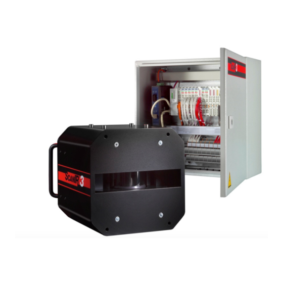
System Overview 4 System Overview The following figure shows the principal structure of the system. It shows a system with a linescanner, the sensor cable and the processor box. The processor box supports the interfacing capabilities like analog or digital outputs and provides optionally glass fiber communication. Linescanner Sensor Cable Processor Box... -
Page 19: Installation
Installation 5 Installation 5.1 Pre-Installation The following guidelines will help in planning the installation of the scanner system. When this instrument is being used in a critical process that could cause property damage and personal injury, the user should provide a redundant device or system that will initiate a safe process shut-down in the event that this instrument should fail. -
Page 20: Mounting
Installation 2. Hot spots must be clearly detected, when in front of a cold background (50% energy response). Remark: The measured area for 50% energy response is approximately ⅓ of the area size of the measured spot for 90% energy response. Refer to section 2.2 Optical Specifications, page 11, for basic versions of optical resolution values for... -
Page 21: Wiring
Installation 5.3 Wiring 5.3.1 Overview Prior to making any wiring connections ensure that AC power is off! The processor box provides power and communication to the linescanner. For the processor box there are several output modules available offering analog or digital signals to the central control system see section 6.2 Sectors, page 35. - Page 22 Installation AC Mains Scanner Head Cable Modules 100 – 240 VAC 50/60 Hz Figure 9: Terminal Line ScanIR3 Rev. A1 Mar 2015...
-
Page 23: Cable Entry System
Installation 5.3.2 Cable Entry System The cable entry system is a split system that allows pre-assembled cables to be routed into the system connection box without disassembling the connectors. Snap-on mounting Lay cable into appropriate grommet and provide strain relief where necessary using cable ties. -
Page 24: Scanner Head Cable
Installation 5.3.3 Scanner Head Cable The scanner head cable comes pre-wired to the processor box by factory default. Terminal Color Description Figure 10: Wiring the Scanner Head Cable By standard, the cable gland is mounted to the scanner head cable. In case of specific installation needs, see the mounting structure for the cable gland below for detaching/attaching it. -
Page 25: Input/Output Modules
Installation 5.3.4 Input/Output Modules The processor box contains a terminal line which is labeled like shown below. It shows the maximal stage of expansion for the output modules from the wiring point of view. Due to limited space, the maximal number of modules is restricted to 11! 21 22 23 24 25 26 27 28 29 30 31 32 33 34 35 36 37 38 39 40 41 42 43 44 45 46 47 48 49 50 51 52 53 54 55 56 57 58 59 60 6 Output Modules, analog 6 Output Modules, Relay... - Page 26 Installation Terminal Figure 13: AC Mains Cable The Earth Ground wire should be slightly longer than the two other wires so if the cable is accidentally pulled the line and neutral wires are disconnected first. You need to connect the AC mains. Use only cable with 3 wires in a size of 1.5 to 2.5 mm² (AWG 14 to 16).
-
Page 27: Communication Interfaces
Installation 5.4 Communication Interfaces The linescanner communicates via Ethernet interface. The Ethernet connection between linescanner and the PC has a maximum speed of 100 MBit/s and permits real-time data transfer for all temperature pixels. For multi-scanner systems you can use a standard Ethernet Switch to connect to the PC network adapter. -
Page 28: Changing The Ethernet Settings For The Pc
Installation The current settings for the IP address and the netmask of the PC can be asked with the command <ipconfig> in a Command Prompt window! For the example above, the IP address of the PC is 193.221.142.103. The subnet address is 193.221.142, the host address is 103. - Page 29 Installation 3. Under <This connection uses the following items> select <Internet Protocol (TCP/IP)> and click on <Properties>: 4. Activate the radio button <Use the following IP address> and make the following settings: IP address: 192.168.42.x where x is an address between 0 and 255 except 30 which is already used by the linescanner by factory default Subnet mask: 255.255.255.0...
-
Page 30: Changing The Ethernet Settings For The Scanner
Installation 5.4.3 Changing the Ethernet Settings for the Scanner When using the linescanner on an Ethernet network you may need to change the IP address so that the factory default address does not conflict with another device on the network. Change the IP address following the procedure described below: Make sure that the PC network adapter is configured as required, see sections 5.4.1 Ethernet... -
Page 31: Warm-Up Time
Installation 5.5 Warm-Up time For accurate temperature readings we recommend a 30 minute warm-up period after power on. During this time the internal calibration sources will be stabilized. Digital communication and the analog outputs can be started 60 seconds after power on. 5.6 Water Cooling The linescanner is equipped with integrated stainless-steel pipes for water cooling. - Page 32 Installation Relative Humidity [%] 100/ 100/ Tab. 2: Minimum device temperatures [°C/°F] Example: Temperatures higher than 55°C (131°F) Ambient temperature = 50 °C are not recommended due to the Relative humidity = 40 % temperature limitation of the device. Minimum device temperature = 30 °C The use of lower temperatures is at your own risk! ScanIR3...
-
Page 33: Air Purge Collar
Installation 5.7 Air purge collar The air purge system produces a laminar air flow that protects the linescanner window from dust, moisture, and vapor. The air flows from the couplings through the walls of the housing and through side slits near the scanner’s window. The air flow should be between 100 l/min (3.53 cfm) and 200 l/min (7.06 cfm) through each side, which corresponds to a pressure between 0.5 bar (7.25 psig) and 3.0 bar (43 psig) when using the supplied metric fittings. -
Page 34: Operation
Operation 6 Operation 6.1 Scan Rate and Target Viewing Time Optical scan rate = 150 Hz Distance between the actual measured lines (d), as Each revolution = 6,6 ms output, is a function of the optical scan rate, line Target viewed for 1,6 ms averaging and target speed. -
Page 35: Sectors
Operation 6.2 Sectors Via the processor box the linescanner is able to support multiple analog outputs. Each output can be assigned to a ”sector” within the 90° scan angle. For each sector, the type of result (maximum, minimum, or mean value) can be selected. Each sector result can drive an alarm output in case of violating a given threshold. -
Page 36: Data Transfer Modes
Operation The maximum size of a sector is 90°. • The corresponding analog output will remain inactive if the sector size is 0. • Each sector can have either a maximum, minimum, or mean output value. • Each sector is assigned to an analog interface. •... -
Page 37: Accessories
Accessories 7 Accessories 7.1 Overview A full range of accessories for various applications and industrial environments are available. Accessories include items that may be ordered at any time and added on-site. These include the following: Mechanical: Adjustable Mounting Base (S3X-RMB) •... -
Page 38: Adjustable Mounting Base
Accessories 7.2 Adjustable Mounting Base Figure 16: Adjustable Mounting Base (S3X-RMB) ScanIR3 Rev. A1 Mar 2015... -
Page 39: Tube Fittings
Accessories 7.3 Tube Fittings Description: 4x tube fittings - female adapter union (connects 6 mm outer diameter tube to conical thread Rc 1/8" (ISO7/1)) or 6 mm outer diameter tube to conical thread 1/8” NPT 7.3.1 Installation of the Tube Fittings The following steps explain the installation of the tube fittings to the stainless steel cooling tubes of the linescanner. -
Page 40: Spare Windows
Accessories 7.4 Spare Windows The available spare windows are listed in the table below. Each spare window includes a gasket. For replacing the spare window see the procedure described in section 8.3 Replacing the Window, page Spare Window Spectral Model S3X-SWK30 S330 S3X-SWK39... -
Page 41: Replacement Kit For Scanir2 Cooling Housing
Accessories 7.5 Replacement Kit for ScanIR2 Cooling Housing The S3X-REPKIT replacement kit is used to install a ScanIR3 Scanner in a legacy ScanIR2 Cooling Housing. To mount the scanner into the housing follow the steps given below. Mount the fittings on the scanner as shown in the figure. - Page 42 Accessories Drill two 11.5 mm (0.45 in) holes in the lid of the enclosure. The position of the holes can almost be chosen freely. Keep in mind to prevent collisions with other parts of the enclosure. Depending on the used tool for mounting shot-fittings, refractory needs holes in a particular...
- Page 43 Accessories Assemble the bulkhead fittings in the lid. Retrieve the alignment poles and mount them in the enclosure. ScanIR3 Rev. A1 Mar 2015...
- Page 44 Accessories Place the scanner cable in the notch. Put the scanner on the cooling plate and align it with the alignment poles. In order to integrate the internal cooling system of the scanner to the cooling system of the housing the connection between both cooling plates has to be opened.
-
Page 45: Fiber Optic / Rj45 Ethernet Converter
Accessories 7.6 Fiber Optic / RJ45 Ethernet Converter The Fiber Optic / RJ45 Ethernet Converter S3X-LWL (type Advantech EKI- 2541M) assures high reliability and stability in harsh environments, making it a robust bridge between enterprise fiberoptic backbones and Ethernet devices, like the ScanIR3 linescanner. -
Page 46: Maintenance
Maintenance 8 Maintenance If you need application assistance, calibration, repair, and solutions to specific problems our customer service representatives are always at your disposal. In many cases, problems can be solved over the telephone. If you need to return equipment to us, please contact our Service Department before doing so, please look at the address page for contact information. -
Page 47: Emoving The Dapter Ousing
Maintenance 8.1 Removing the Adapter Housing Remove the four M4x8 screws like shown in the figure. 4x M4x8 Cover Markings Figure 17: Removing the Adapter Housing Turn the scanner up side down and detach the four M6x10 screws. 4x M6x10 Figure 18: Removing the Adapter Housing ScanIR3 Rev. -
Page 48: Cleaning The Window
Maintenance 8.2 Cleaning the Window The linescanner’s window must be kept as clean as possible. Any foreign matter on the window will affect the accuracy of the measurements. Take care when cleaning the window as it can easily be scratched. Please observe the following guidelines: Lightly blow off loose particles. - Page 49 Maintenance Install the window assembly on the housing by alternating between the four screws. Do not over-tighten! Install the air purge collar on the housing! For correct temperature readings, the transmission factor for the new window must be set via the scanner runtime software, see menu <Scanner> <Transmissivity of the scanner window>! ScanIR3 Rev.
-
Page 50: Troubleshooting
Troubleshooting 9 Troubleshooting Checkpoint Possible Cause / Solution Scanner • Check the wiring of the whole system (correctly fitted connectors, cable damage). • Check the power for the scanner on scanner’s backside LED: green L is “on” • Check the rotation of the internal scanner mirror assuming the power is on (viewing or hearing test). - Page 51 Troubleshooting Checkpoint Possible Cause / Solution • Switch on/off the scanner’s power. • Software is not to be launched during the initialization time of the scanner (about 30 s). • Use the network administration utility Ping to test the reachability of the scanner. Call the Windows <Command Prompt>...
-
Page 52: Appendix
Appendix 10 Appendix 10.1 Determination of Emissivity Emissivity is a measure of an object’s ability to absorb and emit infrared energy. It can have a value between 0 and 1.0. For example a mirror has an emissivity less of 0.1, while the so-called “Blackbody“ reaches an emissivity value of 1.0. - Page 53 Appendix ETALS Material Emissivity 1 µm 1.6 µm 3.9 µm 5 µm Aluminum Unoxidized 0.1-0.2 0.02-0.2 0.02-0.2 0.02-0.2 0.2-0.4 0.2-0.4 Oxidized • Alloy A3003, Oxidized Roughened 0.2-0.8 0.2-0.6 0.1-0.4 0.1-0.4 Polished 0.1-0.2 0.02-0.1 0.02-0.1 0.02-0.1 Brass Polished 0.35 0.01-0.05 0.01-0.05 0.01-0.05 Burnished 0.65...
- Page 54 Appendix ETALS Material Emissivity 1 µm 1.6 µm 3.9 µm 5 µm Lead Polished 0.05-0.2 0.05-0.2 0.05-0.2 Rough • Oxidized 0.3-0.7 0.2-0.7 0.2-0.7 Magnesium 0.3-0.8 0.05-0.3 0.03-0.15 0.03-0.15 Mercury 0.05-0.15 0.05-0.15 0.05-0.15 Molybdenum Oxidized 0.5-0.9 0.4-0.9 0.3-0.7 0.3-0.7 Unoxidized 0.25-0.35 0.1-0.35 0.1-0.15 0.1-0.15...
- Page 55 Appendix ETALS Material Emissivity 1 µm 1.6 µm 5 µm Asbestos Asphalt 0.95 Basalt Carbon Unoxidized 0.8-0.9 Graphite 0.7-0.9 Carborundum Ceramic 0.8-0.95 Clay 0.85-0.95 Concrete 0.65 Cloth 0.4-0.9 0.95 Glass Plate 0.98 “Gob” Gravel 0.95 0.95 Gypsum 0.8-0.95 0.4-0.97 — Limestone 0.4-0.98 Paint (non-al.)