
Related Manuals for Weil-McLain 78


Summary of Contents for Weil-McLain 78
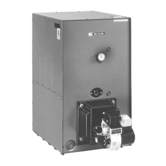
- Page 1 Boiler For Gas, Light Oil, Gas/Light Oil Fired Burners Boiler Manual • Installation • Start-Up • Maintenance • Parts...
-
Page 2: Table Of Contents
Contents Before Installing Boiler... page 3 Set Packaged Boiler or Block Assembly in Place... page 5 Assemble Block... page 6 Perform Hydrostatic Pressure Test... page 12 Connect Water Boiler Piping... page 13 Connect Steam Boiler Piping... page 15 Install Jacket ... page 19 Pipe Tankless Heaters... -
Page 3: Before Installing Boiler
Before Installing Boiler Installation must comply with: Before selecting boiler location: Provide combustion and ventilation air openings: Grating – Min. 12" above avg. snowline Note: GRADE Size of areaway and grating to be equal to or greater than total louver area. Areaway Louver Figure 1 Combustion and Ventilation Air... - Page 4 Before Installing Boiler Provide clearances for servicing around boiler: Boiler Model 2" Min. Lay a foundation, if needed: Boiler Foundation Length Table “L” Boiler Inches Model 1078 1178 1278 “L” 30" Figure 3 Boiler Foundation “L” Inches...
-
Page 5: Set Packaged Boiler Or Block Assembly In Place
Set Packaged Boiler or Block Assembly in Place For packaged boiler: For block assembly: Packaged Boiler Boiler Model Lbs. 1355 1615 1875 2130 2390 Lifting Weight Chart Assembled Packaged Block Boiler Boiler Lbs. Model 1150 1385 1620 1078 1855 1178 2090 1278 Assembled... -
Page 6: Assemble Block
Assemble Block Install back refractory blanket: Prepare back section: Sealing rope Cut off rope even with edge Cut off rope even with edge 3 1/2” Sealing ring Cut off rope even with edges Figure 4 7 1/2" Sealing ring Sealing rope Cut out observation... - Page 8 Assemble Block Prepare remaining sections: Section Arrangement Table Maximum Section Arrangement Boiler No. of (all heaters must be Model Heaters on left side of boiler) 378 W&S F-TI-B 478 W&S F-TI-I-B 578 W&S F-TI-I-TI-B 678 W&S F-TI-I-TI-I-B 778 W&S F-TI-I-TI-I-I-B 878 W&S F-TI-I-TI-I-I-TI-B 978 W&S...
- Page 10 Assemble Block Prepare flue collector hood assembly: Flat-stitched sealing rope Bend rope do not cut or stretch Flue collector hood end cap Figure 9 Sealing Rope Application on Collector Hood Assembly Double-faced tape applied to flange Extend rope 1/4" past open ends Flue collector hood modules...
- Page 11 Assemble Block Install flue collector hood assembly: Regular nut Flat washer Carriage bolt Figure 10 Holddown Clip Installation Flanged nut Holddown clip Flue collector hood Flat-stitched sealing rope Boiler sections...
-
Page 13: Connect Water Boiler Piping
Recommended Minimum Pipe Sizes for Known Flow Rates Water System Flow Rate supply (front only) Up to 35 36 to 50 51 to 77 78 to 142 Water meter valve ASME Drain Valve Size Boiler Model 378-478 578-1178 1278 Supply... -
Page 15: Connect Steam Boiler Piping
Connect Steam Boiler Piping General steam piping information: • Cold Check water fill Water meter valve Manual isolation valve Pressure reducing valve (when used) Manual isolation valve Figure 14 Cold Water Fill Piping Fig. Boiler Model 1078-1278 Install piping: To condensate return piping or condensate receiver... -
Page 24: Install Burner
Install Burner To install burner: Wiring and Fuel Piping To wire burner and boiler controls: To install gas and/or oil piping:... -
Page 25: Make Final Adjustments
Make Final Adjustments To fill water boilers: To fill steam boilers: Breeching damper Adjust burner and breeching damper: Test Plug Figure 29 Breeching Damper Adjustment Lock (Slide down to open damper) - Page 26 Make Final Adjustments Skim steam boilers: Determine if water treatment is needed (water boilers only): Check boiler for gas-tight seal:...
-
Page 27: Data And Dimensions
Data and Dimensions Supply Tappings Quantity And Size* Boiler Model Water Steam 2 - 4" 2 - 4" 2 - 4" 2 - 4" 2 - 4" 2 - 4" 2 - 4" 2 - 4" 2 - 4" 2 - 4" 2 - 4"... - Page 28 Data and Dimensions Minimum for heater removal 3" NPT 3" NPT return return Front Back Water line 4" NPT supply outlets W=Boiler section length Side Intermediate...
-
Page 29: Parts
Parts... - Page 30 Parts Figure No. Front Section (7813) Intermediate Section Regular (7815) Intermediate Section Supply - Steam (7814) Intermediate Section Tankless (7816) Back Section (7818) Section Assembly Kit adhesive, sealing rings, silicone sealant, tie rods, washers, nuts) Heater Cover Plate Carton Tankless Heater Carton Heater Gasket Cleanout Plate Cleanout Plate Gasket...
-
Page 31: Ratings
Ratings I=B=R Burner Capacity Gross Light I=B=R Output Boiler Model Net I=B=R Ratings Firebox Steam Steam Water Boiler Volume Sg. Ft. H.P. Cu. Ft. Boiler Water Content Gals. Positive Stack Presure I=B=R Vent Steam Volume Firebox Dia. In. W.C. Inches Water Waterline Packaged...