Table of Contents
Advertisement
Quick Links
CONTENTS
1. GENERAL ..................................................................... 1
2. INSTALLATION .......................................................... 2
3. CONNECTIONS ........................................................... 5
4. DSL SYSTEM TESTING ............................................. 5
5. OPERATION ................................................................. 7
6. DSL DEPLOYMENT GUIDELINES ........................ 12
7. MAINTENANCE ........................................................ 12
8. TROUBLESHOOTING PROCEDURES ................... 13
9. PRODUCT SPECIFICATIONS ................................. 13
10. WARRANTY AND CUSTOMER SERVICE ............ 13
Appendix A. FT1 Loopbacks ........................................ A-1
FIGURES
Total Access 1500 FT1 DP ........................... 1
FT1 DP DS0 Bantam Jack Diagram ............. 6
Main Menu Screen ......................................... 8
Current System Status Screen ....................... 9
Performance History Screen ........................ 10
Loopback Options Screen............................ 10
Provisioning Options Screen ....................... 11
DSL Deployment Guidelines ...................... 12
Figure A-1. FT1 Loopbacks ......................................... A-1
Figure A-2. FT1 DP Network Loopback ..................... A-1
Figure A-3. FT1 DP CPE Loopback ............................ A-1
Loopbacks ................................................. A-2
Figure A-5. FNID Network Loopback ......................... A-2
Figure A-6. FNID CPE Loopback................................ A-2
TABLES
Option Settings .............................................. 3
A/B Signalling Option Settings ..................... 4
Front Panel LEDs and Switches .................... 5
Definition of Screen Abbreviations ............... 7
Loop Insertion Loss Data ............................ 12
Troubleshooting Guide ................................ 13
FT1 DP Unit Specifications ........................ 14
Table A-1. FT1 Loopback Select Codes ..................... A-3
61180405L1-5A
Total Access
Total Access 1500 Fractional T1 Data Port
Installation and Maintenance
Section 61180405L1-5, Issue 1
Trademarks: Any brand names and product names included in this document are
trademarks, registered trademarks, or trade names of their respective holders.
®
1500 FT1 DP
FT1 DP
11804 05L1
7 8 9 10
6
11
5
12
4
DS1
3
2
DSL
SX
RX
REM
TX
LOGIC
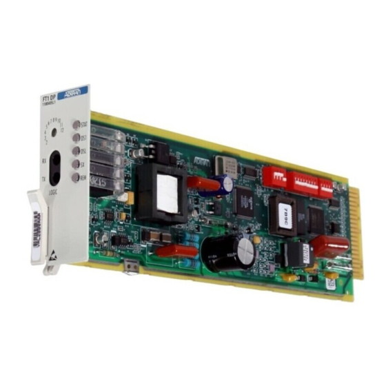
Figure 1. Total Access 1500 FT1 DP
1. GENERAL
This practice serves as an Installation and
Maintenance guide for the ADTRAN Total Access
1500 Fractional T1 Data Port (Total Access 1500 FT1
DP). Figure 1 is an illustration of the ADTRAN
Total Access 1500 FT1 DP, (P/N 1180405L1).
Revision History
This is the initial release of this document. Future
revisions to this document will be explained in this
subsection.
Description
The Total Access 1500 FT1 DP is the Central Office
unit used to deploy an FT1 circuit using 2-wire
metallic facilities. The Total Access 1500 FT1 DP
plugs directly into a standard Total Access 1500
channel bank. Signals are provided to and from the
channel bank while 2B1Q HDSL signals are provided
to the local loop.
Section 61180405L1-5A
Issue 1, November 2001
CLEI Code: VAL2BB0A_ _
1 2 3 4
1 2 3 4 5
6 7 8
1 2 3 4
1
Advertisement
Table of Contents

Related Manuals for ADTRAN Total Access 1500 FT1 DP


Summary of Contents for ADTRAN Total Access 1500 FT1 DP
-
Page 1: Table Of Contents
Front Panel LEDs and Switches ....5 Description Table 4. Definition of Screen Abbreviations ....7 The Total Access 1500 FT1 DP is the Central Office Table 5. Loop Insertion Loss Data ......12 Table 6. Troubleshooting Guide ........ 13 unit used to deploy an FT1 circuit using 2-wire Table 7. -
Page 2: Installation
The unit occupies two slots in a standard Total Access 1500 housing. No installation wiring is required. The payload between Total Access 1500 FT1 DP and FNID is programmable from the front panel rotary The bandwidth is taken by the Total Access 1500 FT1 switch as follows: DP in contiguous time slots. -
Page 3: Table 1. Option Settings
Options DIP Switch vs. Interface Options The FT1 DP is provisionable via the craft interface on Circuit board DIP switches SW1, SW2, and SW3 the Total Access 1500 SCU or by circuit board DIP select option configurations identical to interface switches. -
Page 4: Table 2. A/B Signalling Option Settings
Table 2. A/B Signalling Option Settings Function Description DIP Switch A/B Signalling for Channel 1: SW3-4 A/B Signalling Disabled* ......... Disables A/B Signalling in channel 1 ......OFF A/B Signalling Enabled ..........Enables A/B Signalling in channel 1 ......ON A/B Signalling for Channel 2: SW3-3 A/B Signalling Disabled* ......... -
Page 5: Connections
LED Indication 4. DSL SYSTEM TESTING The Total Access 1500 FT1 DP has five front panel The ADTRAN DSL system provides extensive ability LEDs that indicate operational status. Table 3 defines to monitor the status and performance of the DS1 these LEDs. -
Page 6: Figure 2. Ft1 Dp Ds0 Bantam Jack Diagram
A set of dual bantam jacks are on the front panel of The front panel of the FT1 DP has DS0 splitting the Total Access 1500 FT1 DP. The jacks allow for bantam jacks. The metallic splitting jacks provide an... -
Page 7: Operation
5. OPERATION For abbreviations used in the screen diagrams, see Table 4. Table 4. Definition of Screen Abbreviations Definition Abbreviation Errored Seconds: A count of the number of seconds in which at least one code violation was detected on a digital circuit ES .... -
Page 8: Figure 3. Main Menu Screen
The FT1 DP Main Menu is accessed via a craft port The following screens can be accessed from the FT1 connection to the Total Access 1500 SCU. From the DP Main Menu: SCU Main Menu select the following options: Access FT1 DP and FNID Status Modules, Access Module Menus, and Fractional T1. -
Page 9: Figure 4. Current System Status Screen
The Current System Status Screen, illustrated in Figure 4 consolidates current information for the DSL Figure 4, provides quick access to FT1 DP status and DS1 interfaces. A key to the information information. provided is found in the center of the screen. Arrows indicate the key applies to the FT1 DP. -
Page 10: Figure 5. Performance History Screen
The Performance History Screen is illustrated in The FT1 DP Loopback Options Screen is illustrated in Figure 5. Figure 6. Loopbacks can be evoked or terminated using this Screen. A status of current loopback conditions is also provided. Slot: TOTAL ACCESS SYSTEM 1500 10/05/01 10:10 Fractional T1 Performance History ***** 24 Hour Registers *****... -
Page 11: Figure 7. Provisioning Options Screen
Figure 7 shows the Provisioning Options Screen. Provisioning changes can only be implemented through the FT1 DP. Slot: TOTAL ACCESS SYSTEM 1500 10/05/01 10:07 Fractional T1 Provisioning Number of DS0s: 6 (384kbps) Line Code: B8ZS Framing: Latching Loopback: Disabled Latching Loopback Timeout: 20 minutes Hardware A/B Signaling: Off Off Off Off Off Off... -
Page 12: Dsl Deployment Guidelines
6. DSL DEPLOYMENT GUIDELINES Recommended maximum local loop loss information for PIC cable at 70°F, 135 Ω resistive termination, is The ADTRAN FT1 DSL system is designed to provided in Table 5. provide Fractional DS1 based services over loops designed to comply with Carrier Service Area (CSA) An approximation for the maximum amount of guidelines. -
Page 13: Troubleshooting Procedures
(800) 726-8663 10. WARRANTY AND CUSTOMER SERVICE Standard hours: Monday-Friday, 7 a.m. - 7 p.m. CST ADTRAN will replace or repair this product within Emergency hours: 7 days/week, 24 hours/day ten (10) years from the date of shipment if it does... -
Page 14: Table 7. Ft1 Dp Unit Specifications
Table 7. FT1 DP Unit Specifications Loop Interface Modulation Type ........2B1Q Mode ............. Full Duplex, Echo Cancelling Number of Pairs ........One Bit Rate ..........784 kbps Baud Rate ..........392K baud Service Range ........Defined by Carrier Service Area Guidelines Loop Loss .......... -
Page 15: Appendix Aft1 Loopbacks
There are two loopbacks available to the FT1 DP: This Appendix is an overall reference to the loopback • FT1 DP network loopback loops the FT1 signal capabilities of the ADTRAN Fractional T1 system. back to the network. Included in this Appendix are descriptions of the FT1 •... -
Page 16: Figure A-4. Ft1 Repeater Network And Cpe
There are two loopbacks available to the FT1 The FT1 Repeater CPE loopback is a digital loopback Repeater: toward customer premises as shown in Figure A-4. This loopback is initiated by the Total Access 1500 • FT1 Repeater network loopback loops the craft interface, when available. -
Page 17: Table A-1. Ft1 Loopback Select Codes
This section describes loopback activation and testing. Table A-1 is a list of FT1 devices and their deactivation methods for the ADTRAN Fractional T1 loopback select codes. system. Loopback activation and deactivation is... - Page 18 A 25-second watchdog timer is activated between the 35 TIP bytes and 35 LSC bytes, between the 35 LSC bytes and 100 LBE bytes, and between the 100 LBE bytes and 32 FEV bytes. The timer requires the correct receipt of the latter sequences less than 25 seconds after receipt of the prior sequence.