Cisco Catalyst 3750-X Series Getting Started Manual
Hide thumbs
Also See for Catalyst 3750-X Series:
- Software configuration manual (1438 pages) ,
- Command reference manual (1244 pages) ,
- Message manual (150 pages)
Table of Contents
Advertisement
Catalyst 3750-X and 3560-X Switch
Getting Started Guide
•
•
•
•
•
•
•
•
•
•
•
•
About this Guide
This guide describes how to use Express Setup to initially configure your Catalyst switch. It also covers
switch management options, basic rack-mounting, stacking, port and module connections, and
troubleshooting.
For more installation and configuration information, see the Catalyst 3750-X and 3560-X documentation
on Cisco.com. For system requirements, important notes, limitations, open and resolved bugs, and
documentation updates, see the release notes on Cisco.com.
When using the online publications, refer to the documents that match the Cisco IOS software version
running on the switch.
For translations of the warnings that appear in this publication, see the Regulatory Compliance and
Safety Information for the Catalyst 3750-X and 3560-X Switches on Cisco.com.
Americas Headquarters:
Cisco Systems, Inc., 170 West Tasman Drive, San Jose, CA 95134-1706 USA
About this Guide, page 1
Box Contents, page 2
Running Express Setup, page 3
Managing the Switch, page 8
Installing the Switch, page 10
Connecting the Switch Ports, page 17
Troubleshooting, page 19
Advertisement
Table of Contents

Related Manuals for Cisco Catalyst 3750-X Series


Summary of Contents for Cisco Catalyst 3750-X Series
-
Page 1: Table Of Contents
Cisco.com. For system requirements, important notes, limitations, open and resolved bugs, and documentation updates, see the release notes on Cisco.com. When using the online publications, refer to the documents that match the Cisco IOS software version running on the switch. -
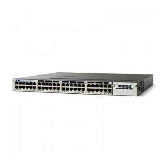
Page 2: Box Contents
14 (Optional) StackPower cable (0.305-meter or 1.5-meter) 1. Catalyst WS-C3750X-48 switch shown. Your switch model might look different. 2. Item is orderable. Verify that you have received these items. If any item is missing or damaged, contact your Cisco Note representative or reseller for instructions. -
Page 3: Running Express Setup
Running Express Setup Running Express Setup You should use Express Setup to enter the initial IP information. This enables the switch to connect to local routers and the Internet. You can access the switch through the IP address for further configuration. - Page 4 Before going to the next step, wait until POST is complete. Note Troubleshooting: If the SYST LED blinks green, does not turn green, or turns amber, contact your Cisco representative or reseller. The switch failed the power-on self-test (POST). Step 5 Press and hold the Mode button until all the LEDs next to the Mode button turn green.
- Page 5 The other device is turned on. • Step 7 Start a browser session on the PC, and enter the IP address 10.0.0.1. When prompted, enter the default password, cisco. The switch ignores text in the username field. Note The Express Setup window appears.
- Page 6 In the Confirm Switch Password field, enter your password again. Note You must change the default password, cisco. (Optional) Enter this information in the Ethernet Management Port Settings fields: In the IP Address field, enter the IP address of the Ethernet management port. In the IP Subnet Mask field, click •...
- Page 7 Running Express Setup Step 10 (Optional) You can select the Advanced Settings tab on the Express Setup window and enter the advanced settings now or enter them later by using the device manager interface. In the Telnet Access field, click Enable if you are going to use Telnet to manage the switch by using the •...
-
Page 8: Managing The Switch
When the device manager appears, you can continue with the configuration. Managing the Switch After completing Express Setup and installing the switch in your network, you can use these options for configuration: Device Manager • Cisco Network Assistant • Command-Line Interface • Other Management Options • Device Manager The simplest way to manage the switch is by using the device manager in the switch memory. - Page 9 When you run the installer, follow the instructions. In the final panel, click Finish. Refer to the Network Assistant online help and the getting started guide for more information. Command-Line Interface You can enter Cisco IOS commands and parameters through the CLI. Use one of these options to it: USB Console Port •...
-
Page 10: Installing The Switch
SNMP-compatible workstation that is running platforms such as HP OpenView or SunNet Manager. The Cisco IE2100 Series Configuration Registrar is a network management device that works with embedded Cisco Networking Services (CNS) agents in the switch software. You can use the Registrar to automate initial configurations and configuration updates. - Page 11 Translations of these warning statements appear in the Regulatory Compliance and Safety Information for the Catalyst 3750-X and 3560-X Switch document on Cisco.com. To prevent the switch from overheating, do not operate it in an area that exceeds the maximum Warning recommended ambient temperature of 113°F (45°C).
- Page 12 Installing the Switch To comply with the Telcordia GR-1089 Network Equipment Building Systems (NEBS) standard for Caution electromagnetic compatibility and safety, connect the Ethernet cables only to intrabuilding or nonexposed wiring or cabling. The grounding architecture of this product is DC-isolated (DC-I). Note Attaching the Brackets Use three (for front-mount) or four (for mid- or rear-mount) number-8 Phillips flat-head screws to attach...
- Page 13 Installing the Switch Rack-Mount the Switch Use the four number-12 Phillips machine screws to attach the brackets to the rack. Use the black Phillips machine screw to attach the cable guide to the left or right bracket. Warning To prevent bodily injury when mounting or servicing this unit in a rack, you must take special precautions to ensure that the system remains stable.
-
Page 14: Securing The Ac Power Cord (Optional)
StackWise Cabling Configurations This illustration shows the recommended stack configuration with connections using 0.5-meter StackWise cables. For more configuration examples, see the hardware installation guide on Cisco.com. Catalyst 3750-X and 3560-X Switch Getting Started Guide OL-19590-01... -
Page 15: Connecting The Stackpower Cables (Catalyst 3750-X Switch)
STACK 1 STACK 2 Connecting the StackPower Cables (Catalyst 3750-X Switch) Always use a Cisco-approved StackPower cable to connect the switches. The Catalyst 3750-X S-PWR ports accept either the yellow or the green end of the StackPower cable. Note Align the connector and connect the StackPower cable to the S-PWR port on the switch rear panel and finger-tighten the screw. -
Page 16: Installing The Network Module (Optional)
You can configure a StackPower stack of up to four switches for either power-sharing or redundancy. This illustration shows the recommended stack configuration with connections using 0.305-meter StackPower cables. For more examples, see the hardware installation guide on Cisco.com. W R- 71 5W C3 KX -P... -
Page 17: Connecting The Switch Ports
Depending upon the installed power supply, the 10/100/1000 ports support Power over Ethernet (PoE) and PoE+. PoE inline power supports devices compliant with IEEE 802.3af, as well as prestandard Cisco IP Phones and Cisco Aironet Access Points. Each port can deliver up to 15.4 W of power. - Page 18 Connect the other cable end to the other device. Use only Cisco SFP modules with the switch. For a list of supported modules, see the release notes on Cisco.com. For detailed instructions on installing, removing, and connecting to SFP modules, see the SFP module documentation.
-
Page 19: Troubleshooting
Express Setup? LEDs are green before you press the Mode button to enter the Express Setup mode. POST errors are usually fatal. Contact your Cisco technical support representative if your switch fails POST. Did you press the Mode button while the If yes, wait until POST completes. -
Page 20: Obtaining Documentation And Submitting A Service Request
First look for a solution to your problem in the troubleshooting section of the hardware installation guide or the software configuration guide on Cisco.com. You can also access the Cisco Technical Support and Documentation website for a list of known hardware problems and extensive troubleshooting documentation. - Page 21 Catalyst 3750-X, 3750-E, 3560-X, and 3560-E Switch System Message Guide • Cisco IOS Software Installation Document • Information about Cisco SFP and SFP+ modules is available from this Cisco.com site: • http://www.cisco.com/en/US/products/hw/modules/ps5455/prod_installation_guides_list.html SFP compatibility matrix documents are available from this Cisco.com site: http://www.cisco.com/en/US/products/hw/modules/ps5455/products_device_support_tables_list.ht...
- Page 22 Obtaining Documentation and Submitting a Service Request Cisco and the Cisco logo are trademarks or registered trademarks of Cisco and/or its affiliates in the U.S. and other countries. To view a list of Cisco trademarks, go to this URL: www.cisco.com/go/trademarks. Third-party trademarks mentioned are the property of their respective owners. The use of the word partner does not imply a partnership relationship between Cisco and any other company.