Table of Contents
Advertisement
Advertisement
Table of Contents

Related Manuals for Supermicro H11DSi


Summary of Contents for Supermicro H11DSi
- Page 1 H11DS / H11DS USER’S MANUAL Revision 1.1a...
- Page 2 State of California, USA. The State of California, County of Santa Clara shall be the exclusive venue for the resolution of any such disputes. Supermicro's total liability for all claims will not exceed the price paid for the hardware product.
- Page 3 About This Manual This manual is written for system integrators, IT technicians and knowledgeable end users. It provides information for the installation and use of the H11DSi / H11DSi-NT motherboard. About This Motherboard Built upon the functionality and capability of the EPYC 7001/7002* Series Processors , the H11DSi / H11DSi-NT motherboard provides superior graphics capability and system performance while consuming little power.
- Page 4 H11DSi / H11DSi-NT User's Manual Contacting Supermicro Headquarters Address: Super Micro Computer, Inc. 980 Rock Ave. San Jose, CA 95131 U.S.A. Tel: +1 (408) 503-8000 Fax: +1 (408) 503-8008 Email: marketing@supermicro.com (General Information) support@supermicro.com (Technical Support) Website: www.supermicro.com Europe Address: Super Micro Computer B.V.
-
Page 5: Table Of Contents
Preface Table of Contents Chapter 1 Introduction Quick Reference .......................11 Quick Reference Table ......................12 Motherboard Features .......................14 1.2 Processor and Chipset Overview ..................17 1.3 Special Features ........................17 Recovery from AC Power Loss ..................17 1.4 System Health Monitoring ....................18 Onboard Voltage Monitors ....................18 Fan Status Monitor with Firmware Control ...............18 Environmental Temperature Control .................18 System Resource Alert......................18... - Page 6 H11DSi / H11DSi-NT User's Manual Power Connections ......................40 Headers ..........................41 2.8 Jumper Settings .........................44 How Jumpers Work ......................44 2.9 LED Indicators ........................47 Chapter 3 Troubleshooting 3.1 Troubleshooting Procedures ....................49 Before Power On ......................49 No Power ..........................49 No Video ...........................50 System Boot Failure ......................50 Memory Errors ........................50...
- Page 7 Preface Chapter 5 BIOS (EPYC 7002 Series) 5.1 Introduction .........................87 Starting the Setup Utility ....................87 5.2 Main Setup .........................88 5.3 Advanced ..........................90 5.4 IPMI ..........................107 5.5 Event Logs ........................110 5.6 Security ..........................112 5.7 Boot ..........................115 5.8 Save & Exit ........................117 Appendix A Software Installation A.1 Installing Software Programs ...................119 A.2 SuperDoctor...
-
Page 8: Chapter 1 Introduction
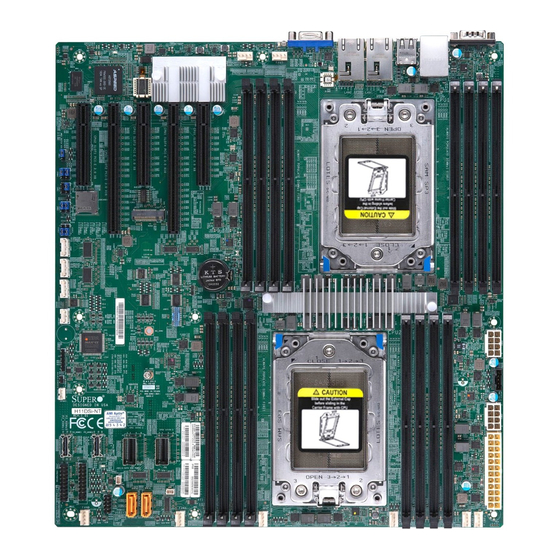
• Product safety info: http://www.supermicro.com/about/policies/safety_information.cfm • If you have any questions, please contact our support team at: support@supermicro.com This manual may be periodically updated without notice. Please check the Supermicro website for possible updates to the manual revision level. - Page 9 Chapter 1: Introduction Figure 1-1. H11DSi / H11DSi-NT Motherboard Image Note: All graphics shown in this manual were based upon the latest PCB revision available at the time of publication of the manual. The motherboard you received may or may not look...
- Page 10 H11DSi / H11DSi-NT User's Manual Figure 1-2. H11DSi / H11DSi-NT Motherboard Layout JCOM1 LED1 COM1 FAN6 LAN2 LAN1 LEDM1 FAN5 IPMI_LAN USB4/5(3.0) CPU1 JSDCARD1 CMOS CLEAR JBT1 JBT1: CPU2 JSTBY1 DESIGNED IN USA H11DSi REV:1.01 BIOS LICENSE P2_NVME1 CPU1 SATA0-3...
-
Page 11: Quick Reference
CLEAR JBT1 JBT1: JIPMB1 P2-DIMME1 P2-DIMMF1 CPU2 JPWR2 P2-DIMMG1 P2-DIMMH1 CPU1-SATA0-3 JPI2C1 CPU2-SATA0-3 JSTBY1 JSTBY1 DESIGNED IN USA JPWR3 H11DSi CPU2 REV:1.01 BIOS LICENSE P2-DIMMA1 P2_NVME1 CPU1 SATA0-3 P2_NVME0 CPU2 SATA0-3 P2-DIMMB1 P2_NVME1 P2-DIMMC1 P2_NVME0 P2-DIMMD1 LED2 JTPM1 LED2 JPWR1... -
Page 12: Quick Reference Table
Back Panel USB Type A Ports for USB0/USB1 (2.0) and USB4/USB5 (3.0) USB2/3 Front Panel USB Header for USB2/USB3 (2.0). P2-NVME0/1 Processor 2 NVMe Ports 0/1 for NVMe Hard Disk Drives (H11DSi-NT only) JSTBY1 Stand-by Power Header On-board CMOS Backup Battery... - Page 13 Chapter 1: Introduction Connector Description Legacy VGA video port JSDCARD1 Micro SD Card Slot P1-DIMMA1~P1-DIMMH1 DIMM sockets for CPU1 P2-DIMMA1~P2-DIMMH1 DIMM sockets for CPU2 CPU2 SLOT 1 X8 PCIE 3.0 Slot via CPU2 CPU1 SLOT 2, SLOT 4 X16 PCIE 3.0 Slot via CPU1 CPU1 SLOT 3, SLOT 5 X8 PCIE 3.0 Slot via CPU1 Note: Jumpers, connectors, switches, and LED indicators that are not described in the...
-
Page 14: Motherboard Features
M.2 Interface: 1 SATA/PCI-E 3.0 x2 M.2 Form Factor: 2280, 22110 M.2 Key: M-Key Network • Dual RJ45 LAN Ports (H11DSi-NT: Intel X550-BT2 / (H11DSi: I350-BT2) • ATEN IPMI from ASPEED AST 2500 BMC for gigabit RJ45 port Graphics •... - Page 15 Chapter 1: Introduction Motherboard Features BIOS • 128Mb SPI AMI BIOS (board Rev. 1.x); 256Mb SPI AMI BIOS (board Rev. 2.x) • ACPI 6.1, SMBIOS 3.1.1, Plug-and-Play (PnP), RTC (Real Time Clock) wakeup, Riser Card Auto-Detection Support Power Management • ACPI power management (S5) •...
- Page 16 H11DSi / H11DSi-NT User's Manual Figure 1-3. System Block Diagram H11DSi-(NT) SYSTEM BLOCK DIAGRAM P0_DIMMA P0_DIMME P1_DIMMA P1_DIMME P0_DIMMB P0_DIMMF P1_DIMMB P1_DIMMF P0_DIMMC P0_DIMMG P1_DIMMC P1_DIMMG P0_DIMMD P0_DIMMH P1_DIMMD P1_DIMMH 2666MHz 2666MHz 2666MHz 2666MHz SVID CPU1 SVID CPU2 5 Phase VR...
-
Page 17: Processor And Chipset Overview
• System Management Bus (SMBus) Specification Version 3.1.1 1.3 Special Features This section describes the health monitoring features of the H11DSi / H11DSi-NT motherboard. The motherboard has an onboard System Hardware Monitor chip that supports system health monitoring. Recovery from AC Power Loss The Basic I/O System (BIOS) provides a setting that determines how the system will respond when AC power is lost and then restored to the system. -
Page 18: System Health Monitoring
H11DSi / H11DSi-NT User's Manual 1.4 System Health Monitoring This section describes the health monitoring features of the H11DSi / H11DSi-NT motherboard. The motherboard has an onboard chip that supports system health monitoring. Once a voltage becomes unstable, a warning is given or an error message is sent to the screen. The user can adjust the voltage thresholds to define the sensitivity of the voltage monitor. -
Page 19: Acpi Features
Chapter 1: Introduction 1.5 ACPI Features ACPI stands for Advanced Configuration and Power Interface. The ACPI specification defines a flexible and abstract hardware interface that provides a standard way to integrate power management features throughout a computer system including its hardware, operating system and application software. -
Page 20: Chapter 2 Installation
H11DSi / H11DSi-NT User's Manual Chapter 2 Installation 2.1 Static-Sensitive Devices Electrostatic Discharge (ESD) can damage electronic com ponents. To prevent damage to your motherboard, it is important to handle it very carefully. The following measures are generally sufficient to protect your equipment from ESD. -
Page 21: Motherboard Installation
Chapter 2: Installation 2.2 Motherboard Installation All motherboards have standard mounting holes to fit different types of chassis. Make sure that the locations of all the mounting holes for both the motherboard and the chassis match. Although a chassis may have both plastic and metal mounting fasteners, metal ones are highly recommended because they ground the motherboard to the chassis. - Page 22 H11DSi / H11DSi-NT User's Manual Figure 2-1. Motherboard Mounting Holes...
-
Page 23: Installing The Motherboard
Chapter 2: Installation Installing the Motherboard 1. Install the I/O shield into the back of the chassis. 2. Locate the mounting holes on the motherboard. See the previous page for the locations. 3. Locate the matching mounting holes on the chassis. Align the mounting holes on the motherboard with the mounting holes on the chassis. -
Page 24: Processor And Heatsink Installation
CPU socket cap is in place and none of the socket pins are bent; otherwise, contact your retailer immediately. • Refer to the Supermicro website for updates on CPU support. Installing the Processor and Heatsink 1. Unscrew the screws holding down Force Frame in the sequence of 3-2-1. The screws are numbered on the Force Frame next to each screw hole. - Page 25 Chapter 2: Installation 2. The spring-loaded Force Frame will raise up after the last screw securing it (#1) is removed. Gently allow it to lift up to its stopping position. 3. Lift the Rail Frame up by gripping the lift tabs near the front end of the rail frame. While keeping a secure grip of the Rail Frame, lift it to a position so you can do the next step of removing the External Cap.
- Page 26 H11DSi / H11DSi-NT User's Manual 4. Remove the External Cap from the Rail Frame by pulling it upwards through the rail guides on the Rail Frame. External Cap PnP Cover Cap 5. The CPU Package is shipped from the factory with the blue Carrier Frame pre- assembled.
- Page 27 Chapter 2: Installation Note: You can only install the CPU inside the socket in one direction with the handle at the top. Make sure that it is properly inserted into the CPU socket before closing the Rail Frame plate. If it doesn't close properly, do not force it as it may damage your CPU. Instead, open the Rail Frame plate again, and double-check that the CPU is aligned properly.
- Page 28 H11DSi / H11DSi-NT User's Manual 9. Gently lower the Force Frame down onto the Rail Frame and hold it in place until it is seated in the Socket housing. Note that the Force Frame is spring loaded and has to be held in place before it is secured.
- Page 29 Chapter 2: Installation 11. After the Force Frame is secured and the CPU package is in place, now you must install the heatsink to the frame. Lower the heatsink down till it rests securely over the four screw holes on CPU Package on the socket frame. 12.
- Page 30 H11DSi / H11DSi-NT User's Manual Un-installing the Processor and Heatsink 1. Remove the heatsink attached to the top of the CPU Package by reversing the installation procedure. 2. Clean the Thermal grease left by the heatsink on the CPU package lid to limit the risk of it contaminating the CPU package land pads or contacts in the socket housing.
-
Page 31: Memory Support And Installation
Memory Support The H11DSi / H11DSi-NT supports 2 TB of ECC DDR4 2666 MHz speed / 4TB of ECC DDR4 3200 MHz speed (Board reversion 2.x required), RDIMM/LRDIMM/3DS/NVDIMM memory in 16 slots. Refer to the table below for additional memory information. - Page 32 H11DSi / H11DSi-NT User's Manual DIMM Population Guide (AMD 7002 Processor) CPU# Channel 1 DIMM (Supported, but not recommended) CPU1 2 DIMMS (Supported, but not recommended) CPU1 4 DIMMS (Conditionally recommended if 32 cores or fewer) CPU1 ...
-
Page 33: Dimm Module Population
P1-DIMMA1 P1-DIMMB1 JSDCARD1 P1-DIMMC1 P1-DIMMD1 CMOS CLEAR JBT1 JBT1: P2-DIMME1 P2-DIMMF1 CPU2 P2-DIMMG1 P2-DIMMH1 JSTBY1 DESIGNED IN USA H11DSi REV:1.01 BIOS LICENSE P2-DIMMA1 P2_NVME1 CPU1 SATA0-3 P2_NVME0 CPU2 SATA0-3 P2-DIMMB1 P2-DIMMC1 P2-DIMMD1 LED2 JSD1 JSD1/2:SATA DOM POWER JSD2 MH10 FANB... -
Page 34: Dimm Installation
H11DSi / H11DSi-NT User's Manual DIMM Installation 1. Insert the desired number of DIMMs into the memory slots, there is no specific sequence or order required Receptive 2. Push the release tab outwards on one Point end of the DIMM slot to unlock it. -
Page 35: Rear I/O Ports
FAN6 LAN2 LAN1 LEDM1 FAN5 IPMI_LAN USB4/5(3.0) CPU1 JSDCARD1 CMOS CLEAR JBT1 JBT1: CPU2 JSTBY1 DESIGNED IN USA H11DSi REV:1.01 BIOS LICENSE P2_NVME1 P2_NVME0 CPU1 SATA0-3 CPU2 SATA0-3 LED2 JSD1 JSD1/2:SATA DOM POWER JSD2 MH10 FANB FANA USB2/3 P2-SATA0 SATA DOM+POWER FAN4 Figure 2-1. - Page 36 H11DSi / H11DSi-NT User's Manual Universal Serial Bus (USB) Ports There are two USB 2.0 ports (USB0/1) and two USB 3.0 ports (USB4/5) on the I/O back panel. LAN Port#1, LAN Port#2 Two LAN ports are located on the I/O back panel. These ports accept an RJ45 type cable.
-
Page 37: Front Control Panel
JF1 contains header pins for various buttons and indicators that are normally located on a control panel at the front of the chassis. These connectors are designed specifically for use with Supermicro chassis. See the figure below for the descriptions of the front control panel buttons and LED indicators. - Page 38 H11DSi / H11DSi-NT User's Manual Power Button The Power Button connection is located on pins 1 and 2 of JF1. Momentarily contacting both pins will power on/off the system. This button can also be configured to function as a suspend button (with a setting in the BIOS - see Chapter 4).
- Page 39 The NIC (Network Interface Controller) LED connection for LAN port 1 is located on pins 11 and 12 of JF1, and the LED connection for LAN Port 2 is on Pins 9 and 10. Attach the NIC LED cables here to display network activity . Note: The H11DSi-NT supports 10Gb. LAN1/LAN2 LED...
-
Page 40: Connectors
H11DSi / H11DSi-NT User's Manual Power LED The Power LED connection is located on pins 15 and 16 of JF1. Power LED Pin Definitions (JF1) Pin# Definition 3.3V Power LED NMI Button The non-maskable interrupt button header is located on pins 19 and 20 of JF1. -
Page 41: Headers
Ground SATA Ports The H11DSi / H11DSi-NT has eight (8) available SATA 3.0 ports (CPU1-SATA0~3, CPU2- SATA0~3) on two iPASS connectors that are supported by CPU1 and CPU2. These use an iPASS breakout cable to support 4 ports per connector. There are also two (2) SATA ports (P2-SATA0, P2-SATA1) that are supported by CPU2 and also provides integrated DOM (Disc On Module) power. - Page 42 It enables the motherboard to deny access if the TPM associated with the hard drive is not installed in the system. Please go to the following link for more information on TPM: http://www.supermicro.com/ manuals/other/TPM.pdf. Trusted Platform Module Header...
- Page 43 Chapter 2: Installation USB 2/3 The USB 2/3 header contains a header for USB ports #2 and #3. If the chassis supports this feature, connect the Front Panel cable to this header to access USB ports #2 and #3 directly from the chassis front panel. Front Panel USB 2.0 Header Pin Definitions Pin#...
-
Page 44: Jumper Settings
H11DSi / H11DSi-NT User's Manual 2.8 Jumper Settings How Jumpers Work To modify the operation of the motherboard, jumpers can be used to choose between optional settings. Jumpers create shorts between two pins to change the function of the connector. - Page 45 Chapter 2: Installation VGA Enable/Disable JPG1 allows you to enable or disable the VGA port. The default position is on pins 1 and 2 to enable VGA. See the table below for jumper settings. VGA Enable/Disable Jumper Settings (JPG1) Jumper Setting Definition Pins 1-2 Enabled...
- Page 46 H11DSi / H11DSi-NT User's Manual LAN Enable/Disable Jumper JPL1 will enable or disable the LAN ports on the motherboard. See the table below for jumper settings. The default setting is enabled. GLAN Enable Jumper Settings Pin# Definition Enabled (default) Disabled...
-
Page 47: Led Indicators
Chapter 2: Installation 2.9 LED Indicators LAN Port LEDs The IPMI Ethernet port has two LED indicators. The Activity LED is yellow and indicates connection and activity. The Link LED may be green, amber, or off to indicate the speed of the connection. - Page 48 H11DSi / H11DSi-NT User's Manual BMC Hearbeat LED A BMC Heartbeat LED is located at LEDM1 on the motherboard. When LEDM1 is blinking, the BMC is functioning normally. See the table below for more information. BMC Heartbeat LED State LED Color...
-
Page 49: Chapter 3 Troubleshooting
Chapter 3: Troubleshooting Chapter 3 Troubleshooting 3.1 Troubleshooting Procedures Use the following procedures to troubleshoot your system. If you have followed all of the procedures below and still need assistance, refer to the ‘Technical Support Procedures’ and/ or ‘Returning Merchandise for Service’ section(s) in this chapter. Always disconnect the AC power cord before adding, changing or installing any non hot-swap hardware components. -
Page 50: No Video
H11DSi / H11DSi-NT User's Manual No Video 1. Check that the VGA cable is connected properly, and the monitor is on. 2. Set JPG1 to [1-2] and check if you follow the guidelines to install the memory module (see DIMM Module Population in chapter 2). -
Page 51: When The System Becomes Unstable
2. Memory support: Make sure that the memory modules are supported by testing the modules using memtest86 or a similar utility. Note: Refer to the product page on our website at http:\\www.supermicro.com for memory and CPU support and updates. 3. HDD support: Make sure that all hard disk drives (HDDs) work properly. Replace the bad HDDs with good ones. -
Page 52: Technical Support Procedures
3.3 Frequently Asked Questions Question: What type of memory does my motherboard support? Answer: The H11DSi / H11DSi-NT motherboard supports up to 2 TB of ECC DDR4 2400/2666 MHz speed, RDIMM/LRDIMM/3DS/NVDIMM memory in sixteen (16) slots. See Section 2.4 for details on installing memory. - Page 53 Chapter 3: Troubleshooting file to your computer. Also, check the current BIOS revision to make sure that it is newer than your BIOS before downloading. You can choose from the zip file and the .exe file. If you choose the zip BIOS file, please unzip the BIOS file onto a bootable USB device. Run the batch file using the format FLASH.BAT filename.rom from your bootable USB device to flash the BIOS.
- Page 54 H11DSi / H11DSi-NT User's Manual Question: Why did the system freeze and fail to begin installation when I tried to install Windows Server 2016? Answer: Windows Sever 2016 support is limited to less than 255 logical processors, and it does not support x2APIC. Follow the steps to solve the problem.
-
Page 55: Returning Merchandise For Service
Shipping and handling charges will be applied for all orders that must be mailed when service is complete. For faster service, RMA authorizations may be requested online (http://www.supermicro.com/ support/rma/). This warranty only covers normal consumer use and does not cover damages incurred in shipping or from failure due to the alteration, misuse, abuse or improper maintenance of products. -
Page 56: Battery Removal And Installation
H11DSi / H11DSi-NT User's Manual 3.5 Battery Removal and Installation Battery Removal To remove the onboard battery, follow the steps below: 1. Power off your system and unplug your power cable. 2. Locate the onboard battery as shown below. 3. Using a tool such as a pen or a small screwdriver, push the battery lock outwards to unlock it. -
Page 57: Chapter 4 Bios (Epyc 7001 Series)
(EPYC 7001 Series) 4.1 Introduction This chapter describes the AMIBIOS™ Setup utility for the H11DSi / H11DSi-NT motherboard. The BIOS is stored on a chip and can be easily upgraded using a flash program. Note: Due to periodic changes to the BIOS, some settings may have been added or deleted and might not yet be recorded in this manual. -
Page 58: Main Setup
H11DSi / H11DSi-NT User's Manual 4.2 Main Setup When you first enter the AMI BIOS setup utility, you will enter the Main setup screen. You can always return to the Main setup screen by selecting the Main tab on the top of the screen. The Main BIOS setup screen is shown below. - Page 59 Chapter 4: BIOS (EPYC 7001 Series) CPLD Version This item displays the version of the CPLD firmware used in the system. Memory Information Total Memory This item displays the total size of memory available in the system.
-
Page 60: Advanced
H11DSi / H11DSi-NT User's Manual 4.3 Advanced Use the arrow keys to select Boot Setup and press <Enter> to access the submenu items. Warning: Take caution when changing the Advanced settings. An incorrect value, a very high DRAM frequency, or an incorrect DRAM timing setting may make the system unstable. - Page 61 Chapter 4: BIOS (EPYC 7001 Series) Bootup NumLock State Use this feature to set the Power on state for the <Numlock> key. The options are Off and On. Wait For "F1" If Error Use this feature to force the system to wait until the 'F1' key is pressed if an error occurs. The options are Disabled and Enabled.
- Page 62 H11DSi / H11DSi-NT User's Manual PSP Firmware Versions This section displays the Platform Security Processor (PSP) firmware versions. PSP Directory Level 1 (Fixed) • PSP Recovery BL Ver • SMU FW Version • ABL Version • APCB Version • APOB Version •...
- Page 63 Chapter 4: BIOS (EPYC 7001 Series) CPU Configuration SMT Mode Use this setting to specify Simultaneous Multithreading. Options include Off for 1T single thread and Auto for 2T two-thread if your system is capable of it. Core Performance Boost This setting is used to configure for Core Performance Boost.
- Page 64 H11DSi / H11DSi-NT User's Manual • L1 Data Cache (Size/Method) • L2 Data Cache (Size/Method) • L3 Cache per Scoket (Size/Method) NB Configuration Determinism Slider Use this setting to configure the Determinism Slider. Options include Auto, Power and Performance.
- Page 65 Chapter 4: BIOS (EPYC 7001 Series) CPU1/CPU2 Memory Information These sections are for informational purposes. They will display some details about the detected memory according to each CPU on the motherboard, such as: • Detected Size (per slot, in MB) •...
- Page 66 H11DSi / H11DSi-NT User's Manual Change Settings This feature specifies the base I/O port address and the Interrupt Request address of a serial port specified by the user. Select Auto to allow the BIOS to automatically assign the base I/O and IRQ address. The options are Auto, (IO=2F8h; IRQ=3;); (IO=3F8h; IRQ=3, 4, 5, 6, 7, 9, 10, 11, 12;);...
- Page 67 Chapter 4: BIOS (EPYC 7001 Series) as a parity bit to be sent along with the data bits. Select Space to add a Space as a parity bit to be sent with your data bits. The options are None, Even, Odd, Mark, and Space. Stop Bits A stop bit indicates the end of a serial data packet.
- Page 68 H11DSi / H11DSi-NT User's Manual and function key support. Select ANSI to use the Extended ASCII Character Set. Select VT-UTF8 to use UTF8 encoding to map Unicode characters into one or more bytes. The options are VT100, VT100+, VT-UTF8, and ANSI.
- Page 69 Chapter 4: BIOS (EPYC 7001 Series) Putty KeyPad This feature selects the settings for Function Keys and KeyPad used for Putty, which is a terminal emulator designed for the Windows OS. The options are VT100, LINUX, XTERMR6, SC0, ESCN, and VT400. Legacy Console Redirection Legacy Console Redirection Settings Redirection COM Port...
- Page 70 H11DSi / H11DSi-NT User's Manual UTF8 encoding to map Unicode characters into one or more bytes. The options are VT100, VT100+, VT-UTF8, and ANSI. Bits per Second This item sets the transmission speed for a serial port used in Console Redirection. Make sure that the same speed is used in the host computer and the client computer.
- Page 71 Chapter 4: BIOS (EPYC 7001 Series) advertised by the UPstream component in its training sequences. When Auto is selected, the HW initialized data will be used. VGA Priority Use this setting to select between onboard or offboard VGA support The options are Onboard and Offboard NVMe Firmware Source Use this setting to select between the AMI Native firmware support or the device vendor-...
- Page 72 H11DSi / H11DSi-NT User's Manual Use this setting to select which firmware function is to be loaded for onboard LAN1 on the system. Options include Disabled, PXE and iSCSI. Onboard LAN2 Option ROM Use this setting to select which firmware function is to be loaded for onboard LAN2 on the system.
- Page 73 Chapter 4: BIOS (EPYC 7001 Series) Network Stack Configuration Network Stack This setting allows you to Enable or Disable the UEFI Network Stack. Ipv4 PXE Support This setting allows you to Enable or Disable IPv4 PXE boot support. If disabled, IPv4 PXE boot support will not be available.
- Page 74 H11DSi / H11DSi-NT User's Manual SATA Information This section displays information on the detected SATA devices: • CPU1 SATA0 ~ CPU1 SATA7 iSCSI Configuration iSCSI Initiator Name This feature allows the user to enter the unique name of the iSCSI Initiator in IQN format.
-
Page 75: Ipmi
Chapter 4: BIOS (EPYC 7001 Series) 4.4 IPMI This tab allows you to configure the following IPMI settings for the system. Use this feature to configure Intelligent Platform Management Interface (IPMI) settings. BMC Firmware Revision This item indicates the IPMI firmware revision used in your system. IPMI Status (Baseboard Management Controller) This item indicates the status of the IPMI firmware installed in your system. - Page 76 H11DSi / H11DSi-NT User's Manual Erasing Settings Erase SEL Select Yes, On next reset to erase all system event logs upon next system reboot. Select Yes, On every reset to erase all system event logs upon each system reboot. Select No to keep all system event logs after each system reboot.
- Page 77 Chapter 4: BIOS (EPYC 7001 Series) Station IP Address This item displays the Station IP address for this computer. This should be in decimal and in dotted quad form. Subnet Mask This item displays the sub-network that this computer belongs to. The value of each three- digit number separated by dots should not exceed 255.
-
Page 78: Event Logs
H11DSi / H11DSi-NT User's Manual 4.5 Event Logs This tab allows the user to configure the following event logs settings for the system. Change SMBIOS Event Log Settings This feature allows the user to configure SMBIOS Event settings. Enabling/Disabling Options... - Page 79 Chapter 4: BIOS (EPYC 7001 Series) When Log is Full Select Erase Immediately to immediately erase all errors in the SMBIOS event log when the event log is full. Select Do Nothing for the system to do nothing when the SMBIOS event log is full.
-
Page 80: Security
H11DSi / H11DSi-NT User's Manual 4.6 Security This tab allows you to configure the following security settings for the system. Administrator Password Press Enter to create a new, or change an existing Administrator password. Note that if the Administrator Password is erased, the User Password will be cleared as well. - Page 81 Chapter 4: BIOS (EPYC 7001 Series) Secure Boot This option allows you specify when the Platform Key (PK) is enrolled. When enabled, the System Mode is user deployed, and the CSM function is disabled. Options include Enabled and Disabled. Secure Boot Mode Use this item to select the secure boot mode.
- Page 82 H11DSi / H11DSi-NT User's Manual Append Key Select Yes to add the KEK from the manufacturer's defaults list to the existing KEK. Select No to load the KEK from a file. The options are Yes and No. Authorized Signatures Set New Key Select Yes to load the database from the manufacturer's defaults.
-
Page 83: Boot
Chapter 4: BIOS (EPYC 7001 Series) 4.7 Boot Use this tab to configure Boot Settings: Boot Mode Select Use this item to select the type of device that the system is going to boot from. The options are LEGACY, UEFI, and DUAL. The default setting is DUAL. Legacy to EFI Support This option Enables or Disables the system to boot to an EFI OS after the boot failed from the legacy boot order. - Page 84 H11DSi / H11DSi-NT User's Manual UEFI Application Boot Priorities This feature allows the user to specify which UEFI devices are boot devices. • UEFI Boot Order #1 Hard Disk Drive BBS Priorities This feature allows the user to specify which hard disk drive devices are boot devices.
-
Page 85: Save & Exit
Chapter 4: BIOS (EPYC 7001 Series) 4.8 Save & Exit Select the Save & Exit tab to enter the Save & Exit BIOS Setup screen. Discard Changes and Exit Select this option to quit the BIOS Setup without making any permanent changes to the system configuration, and reboot the computer. - Page 86 H11DSi / H11DSi-NT User's Manual Default Options Restore Defaults To set this feature, select Restore Defaults from the Save & Exit menu and press <Enter>. These are factory settings designed for maximum system stability, but not for maximum performance. Save as User Defaults To set this feature, select Save as User Defaults from the Exit menu and press <Enter>.
-
Page 87: Chapter 5 Bios (Epyc 7002 Series)
(EPYC 7002 Series) 5.1 Introduction This chapter describes the AMIBIOS™ Setup utility for the H11DSi / H11DSi-NT motherboard. The BIOS is stored on a chip and can be easily upgraded using a flash program. Note: Due to periodic changes to the BIOS, some settings may have been added or deleted and might not yet be recorded in this manual. -
Page 88: Main Setup
H11DSi / H11DSi-NT User's Manual 5.2 Main Setup When you first enter the AMI BIOS setup utility, you will enter the Main setup screen. You can always return to the Main setup screen by selecting the Main tab on the top of the screen. The Main BIOS setup screen is shown below. - Page 89 Chapter 5: BIOS (EPYC 7002 Series) Build Date This item displays the date when the version of the BIOS firmware used in the system was built. CPLD Version This item displays the version of the CPLD firmware used in the system. Memory Information Total Memory This item displays the total size of memory available in the system.
-
Page 90: Advanced
H11DSi / H11DSi-NT User's Manual 5.3 Advanced Use the arrow keys to select a top item and press <Enter> to access the submenu items. Warning: Take caution when changing the Advanced settings. An incorrect value, a very high DRAM frequency, or an incorrect DRAM timing setting may make the system unstable. - Page 91 Chapter 5: BIOS (EPYC 7002 Series) Bootup NumLock State Use this feature to set the Power on state for the <Numlock> key. The options are On and Off. Wait For "F1" If Error Use this feature to force the system to wait until the 'F1' key is pressed if an error occurs. The options are Disabled and Enabled.
- Page 92 H11DSi / H11DSi-NT User's Manual PSP Firmware Versions This section displays the Platform Security Processor (PSP) firmware versions. PSP Directory Level 1 (Fixed) • PSP Recovery BL Ver • SMU FW Version • ABL Version PSP Directory Level 2 (Updateable) •...
- Page 93 Chapter 5: BIOS (EPYC 7002 Series) Serial Port 1 Configuration Serial Port Select The options are Disabled and Enabled. Device Settings This item displays the status of a serial part specified by the user. Change Settings This feature specifies the base I/O port address and the Interrupt Request address of a serial port specified by the user.
- Page 94 H11DSi / H11DSi-NT User's Manual Bits per second Use this feature to set the transmission speed for a serial port used in Console Redirection. Make sure that the same speed is used in the host computer and the client computer. A lower transmission speed may be required for long and busy lines.
- Page 95 Chapter 5: BIOS (EPYC 7002 Series) Console Redirection Select Enabled to enable SOL console redirection support for a serial port specified by the user. The options are Disabled and Enabled. *If the item above set to Enabled, the following items will become available for user's configuration: Console Redirection Settings Terminal Type...
- Page 96 H11DSi / H11DSi-NT User's Manual is full. Send a "Start" signal to start sending data when the receiving buffer is empty. The options are None and Hardware RTS/CTS. VT-UTFB Combo Key Support Select Enabled to enable VT-UTF8 Combination Key support for ANSI/VT100 terminals.
- Page 97 Chapter 5: BIOS (EPYC 7002 Series) *If the item above set to Enabled, the following items will become available for user's configuration: Console Redirection Settings Out-of-Band Mgmt Port The feature selects a serial port in a client server to be used by the Microsoft Windows Emergency Management Services (EMS) to communicate with a remote host server.
- Page 98 H11DSi / H11DSi-NT User's Manual Stop Bits A stop bit indicates the end of a serial data packet. Select 1 Stop Bit for standard serial data communication. Select 2 Stop Bits if slower devices are used. The options are 1 and 2.
- Page 99 Chapter 5: BIOS (EPYC 7002 Series) • Processor Family • Processor Model • Microcode Patch Level • L1 Instruction Cache (Size/Method) • L1 Data Cache (Size/Method) • L2 Cache (Size/Method) • L3 Cache per Scoket (Size/Method) CPU2 Information These sections are for informational purposes. They will display some details about the detected CPUs on the motherboard, such as: •...
- Page 100 H11DSi / H11DSi-NT User's Manual IOMMU Use this setting to enable/disable IOMMU. Options include Disabled, Enabled, and Auto. ACS Enable Use this setting to enable/disable ACS. Options include Enabled, Disabled and Auto. Package Power Limit Control Use this setting for Package Power Limit Control. Options include Manual and Auto.
- Page 101 Chapter 5: BIOS (EPYC 7002 Series) DRAM Scrub Time This setting provides a value that is the number of hours to scrub memory. The options are Disabled, 1 hour, 4 hours, 8 hours, 16 hours, 24 hours, 48 hours and Auto. CPU1 Memory Information These sections are for informational purposes.
- Page 102 H11DSi / H11DSi-NT User's Manual VGA Priority Use this setting to select between onboard or offboard VGA support The options are Onboard and Offboard NVMe Firmware Source Use this setting to select between the AMI Native firmware support or the device vendor- defined firmware support.
- Page 103 Chapter 5: BIOS (EPYC 7002 Series) Onboard LAN2 Option ROM Use this setting to select which firmware function is to be loaded for onboard LAN2 on the system. Options include Disabled, PXE and iSCSI. P2_NVMe0 OpROM Use this setting to select which firmware function is to be loaded for P2_NVMe0 OpROM on the system.
- Page 104 H11DSi / H11DSi-NT User's Manual IPv4 PXE Support This setting allows you to enable or disable IPv4 PXE boot support. If disabled, IPv4 PXE boot support will not be available. The options are Disabled and Enabled. IPv4 HTTP Support This setting allows you to enable or disable IPv4 HTTP boot support. If disabled, IPv4 HTTP boot support will not be available.
- Page 105 Chapter 5: BIOS (EPYC 7002 Series) Port 60/64 Emulation Select Enabled for I/O port 60h/64h emulation support, which in turn, will provide complete legacy USB keyboard support for the operating systems that do not support legacy USB devices. The options include Disabled and Enabled. SATA Configuration This section displays the detected SATA devices installed on the system.
- Page 106 H11DSi / H11DSi-NT User's Manual iSCSI Configuration iSCSI Initiator Name This feature allows the user to enter the unique name of the iSCSI Initiator in IQN format. Once the name of the iSCSI Initiator is entered into the system, configure the proper settings for the following items.
-
Page 107: Ipmi
Chapter 5: BIOS (EPYC 7002 Series) 5.4 IPMI This tab allows you to configure the following IPMI settings for the system. Use this feature to configure Intelligent Platform Management Interface (IPMI) settings. BMC Firmware Revision This item indicates the IPMI firmware revision used in your system. IPMI Status (Baseboard Management Controller) This item indicates the status of the IPMI firmware installed in your system. - Page 108 H11DSi / H11DSi-NT User's Manual Erasing Settings Erase SEL Select Yes, On next reset to erase all system event logs upon next system reboot. Select Yes, On every reset to erase all system event logs upon each system reboot. Select No to keep all system event logs after each system reboot.
- Page 109 Chapter 5: BIOS (EPYC 7002 Series) Station IP Address This item displays the Station IP address for this computer. This should be in decimal and in dotted quad form. Subnet Mask This item displays the sub-network that this computer belongs to. The value of each three- digit number separated by dots should not exceed 255.
-
Page 110: Event Logs
H11DSi / H11DSi-NT User's Manual 5.5 Event Logs This tab allows the user to configure the following event logs settings for the system. Change SMBIOS Event Log Settings This feature allows the user to configure SMBIOS Event settings. Enabling/Disabling Options... - Page 111 Chapter 5: BIOS (EPYC 7002 Series) When Log is Full Select Erase Immediately to immediately erase all errors in the SMBIOS event log when the event log is full. Select Do Nothing for the system to do nothing when the SMBIOS event log is full.
-
Page 112: Security
H11DSi / H11DSi-NT User's Manual 5.6 Security This tab allows you to configure the following security settings for the system. Administrator Password Press Enter to create a new, or change an existing Administrator password. Note that if the Administrator Password is erased, the User Password will be cleared as well. - Page 113 Chapter 5: BIOS (EPYC 7002 Series) Secure Boot This option allows you specify when the Platform Key (PK) is enrolled. When enabled, the System Mode is user deployed, and the CSM function is disabled. Options include Disabled and Enabled . Secure Boot Mode Use this item to select the secure boot mode.
- Page 114 H11DSi / H11DSi-NT User's Manual Append Select Yes to add the KEK from the manufacturer's defaults list to the existing KEK. Select No to load the KEK from a file. The options are Yes and No. Authorized Signatures Update Select Yes to load the database from the manufacturer's defaults. Select No to load the DB from a file.
-
Page 115: Boot
Chapter 5: BIOS (EPYC 7002 Series) 5.7 Boot Use this tab to configure Boot Settings: Boot Mode Select Use this item to select the type of device that the system is going to boot from. The options are Legacy, UEFI, and Dual. The default setting is Dual. Legacy to EFI Support This option enables or disables the system to boot to an EFI OS after the boot failed from the legacy boot order. - Page 116 H11DSi / H11DSi-NT User's Manual UEFI Application Boot Priorities This feature allows the user to specify which UEFI devices are boot devices. • Boot Option #1 Hard Disk Drive BBS Priorities This feature allows the user to specify which hard disk drive devices are boot devices.
-
Page 117: Save & Exit
Chapter 5: BIOS (EPYC 7002 Series) 5.8 Save & Exit Select the Save & Exit tab to enter the Save & Exit BIOS Setup screen. Discard Changes and Exit Select this option to quit the BIOS Setup without making any permanent changes to the system configuration, and reboot the computer. - Page 118 H11DSi / H11DSi-NT User's Manual Default Options Restore Optimized Defaults To set this feature, select Restore Defaults from the Save & Exit menu and press <Enter>. These are factory settings designed for maximum system stability, but not for maximum performance.
-
Page 119: Appendix A Software Installation
Appendix A Software Installation A.1 Installing Software Programs The Supermicro FTP site contains drivers and utilities for your system at ftp://ftp.supermicro. com. Some of these must be installed, such as the chipset driver. After accessing the FTP site, go into the CDR_Images directory and locate the ISO file for your motherboard. -
Page 120: Superdoctor ® 5
SMTP services to optimize the efficiency of your operation. Note: The default Username and Password for SuperDoctor 5 is ADMIN / ADMIN. Figure A-2. SuperDoctor 5 Interface Display Screen (Health Information) Note: The SuperDoctor 5 program and user’s manual can be downloaded from the Supermicro website at http://www.supermicro.com/products/nfo/sms_sd5.cfm. -
Page 121: Appendix B Standardized Warning Statements
The following statements are industry standard warnings, provided to warn the user of situations which have the potential for bodily injury. Should you have questions or experience difficulty, contact Supermicro's Technical Support department for assistance. Only certified technicians should attempt to install or configure components. - Page 122 H11DSi / H11DSi-NT User's Manual Attention Danger d'explosion si la pile n'est pas remplacée correctement. Ne la remplacer que par une pile de type semblable ou équivalent, recommandée par le fabricant. Jeter les piles usagées conformément aux instructions du fabricant.
-
Page 123: Product Disposal
Appendix B: Warning Statements B-2 Product Disposal Warning! Ultimate disposal of this product should be handled according to all national laws and regulations. 製品の廃棄 この製品を廃棄処分する場合、 国の関係する全ての法律 ・ 条例に従い処理する必要があります。 警告 本产品的废弃处理应根据所有国家的法律和规章进行。 警告 本產品的廢棄處理應根據所有國家的法律和規章進行。 Warnung Die Entsorgung dieses Produkts sollte gemäß allen Bestimmungen und Gesetzen des Landes erfolgen. -
Page 124: Appendix C Uefi Bios Recovery
Warning: Do not upgrade the BIOS unless your system has a BIOS-related issue. Flashing the wrong BIOS can cause irreparable damage to the system. In no event shall Supermicro be liable for direct, indirect, special, incidental, or consequential damages arising from a BIOS update. - Page 125 USB flash drive with FAT16 or FAT32 format and rename the file to SUPER.ROM. Note: If you cannot locate the "SUPER.ROM" file in your driver disk, visit our website at www.supermicro.com to download the correct BIOS image into a USB flash device and rename it "SUPER.ROM".
- Page 126 SUPERMICO BIOS Update: https://www.youtube.com/watch?v=S8z6iOEHGwY * If the BIOS flash recovery fails, contact our RMA Department to have the BIOS chip reprogrammed. This will require shipping the board to Supermicro for repair. Submit your RMA request at https://www.supermicro.com/support/rma Please make sure to follow all instructions when returning the motherboard.