Table of Contents
Advertisement
Installation Instructions & Homeowner's Manual
WARNING! IF THE INFORMATION IN THIS MANUAL IS NOT FOLLOWED EXACTLY, A FIRE OR
EXPLOSION MAY RESULT CAUSING PROPERTY DAMAGE,PERSONAL INJURY OR LOSS OF LIFE.
FOR YOUR SAFETY
WHAT TO DO IF YOU SMELL GAS:
* Do not try to light any appliance.
* Do not touch any electric switch.
• Do not use any phone in your building.
* Extinguish all flames.
* Immediately call your gas supplier from
your neighbours phone. Follow the gas
suppliers instructions.
* If you cannot reach your gas supplier call the
fire department.
INSTALLER: DO NOT DISCARD THIS MANUAL - LEAVE FOR HOMEOWNER
The Vermont Castings
Majestic Products Company
475 Admiral Blvd., Mississauga
Ontario, Canada L5T 2N1
www.majesticproducts.com / www.vermontcastings.com
- 1 -
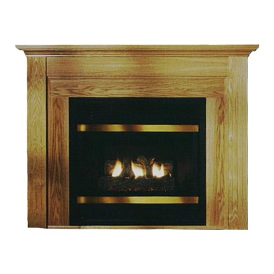
Direct Vent
Rear Vent
BHDR36
FOR YOUR SAFETY
DO NOT STORE
OR USE GASOLINE OR OTHER
FLAMMABLE VAPOURS AND LIQUIDS
IN THE VICINITY OF THIS OR ANY
OTHER APPLIANCE.
* Installation and service must be performed
by a qualified installer, service agency or
your gas supplier.
Model
10001826
11/01 Rev. 1
Advertisement
Table of Contents
Troubleshooting

Related Manuals for Vermont Castings BHDR36 RN


Summary of Contents for Vermont Castings BHDR36 RN
-
Page 1: Direct Vent
* Installation and service must be performed by a qualified installer, service agency or your gas supplier. The Vermont Castings Majestic Products Company 475 Admiral Blvd., Mississauga Ontario, Canada L5T 2N1 - 1 - Direct Vent Rear Vent Model BHDR36 10001826 11/01 Rev. 1... -
Page 2: Table Of Contents
PLEASE READ THE INSTALLATION & OPERATING INSTRUCTIONS BEFORE USING APPLIANCE. Thank you and congratulations on your purchase. IMPORTANT: R ead all instructions and warnings carefully before starting installation. instructions may result in a possible fire hazard and will void the warranty. Installation Instructions ... -
Page 3: Important
INSTALLATION INSTRUCTIONS This gas appliance should be installed by a qualified installer in accordance with local building codes and with current CAN / CGA-B149 (. 1 or .2) Installation codes for Gas Burning Appliances and Equipment. or for U.S.A Installations follow local codes and/ or the current National Fuel Gas Code. -
Page 4: Fireplace Dimensions
FIREPLACE DIMENSIONS FRAMING & FINISHING BHDR36 36" 914mm 1/4" 870mm 21" 533mm 33" 838mm 24" 610mm 16" 406mm 19" 483mm 7/8" 606mm 1/2" 698mm 3/4" 171mm 10" 254mm 1/2" 343mm 5/8" 1057mm 7/8" 1495mm 7/8" 748mm 1/2" 419mm 1/2" ROW 36 927mm 35"... -
Page 5: Mantels
MANTELS Depending on the width of the mantel it may be installed higher or lower from the top of the louvre opening. See drawing and chart below for proper installation height of your combustible mantel piece. Non-combustible mantels may be installed at any height above the appliance opening. When using paint or lacquer to finish the mantel, such paint or lacquer must be heat resistant to prevent discolouration. -
Page 6: Final Finishing
GAS SPECIFICATIONS MODEL FUEL GAS CONTROL B.T.U.H BHDR36 RN Natural Gas Millivolt Hi/Lo BHDR36 RP Propane Gas Millivolt Hi/Lo GAS INLET & MANIFOLD PRESSURES... -
Page 7: Gas Line Installation
GAS LINE INSTALLATION When purging gas line the front glass must be removed. The gas pipeline can be brought in through the right side, left side of the appliance as well as the bottom. Knockouts are provided at convenient locations to allow for the gas pipe installation and testing of any gas connection. -
Page 8: General Venting Information
GENERAL VENTING INFORMATION Your fireplace is approved to be vented either through the side wall, or vertical through the roof. Only Majestic venting components specifically approved and labelled for this fireplace may be used. Minimum clearances between vent pipes and combustible materials is one (1") inch (25 mm), except where stated otherwise. -
Page 9: Termination Clearances
Termination Clearances Termination clearances for buildings with combustible and noncombustible exteriors. Inside Corner Combustible 6"(152mm) Noncombustible 2"(50mm) Balcony - with no side wall Combustible& Non-Combustible 12"(305mm) GENERAL INFORMATION ON ASSEMBLING THE VENT PIPES WITH CRIMPED ENDS Before joining elbows and pipes apply a bead of high temperature sealant to crimped end of elbow or pipe. (Fig.12) Join pipes and secure joints with three (3) sheetmetal screws. -
Page 10: Assembling Vent Pipes With Crimped Ends
REAR VENTING APPLICATIONS Note: It is not necessary to seal the vent pipe joints for any rear vent applications. Minimum clearances between vent pipe and com- bustible materials are as follows: - 2" (50 mm) Sides - 1" (25 mm) Bottom - 1"... -
Page 11: Vertical Sidewall Installations
STEP 5 Guide the vent termination 4" collar into the 4" pipe then the 7" collar into the 7" pipe. Do not force the venting into position. If the pipes do not line up with the termination collars, disassemble elbows or pipes and reattach to the fireplace collar. -
Page 12: Vertical Sidewall Applications
VERTICAL SIDEWALL APPLICATIONS The maximum number of 90 degree elbows per side wall installation is four (4), (includes 7DVRT90 off back of unit) The maximum number of 45 degree elbows permitted per side wall installation is two (2). These elbows can be installed in either the vertical or horizontal run. -
Page 13: How To Use The Vent Graph
HOW TO USE THE VENT GRAPH 1. Determine the height of the centre of the horizontal vent pipe exiting through the outer wall. Using this dimension on the Sidewall Vent Graph (Fig. 21), locate the point it intersects with the slanted graph line. - Page 14 STEP 2 Fig. 25. Measure wall thickness and cut adjustable zero clearance sleeve parts to proper length (MAXIMUM 12"). Adjust sleeve to minimum (9-3/8" x 9-3/8") and attach to firestop with #8 sheet metal screws (supplied). Install STEP 2 firestop assembly. Zero clearance sleeve is only required for combustible walls.
-
Page 15: Below Grade Installations
BELOW GRADE INSTALLATIONS When it is not possible to meet the required vent termi- nal clearances of 12 inches (305mm) above grade level a model #7DVSKS vent kit is recommended. It allows installation depth of down to 7 inches (178mm) below grade level. -
Page 16: Vertical Through The Roof Installation
c) A minimum of an 8 ft. vertical rise. d) Two sets of 45 degree elbow offsets within these vertical installations. From 0 to a maximum of 8 ft. a vent pipe can be used between elbows. (Fig. 33) e) 7DVCS must be used to support offsets. (Fig. 34) This application will require that you first determine the roof pitch and use the appropriate 7DVSKV (A,B or F). -
Page 17: Crimped End Venting Components
CRIMPED END VENTING COMPONENTS 7DVRVT - Through the wall Rear Vent Termination Starter Kit -Model 7DVSK - Sidewall Venting Starter Kit - Model 7DVSKV - Vertical Venting for 7DVSKV-A order 1/12 to 6/12 roof pitch for 7DVSKV-B order 7/12 to 12/12 roof pitch for 7DVSKV-F order flat roof Starter Kit - Model 7DVSKS -Snorkel Kit for Below Grade Installation... -
Page 18: Assembling Twist Lock Vent Pipes
GENERAL INFORMATION ON ASSEMBLING When using CFM Majestic twist lock pipe it is not neces- sary to use silicone to seal the twist lock joints. The only areas that need silicone are the collars on the fireplace, the telescoping pipe (if used) and the horizontal termina- tion connection (when necessary). -
Page 19: Rear Wall Installations
REAR WALL INSTALLATIONS Minimum clearance between vent pipes and combustible materials in one (1") inch (25 mm) on sides and bottom and two (2") inch (50 mm) on top. STEP 1 Locate vent opening on wall. Vent Opening — Combustible Wall (240mm) "... -
Page 20: Vertical Sidewall Installations
VERTICAL SIDEWALL INSTALLATIONS Since it is very important that the venting system maintain its balance between the combustion air intake and the flue gas exhaust, certain limitations as to vent configurations apply and must be strictly adhered to. The graph showing the relationship between vertical and horizontal side wall venting will help to determine the various vent lengths allowable. -
Page 21: How To Use The Vent Graph
120" 3048mm 90" 2286mm The maximum number of elbow degrees in a system is INSERT . (This does not include transition elbow from rear vent to vertical vent.) Fig. 46. Sample: Total 84" 2134mm 1. Determine the height of the centre of the horizontal elbow=3' 2. -
Page 22: Vent Sidewall Installation
VENT SIDEWALL INSTALLATION *IMPORTANT* Minimum clearance between vent pipes and combustible materials is one (1") inch (25 mm) on bottom, sides and top. Vent Starter Kit 7TDVSK, plus Transition Elbow 7TDVRT90 must be used in Vertical Sidewall installations. pipe must be centred inside the 7" pipe coming off the 7TDVRT90 transition elbow. -
Page 23: Below Grade Installations
STEP 5 (Fig. 54) Use the appropriate length of pipe section – telescopic or fixed – and install. The 20" section of pipe which goes through the wall is packaged with the 7TDVSK kit, and can be cut to suit if necessary. Sealing vent pipe and firestop gaps with high... -
Page 24: Vertical Through The Roof Applications
DO NOT BACK FILL AROUND SNORKEL. SOIL SHOULD NOT BE LESS THAN 4" BELOW SNORKEL. FOUNDATION RECESS WATERTIGHT SEAL AROUND PIPE SHEET METAL SCREWS If the foundation is recessed, use recess brackets (not supplied) for securing lower portion of the snorkel. Fasten brackets to wall first and then secure to snorkel with self drilling #8 x 1/2 sheet metal screws. -
Page 25: Vertical Through The Roof Installation
VERTICAL THROUGH THE ROOF INSTALLATION 1. Locate your fireplace. 2. Plumb to centre of the (4") 90 (7TDVRT90) from ceiling above and mark position. 3. Cut opening equal to 9-3/8" x 9-3/8" (240 mm x 240 mm). 4. Proceed to plumb for additional openings through the roof. -
Page 26: Twist Lock Venting Components
TWIST LOCK VENTING COMPONENTS - 26 - 7DVRVT - Through the wall Rear Vent Termination Starter Kit -Model 7TDVSK - Sidewall Venting Starter Kit - Model 7TDVSKV - Vertical Venting for 7TDVSKV-A order 1/12 to 6/12 roof pitch for 7TDVSKV-B order 7/12 to 12/12 roof pitch for 7TDVSKV-F order flat roof Starter Kit - Model 7TDVSKS -Snorkel Kit for Below Grade Installation... -
Page 27: Operating Instructions
OPERATING INSTRUCTIONS GENERAL GLASS INFORMATION Only glass approved for use in Majestic products may be used for replacement. 1 . The use of subsitute glass will void all product warranties. 2. Care must be taken to avoid breakage of the glass. 3. -
Page 28: Installation Of Logs
INSTALLATION OF LOGS 1 . Remove front glass. (See "Glass Removal" Section) 2. Remove logs from the packaging. As with all plastics — these are not toys and should be kept away from children and infants. 3. Place rear log (BH2) on rear bracket (ensure log is seated properly, leveled and centered to the unit), so it will not move from side to side and it is firmly positioned on the bracket. -
Page 29: Flame Characteristics
FLAME CHARACTERISTICS It is important to periodically perform a visual check of the pilot and the burner flames. Com- pare them to the pictorials illustrated below (Fig. 70, 71 and 72). If any of the flames appear abnormal call a service person. 3/8"... -
Page 30: Lighting And Operating Instructions
LIGHTING AND OPERATING INSTRUCTIONS FOR YOUR SAFETY READ BEFORE LIGHTING WARNING: If you do not follow these instructions exactly, a fire or explosion may result causing property damage, personal injury or loss of life. This fireplace has a pilot which must be lit manually. When lighting the pilot follow these instructions exactly. -
Page 31: Troubleshooting Gas Control (Honeywell Millivolt Gas Valve)
TROUBLE SHOOTING THE GAS CONTROL SYSTEM HONEYWELL MILLIVOLT VALVE START • GAS SUPPLY ON PILOT LIGHTS WITH PIEZO IGNITOR PILOT STAYS LIT PILOT LIGHTS MAIN BURNER SYSTEM OK. CHECK • SUPPLY LINE HOOKED UP • SHUTOFF VALVE OPEN • LOCKOUT HAS ENGAGED. WAIT 60 SECONDS AND TRY AGAIN. -
Page 32: Troubleshooting Gas Control (Sit 820 Millivolt Gas Valve)
TROUBLE SHOOTING THE GAS CONTROL SYSTEM GLASS DOOR TO BE REMOVED BEFORE SERVICE WORK START GAS SUPPLY ON LIGHT PILOT WITH PIEZO IGNITION PILOT STAYS ON MAIN BURNER ON SIT 820 NOVA MILLIVOLT VALVE CHECK • SHUTOFF VALVE OPEN • CONFIRM GAS HOOK-UP •... -
Page 33: Replacement Parts List
Top Louvre Assembly Bottom Louvre Assembly Access Door Hinge Remote Switch Ceramic Refractory Lining Kit (Optional) Screen Kit (Optional) Remote Switch Kit (Not Shown) BHDR36 10001818 10001454 10001811 SEE RATING PLATE FOR ORIFICE SIZE SEE RATING PLATE FOR ORIFICE SIZE 54273... -
Page 34: Replacement Parts Pictorial
REPLACEMENT PARTS 7 a/b 19 a/b 4 a/b 20 a/b 8 a/b 5 a/b 6 a/b 10 15 #1 - COMPLETE LOG SET #1 - COMPLETE LOG SET - 34 -... -
Page 35: Options
OPTIONAL FAN KIT - FK24 Fan Specifications: 115 Volt 60 HZ 56W This fan does not need regular maintenance, however periodic cleaning is required. Check the area under the control door and in front of the fan and wipe or vacuum at least once a month during the operating season. -
Page 36: Remote Control
6. Hang Bay Window Frame assembly over existing glass frame. Do not remove existing glass frame 7. Re-install top louvre assembly. Remove all plastic from brass trims 8. Open the Bottom Bay Louvre door and screw two (2) self tapping screws (as per step 1 above) to the bottom of the unit where the hinges were 9.