Table of Contents
Advertisement
INSTALLER/ CONSUMER
SAFETY INFORMATION
PLEASE READ THIS MANUAL
BEFORE INSTALLING AND
USING APPLIANCE.
WARNING!
IF THE INFORMATION IN THIS
MANUAL IS NOT FOLLOWED
EXACTLY, AN ELECTRICAL
SHOCK OR FIRE MAY RESULT,
CAUSING PROPERTY DAMAGE,
PERSONAL INJURY OR LOSS
OF LIFE.
FOR YOUR SAFETY
SERVICE MUST BE
PERFORMED BY A QUALIFIED
SERVICE AGENCY.
DO NOT STORE OR USE
GASOLINE OR OTHER
FLAMMABLE VAPORS AND
LIQUIDS IN THE VICINITY OF
THIS OR ANY OTHER
APPLIANCE.
C
INSTALLER: DO NOT DISCARD THIS MANUAL - LEAVE FOR HOMEOWNER
Electric Fireplace
Models:
BREF30/36/42
BREF30NH/36NH/42NH
BREF36R/42R
US
CFM Specialty Home Products
410 Admiral Blvd. • Mississauga, Ontario, Canada L5T 2N6 • 905-670-7777
www.majesticproducts.com • www.vermontcastings.com
Homeowner's Installation &
Operating Manual
4758
BREF cover
™
10004758 11/05 Rev. 5
Advertisement
Table of Contents

Related Manuals for Vermont Castings BREF30, BREF36, BREF42


Summary of Contents for Vermont Castings BREF30, BREF36, BREF42
-
Page 1: For Your Safety
INSTALLER/ CONSUMER SAFETY INFORMATION PLEASE READ THIS MANUAL BEFORE INSTALLING AND USING APPLIANCE. WARNING! IF THE INFORMATION IN THIS MANUAL IS NOT FOLLOWED EXACTLY, AN ELECTRICAL SHOCK OR FIRE MAY RESULT, CAUSING PROPERTY DAMAGE, PERSONAL INJURY OR LOSS OF LIFE. FOR YOUR SAFETY SERVICE MUST BE PERFORMED BY A QUALIFIED... -
Page 2: Table Of Contents
Please read the Installation & Operating Instructions before using this appliance. Thank you, and Congratulations on your purchase of a CFM Specialty Home Products Electric Fireplace. : Read all instructions and warnings carefully before starting installation. Failure to follow these MPORTANT instructions may result in possible electric shock, fire hazard, and/or injury, and will void the warranty. -
Page 3: Installation Instructions
General Information 1. Read all instructions before using this appliance. 2. This appliance is hot when in use. To avoid burns, do not let bare skin touch hot surfaces. If provided, use handles when moving this appliance. Keep combus- tible materials, such as furniture, pillows, bedding, papers, clothes and curtains at least 3 feet (1 m) from the front of this appliance. -
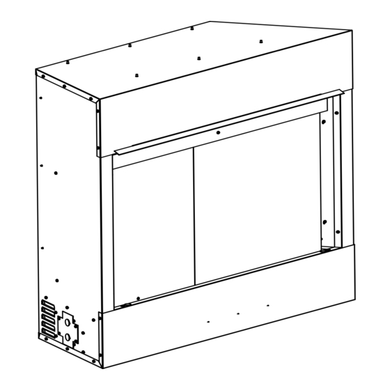
Page 4: Fireplace Dimensions
1/2" (13mm) 3³⁄₄" (95mm) 2¹¹⁄₃₂" (60mm) Fig. 1 Fireplace specifications and framing dimensions. Ref. BREF30/BREF30NH 34” (864 mm) 36” (914 mm) 30” (762 mm) 21” (533 mm) 7¹⁄₂” (191 mm) 19³⁄₄” (502 mm) 14” (356 mm) 27¹⁄₂” (698 mm) 36¹⁄₂” (927 mm) 35”... -
Page 5: Mantels
Mantels The height that a combustible mantel is fitted above the fireplace is dependent on the depth of the mantel. This also applies to the distance between the mantel leg (if fitted) and the fireplace. For correct mounting height and width, refer to Figure 2a and 2b. -
Page 6: Finishing
Fig. 3 Adjustable drywall strip (nailing flange). FP549 Finishing 9/29/97 BR/BC CAUTION: All joints between the finished wall and the appliance surround (top and sides) may be sealed only with noncom- bustible material. Only noncombustible material can be applied as facing to the appliance surround (the black painted face). -
Page 7: 240 Volt Wall Switch Wiring Installation
7. Connect the white wire from the unit to the neutral (white) wire on the power supply. 8. Connect the ground wire from the wall switch to the wire grouping from the power supply and the ground stud in the junction box. 9. -
Page 8: 120 Volt Unit Installation
120 Volt Unit Installation 1. Locate the switch under the logset on the left front corner of the unit. 2. Check the voltage selection switch position to ensure it is in the 120 Volt position. 3. Loosen the screws securing the junction box cover and remove the cover. -
Page 9: Screen Kit Installation
Screen Kit Installation 1. Remove the plastic bag from each screen. 2. Remove the four (4) metal clips, two (2) for each side of the fireplace opening. 3. Slide screen panels against sides of the fireplace opening. 4. Align each metal clip with the hole it was removed from, while at the same time, hooking the clip through the last wire of the screen. -
Page 10: Replacing Light Bulbs
8. Place the right front log (G5) in position on the ember lava rock. Use the notches under the log front right to have a proper location. Fig. 7 BREF42/BREF42R ceramic log placement. To reduce the risk of fire, electrical shock or personal injury, disconnect all power coming to the fireplace at the main service panel before attempting any maintenance... -
Page 11: Electrical Wiring Diagram Without Integral Remote Control W/Ceramic Log Set
Electrical Wiring Diagram without Integral Remote Control For Units with Ceramic Log Sets (Refer to Figures 6 & 7) 4 BLACK 21 WHITE 1. Heater Element 2. Limit Control, 175/20 DIF 3. Relay Switch, 120V 50/60Hz 4. Fan/Heater Motor 5. Thermostat 6. -
Page 12: Electrical Wiring Diagram With Integral Remote Control W/Ceramic Log Set
Electrical Wiring Diagram with Integral Remote Control For Units with Ceramic Log Sets (Refer to Figures 6 & 7) 4 BLACK 14 BROWN 25 RED 23 WHITE 1. Heater Element 2. Limit Control, 175/20 DIF 3. Relay Switch, 120V, 50/60Hz 4. -
Page 13: Electrical Diagram With Heater And Intregral Remote Control
Electrical Wiring Diagram with Heater and Integral Remote Control 4 BLACK 14 BROWN 25 RED 23 WHITE 1. Heater Element 2. Limit Control, 175/20 DIF 3. Relay Switching, 120V, 50/60Hz 4. Fan/Heater Motor 5. Thermostat 6. Switch, Rocker 7. Switch 8. -
Page 14: Electrical Diagram Without Heater And Integral Remote Control
Electrical Wiring Diagram without Heater and Integral Remote Control 7 WHITE 8 WHITE 1 BLACK Fig. 14 Wiring diagram for models without heat. (BREF30NH/BREF36NH/BREF42NH) 4 BLACK 3 BLACK BLACK 6 WHITE WHITE 2 BLACK BLACK 5 WHITE CFM Component Identification 1. -
Page 15: On/Off Switch
For units with ceramic log sets. This set of instructions applies to units with ceramic log sets. (Figs. 6 & 7) The control compartment is located inside the fireplace behind the steel curtain near the left front corner. To access the controls, simply slide the steel curtain open. -
Page 16: On/Off Switch
For all other units. The control compartment is located inside the fireplace behind the steel curtain near the left front corner. To ac- cess the controls, simply slide the steel curtain open. Control Panel 1. ON/OFF Switch 2. Heater Control Fig. -
Page 17: Replacement Parts
BREF36/BREF36R CFM Specialty Home Products reserves the right to make changes in design, materials, specifications, prices and discontinue colors and products at any time, without notice. BREF36/42, BREF36R/42R Electric Fireplace for Units with Ceramic Log Sets 10004758 4758 BREF older parts 5/05 BREF Electric Fireplace BREF42/BREF42R... - Page 18 BREF36/42, BREF36R/42R Electric Fireplace for Units with Ceramic Log Sets (continued) Ref. Description Log Set Complete Heater Element Motor, AC, w/Terminals Rocker Switch (Illuminated) Thermostat - Heater Control Fan w/Bracket Assembly Sensor, 230°F Manual Reset Knob - Flame Speed, Heater Controls Light Filter - Ember Bed (Not shown) Plate Control Assembly Screen Tinted Plastic (Not shown)
- Page 19 BREF30/36, BREF30/36NH BREF42/BREF42NH CFM Specialty Home Products reserves the right to make changes in design, materials, specifications, prices and discontinue colors and products at any time, without notice. BREF30/36/42, BREF30NH/36NH/42NH Electric Fireplace 10004758 4758 BREF parts 1/05 BREF Electric Fireplace ��...
-
Page 20: Accessories
BREF30/36/42, BREF30NH/36NH/42NH Electric Fireplace (continued) Ref. Description Log Set Complete Heater Element Motor, AC, w/Terminals Rocker Switch (Illuminated) Thermostat - Heater Control Fan w/Bracket Assembly Sensor, 230°F Manual Reset Knob - Heater Controls Plate Control Assembly Screen Tinted Plastic (Not Shown) Ember Lava Rock Flame Generator Assembly Support Plate... - Page 21 BREF Electric Fireplace 10004758...
- Page 22 BREF Electric Fireplace 10004758...
-
Page 23: Warranty
For MAJESTIC FIREPLACES BASIC WARRANTY: CFM Specialty Home Products (hereinafter referred to collectively as the "Company") warrants that your new Majestic Fireplaces fireplace is free from manufacturing ® and material defects for a period of one year from date of installation, subject to the following conditions and limitations. - Page 24 CFM Specialty Home Products 410 Admiral Blvd. • Mississauga, Ontario, Canada L5T 2N6 • 905-670-7777 www.majesticproducts.com • www.vermontcastings.com...