Advertisement
Quick Links
How To: Replace Adjustment Ring Interlock
Switch
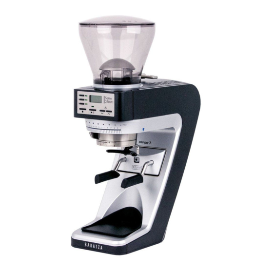
Sette 30, 270, 270W, 270Wi
Time: 30 minutes
Difficulty: Medium
Tools/Supplies: T-10 Torx Bit,
Parts: S032
Additional Resources: Sette Case Removal
There are two techniques to changing this switch. Technique 1 is faster but carries slight risk of
damaging the front silver case (while bending the case down as shown in step 5) and is only
recommended for technicians who are comfortable running the risk of causing damage.
Technique 2 requires more disassembly and is longer, but is less likely to cause damage to the
silver case. Please read both techniques to see which one is best for your skill level.
*** Unplug the grinder from power supply ***
1. Remove the case
2. -WARNING- Although the capacitor will be discharged unless there are
extenuating circumstances, exercise caution as it potentially has a high voltage
charge that can shock you if the contacts are touched.
www.baratza.com
Technique 1 (faster but more difficult)
support@baratza.com
rev. 9/12/2018
Advertisement

Summary of Contents for Baratza Sette 30
- Page 1 How To: Replace Adjustment Ring Interlock Switch Sette 30, 270, 270W, 270Wi Time: 30 minutes Difficulty: Medium Tools/Supplies: T-10 Torx Bit, Parts: S032 Additional Resources: Sette Case Removal There are two techniques to changing this switch. Technique 1 is faster but carries slight risk of damaging the front silver case (while bending the case down as shown in step 5) and is only recommended for technicians who are comfortable running the risk of causing damage.
- Page 2 3. Remove the adjustment assembly, unplug the red and black motor leads, remove the (4) screws indicated below, and lift out to remove the gearbox/motor assembly www.baratza.com support@baratza.com rev. 9/12/2018...
- Page 3 4. Remove the two short screws indicated below www.baratza.com support@baratza.com rev. 9/12/2018...
- Page 4 5. Gently but firmly bent the silver down and away from the black. Use a wedge to keep a gap between the silver and black portions of the case Burr being used as a wedge 6. Pry up the microswitch off the two posts it rests on by using a pick www.baratza.com support@baratza.com rev. 9/12/2018...
- Page 5 9. Install new switch on posts, taking care to orient the spring steel arm properly (reference photo above) 10. Remove wedge 11. Replace 2 small screws (do not overtighten) 12. Install gearbox/motor assembly 13. Install case www.baratza.com support@baratza.com rev. 9/12/2018...
- Page 6 1. Remove the case 2. -WARNING- Although the capacitor will be discharged unless there are extenuating circumstances, exercise caution as it potentially has a high voltage charge that can shock you if the contacts are touched. www.baratza.com support@baratza.com rev. 9/12/2018...
- Page 7 3. Remove the adjustment assembly, unplug the red and black motor leads, remove the (4) screws indicated below, and lift out to remove the gearbox/motor assembly www.baratza.com support@baratza.com rev. 9/12/2018...
- Page 8 7. Unplug the 2 pin and 3 pin Molex connectors from the PCB (not indicated – see step 19 for picture of these connectors) 8. You can lift out the felt rings (indicated with white arrows), or leave them in place. www.baratza.com support@baratza.com rev. 9/12/2018...
- Page 9 9. Lift up and remove the capacitor/PCB mount bracket -continued below- www.baratza.com support@baratza.com rev. 9/12/2018...
- Page 10 13. Remove the silver front casing. If the silver front casing does not easily remove, double check that all 14 screws securing it have been removed (2 under front feet, 10 in the back, 2 small screws right behind display) www.baratza.com support@baratza.com rev. 9/12/2018...
- Page 11 15. Pull the spade clip connectors to remove from the old switch. Push to insert connectors on to new switch. Install new switch on mounting posts, taking care to match the orientation of the spring-steel arm with the photo below. www.baratza.com support@baratza.com rev. 9/12/2018...
- Page 12 19. Place the capacitor/PCB bracket in position and inspect wires for routing issues 20. Install (10) screws in back of grinder (reference step 9, will need to slightly lift capacitor/PCB bracket to access top 2 screws) www.baratza.com support@baratza.com rev. 9/12/2018...
- Page 13 (2) wires into PCB noting that the power board to display wire inserts into the top port (reference step 7) 22. 270W and 270Wi have felt dampening rings between the gearbox/motor assembly and the chassis. Position as shown in step 8, then install the gearbox/motor assembly 23. Install case www.baratza.com support@baratza.com rev. 9/12/2018...


