Table of Contents
Advertisement
Quick Links
Advertisement
Table of Contents

Related Manuals for Uniden BCD996T


Summary of Contents for Uniden BCD996T
-
Page 2: Precautions
This might be particularly true of the type of earphone that is placed in the ear canal. WARNING! Uniden does not represent this unit to be waterproof. To reduce the risk of fire or electrical shock, do not expose this unit to rain or moisture. ®... -
Page 3: Power Related Issues
When you turn power back on, it resumes the previous mode. are registered trademarks of Uniden America Corporation. Precautions... -
Page 4: Table Of Contents
How the Scanner’s Controls Are Represented in This Manual ... 18 Entering Text Within A Menu Option ... 18 A Short User’s Guide to Assist the First-Time Scanner Enthusiast ... 19 Understanding Scanning and the BCD996T ... 21 Understanding the Scanner’s Memory ... 21 Understanding Quick Keys ... 21 What is Scanning? ... - Page 5 Setting Up an Audio Recording Device or Computer Recording ... 33 Vehicle Installation ... 33 Mounting Using the Bracket ... 33 Mounting Using the DIN-E Sleeve ... 34 Removing the Scanner from the DIN-E Sleeve ... 36 Mounting Using ISO Technique ... 36 Removing the Display Sticker ...
- Page 6 Setting the Serial Port Speed ... 58 Displaying Scanner Information ... 59 Viewing Memory Used ... 59 Viewing the Firmware Version and Electronic Serial Number ... 59 Initializing the Scanner’s Memory ... 59 Connecting Your Scanner to a Personal Computer ... 60 Volume/Squelch with PC Control ...
- Page 7 Setting Up Tone-Out ... 115 Tone-Out Multi-Channel Monitoring ... 117 Set Record ... 117 Using the BCD996T with a GPS ... 118 Device Compatibility ... 118 Connecting Your Scanner to a GPS Device ... 118 Initial Scanner/GPS Operation ... 118 Location-Based (GPS) Scanning ...
- Page 8 GPS Review Location Mode ... 125 Care and Maintenance ... 127 General Use ... 127 Location ... 127 Cleaning ... 127 Birdies ... 127 Troubleshooting ... 128 Specifications ... 131 Reference ... 134 Preset Fleet Maps ... 134 User Defined Fleet Maps ... 136 Type I Programming Information ...
-
Page 9: The Fcc Wants You To Know
The FCC Wants You To Know This scanner has been tested and found to comply with the limits for a scanning receiver, pursuant to Part 15 of the FCC Rules. These limits are designed to provide reasonable protection against harmful interference in a residential installation. - Page 10 up these transmissions. Do not open your scanner’s case to make any modifications that could allow it to pick up transmissions that are illegal to monitor. Modifying or tampering with your scanner’s internal components or using it in a way other than as described in this manual could invalidate your warranty and void your FCC authorization to operate it.
-
Page 11: Introduction
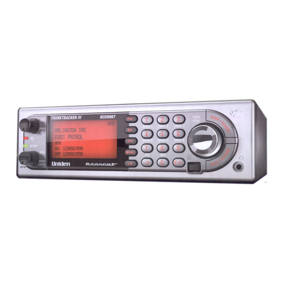
Your BCD996T scanner is a state-of-the-art scanner radio with Trunk Tracker IV™ and automatic scanning capabilities. You can store in the dynamic memory conventional frequencies such as police, fire/emergency, marine, air, amateur, and other communications. You can store and scan services that use Trunked Radio Systems and so much more. -
Page 12: Feature Highlights
Frequency (MHz) Lower Edge Upper Edge 806.0000 823.9875 849.0125 868.9875 894.0125 956.0000 1240.0000 1300.0000 Note: The scanner’s frequency coverage is not continuous and does not include the cellular telephone or UHF TV bands. Feature Highlights General DIN-E and ISO Vehicle Mountable — using an included DIN-E sleeve or a standard ISO technique, the scanner can be easily mounted in most vehicles. - Page 13 FM Broadcast, Military, Air, and Special searches, to make it easy to search for specific transmissions. “Soft” Search Keys — Lets you quickly search specified ranges. Channel Lockout — You can lock out any system, group, frequency, or channel while scanning. If you lock out a system or group, any channels belonging to that system or group are also locked out.
- Page 14 Custom Alerts — For each alert in the scanner (such as channel alert, Close Call alert, emergency alert), you can select from 9 different tone patterns and also set the alert volume level independently from the main volume level. Automatic Channel Step — Accepts frequencies on any valid channel step, even if it does not fall within the band plan’s default step.
-
Page 15: Gps
Multi-Site Trunking — Lets you share system channels across multiple sites to more efficiently use the scanner’s memory and more easily select sites to monitor. Control Channel Only Scanning — If the scanner is set to scan a Motorola system, you can set it so it scans using only control channel data. You do not have to program voice channel frequencies into memory in this mode as long as all possible control channels are programmed. -
Page 16: Auto Store
Internet and load them into the scanner. Free PC control and programming software will be available at http://www.uniden.com. Clone Mode — You can clone all programmed data, including the contents of the scanner’s memory, menu settings, and other parameters from one BCD996T scanner to another BCD996T scanner. -
Page 17: Memory Storage Limits
The Scroll Control is a dual purpose control. It also lets you switch to secondary function operations. When used in this manner, you see prominently on the right of the BCD996T’s front panel, the knob/switch lets you easily control channel selection, plus Normal and Function Modes, as well as how most of the information appears on the display. -
Page 18: How The Scanner's Controls Are Represented In This Manual
Scroll Control again. f flashes at approximately 1 second intervals. If you select Function while scanning, the BCD996T continues to scan, but holds on the current system until the function operation is cancelled. -
Page 19: A Short User's Guide To Assist The First-Time Scanner Enthusiast
Page 139, you are ready to enter the exciting world of trunk tracking. Uniden has made it easy for you to start scanning. We have preprogrammed the BCD996T with more than 500 agencies across the U.S. If you live in one of the preprogrammed areas, simply press [SCAN/SEARCH] to start scanning. Then, press [.No] and the two-digit quick key for your area. - Page 20 Don’t be overwhelmed. Begin by choosing the Talkgroups of interest to you. Begin by transferring the data from the Radio Reference website to the worksheets you obtain from the Uniden website and from there, to the scanner. You can visit one of the Radio Reference forums and potentially learn of someone in your immediate area who has programmed the same model scanner in your area.
-
Page 21: Understanding Scanning And The Bcd996T
Traditional “Banked” scanners let you select and deselect banks by pressing a single digit on the keypad. The BCD996T uses a similar method to turn on and off scanning sites and systems. When you program a system or site, you assign a quick key (System/Site Quick Key, or SQK) from 0 to 99. -
Page 22: What Is Scanning
What is Searching? The BCD996T can search each of its 13 service search ranges and up to 10 custom search ranges to find active frequencies. This is different from scanning because you are searching for frequencies that have not been programmed into the scanner’s channels. -
Page 23: Conventional Scanning
A scanner, such as your BCD996T, equipped with CTCSS and DCS, can code each received frequency with a specific sub-audible CTCSS or DCS frequency or code. -
Page 24: Repeater Operation
Typical repeater systems provide coverage out to about a 25-mile radius from the repeater location. What is Trunk Tracking? Your BCD996T is designed to track the following types of trunking systems. • Motorola Astro 25 (APCO 25) trunking systems. • Motorola Type I, Type II, Type IIi hybrid, SMARTNET, and PRIVACYPLUS analog trunking systems, which are extensively used in 800 MHz communication systems. -
Page 25: Trunked Scanning
This semi-random frequency assignment made monitoring such a system impossible prior to Uniden’s invention of the TrunkTracker scanner. Not only does your BCD996T scan channels like a conventional scanner, it actually follows the users of a trunked radio system. Once you know and program a talk group’s ID (TGID), you won’t miss any of the action. -
Page 26: Edacs Trunking
Talk groups are assigned in an Agency-Fleet-Subfleet (AFS) hierarchy.There is one variation of EDACS called SCAT that your BCD996T can monitor. Logical Channel Numbers — each frequency used by the system is assigned an LCN. This information is programmed into each user radio. When a user presses PTT, their radio sends their AFS information to the control channel. -
Page 27: Ltr Trunking
While your BCD996T cannot track ID’s in this system, it can eliminate the control data so that all you hear is the voice transmissions when you monitor this type of system. -
Page 28: Startup Configuration
data matches a talk group ID that you have stored in the talk group ID list and have not locked out. LTR systems are frequently programmed so that each radio has a unique user ID. Startup Configuration Setup/Operation The Startup Configuration option lets you quickly and automatically lock and unlock systems based on your desired configuration. -
Page 29: I-Call (Motorola/Edacs)
I-Call (Motorola/EDACS) I-calls are direct unit-to-unit transmissions that are not heard by other system users. Your BCD996T can receive I-call transmissions. See “Setting I-Call (Motorola and EDACS Systems Only)” on Page 72 for more information about monitoring I-call transmissions. Where To Get More Information By itself, this manual only provides part of what you need to know to have fun scanning —... -
Page 30: Included With Your Scanner
Cable (scanner plug to Front PC Connecter) If any of these items are missing or damaged, immediately contact your place of purchase or Uniden Customer Service at: (800) 297-1023, 8:00 a.m. to 5:00 p.m., Central, Monday through Friday. AC Adapter (P/N AD-1009) Three Wire DC Power Cord —... -
Page 31: Setting Up Your Scanner
These guidelines will help you install and set up your new scanner: The BCD996T can be placed on a convenient surface in your home as a base station, and connected to a standard outlet that supplies 120VAC, 60Hz. You must use either the supplied antenna or an electrically correct outdoor antenna, properly and safely mounted at your chosen site. - Page 32 13.8V, 750 mA AC adapter. Insert the barrel of the AC adapter to the jack on the rear, upper right side of the radio marked WARNING! Use only the Uniden-supplied AC adapter with this scanner. Mounting Feet (4) Apply beneath the bracket;...
-
Page 33: Setting Up An Audio Recording Device Or Computer Recording
Insert the connector of the supplied indoor telescoping antenna to the BNC Antenna Connector and apply moderate pressure to secure it. Setting Up an Audio Recording Device or Computer Recording It is best if you plan ahead when you initiate the basic setup of the scanner if you include the components to record incoming reception. -
Page 34: Mounting Using The Din-E Sleeve
Your scanner requires a 2 x 7-1/8 x 5-5/16 inch (50 x 180 x 135 mm) mounting area. Allow an additional 2-3/8 inch (60 mm) space behind the unit for connectors and wires. Bracket Mounting Screws BCD996T Star Washers... - Page 35 Note: if you plan to connect a GPS unit or external speaker at a later time, expect to remove the unit for ease of making those connections. Opening in dash DIN-E Sleeve BCD996T with outer case removed Setting Up Your Scanner...
-
Page 36: Removing The Scanner From The Din-E Sleeve
Slide the cover toward the rear and off. Once the sleeve is removed, you will see threaded, metric machine screw holes on either side of the chassis cabinet. Uniden does not supply these screws. Their diameter, length, and screw type should be chosen by a qualified installer based on the internal vehicle bracket... -
Page 37: Removing The Display Sticker
Once the original radio is removed from the vehicle dash and the fit of the scanner is correct, be sure to connect all the power, audio, antenna, and any other cables or wires, to the scanner before the scanner is secured. The following illustration is a typical example of the ISO technique and the general side mounting screw holes often encountered. -
Page 38: Connecting An Extension Speaker
WARNING! Never connect anything other than the recommended amplified extension speaker to the scanner’s headphone jack. Damage to the scanner might occur. Connecting an Extension Speaker In a noisy area, an optional amplified extension speaker, positioned in the right place, might provide more comfortable listening. Plug the speaker cable’s (3.5-mm) mini-plug into your scanner’s back-panel Ext. -
Page 39: Controls, Keys, And Functions
Record Out External Spkr The knobs and keys on the BCD996T produce several different actions. You can, for example, rotate the knobs as well as press them to achieve a different result. Pressing a key briefly can produce one result while pressing and holding, gives a different result. - Page 40 Control/Key Label [Power/VOL] Squelch Scroll Control and Function [PRI] Mode Action Rotate Press Press F Function then tap VOL Rotate Scroll Control Rotate Press Press & Hold Press Rotate Scan or Scroll Control Custom + Rotate Search Hold Rotate Menu Rotate Press Name Edit...
- Page 41 Control/Key Label [WX] WX Scan or WX Alert Scan Other [GPS] [L/O] Scan Search Hold Menu Scan/ Scan Hold Search Search Hold Close Call Only Close Call Hold Mode Action Press Toggle between WX Scan and WX Alert Scan Press Turn to toggle WX Alert Priority On and Press &...
- Page 42 Control/Key Label [0] to [9] [4] move left [6] move right [.No] Mode Action Scan Press Custom Press Search All Hold Press Close Call Tone-Out F + Press Scan F + Press [1] Other than Scan or GPS to [6] F + Press [7] Other than Scan or GPS...
- Page 43 Control/Key Label MENU Scan Scan Hold Search Search Hold Close Call Close Call Hold WX Scan WX Scan Hold Tone-Out Standby [SCAN/SEARCH] 11 Scan Hold Other than Scan or Scan Hold or Search Hold Trunking Scan [HOLD/RESUME] 12 Scan Search Close Call Only WX Scan...
-
Page 44: A Look At The Display
A Look At The Display The display has indicators that show the scanner’s current operating status. The display information helps you understand how your scanner operates. The LCD screens shown here are only a few of many that you will see while in different modes. -
Page 45: Operation
Turning On the Scanner and Setting the Squelch To turn the scanner on, rotate [VOL] clockwise. Turn the knob to a comfortable sound level. Rotate the squelch control [SQ] clockwise until you either hear a broadcast or noise just stops. The control is now set for strong signals. If you desire to hear a weaker signal, turn it counter clockwise from that point until you hear background noise once more. -
Page 46: Scanning Systems
• Within a system, channels are scanned according to the assigned channel group, with the same priority as described above for systems. • The BCD996T scans a system for the duration you set using the System Hold Time option (see “Setting the System Hold Time” on Page 70). For trunked systems, the scanner moves to the next system after the hold time expires, the current transmission ends, and the channel delay expires. -
Page 47: Preprogrammed System Tips
Preprogrammed System Tips All systems preprogrammed into the scanner are assigned to a Quick Key. See “Preprogrammed Systems with Quick Keys” on Page 139 for a list of preprogrammed systems and their Quick Key assignments. Notes: • The systems preprogrammed into the scanner are located primarily in major metropolitan areas. -
Page 48: Locking/Unlocking Systems
Locking/Unlocking Systems Follow these steps to lock out a system so that it does not scan even if its quick key is selected. 1. Tap to switch to the Function Mode then rotate the control to select the desired system. 2. -
Page 49: Holding On A System
To toggle between ID Scan and ID Search, press while the scanner is scanning the system. If the scanner does not scan the system long enough for you to easily do this, press and rotate the Scroll Control to select the changed system. Then, press [SCAN/SEARCH] within 2 seconds. -
Page 50: Trunking Activity Indicators
If you enter a frequency then press [E Grp group in a system called Qck Save Cnv Sys. These groups are created if they do not exist. Then, the scanner prompts you to save other channel settings. If you enter a talk group ID then press [E group named Qck Save Grp in the current system. -
Page 51: Toggling The Display Mode
Toggling the Display Mode To change the display so the channel and frequency or Talk Group ID appear instead of extended channel information, hold on any channel then press + [0]. The scanner displays Display Mode 2. To return to Mode 1, press + [0] Mode1 indicates the channel data under the Channel Name. -
Page 52: Optimizing P25 Performance
Optimizing P25 Performance You can optimize the scanner’s performance with digital APCO 25 systems. Follow these steps for each system where you can hear APCO 25 traffic. Notes: These steps work only when you can clearly receive the system. If you are in a weak-signal area or receive interference, these steps will not work. - Page 53 • The next to last line on the display now shows the digital error rate and the AUTO decode threshold start level (0-20). • The last line on the display shows the decode threshold levels for the system. Allow the scanner to monitor channel activity for several minutes. The error rate should drop for each transmission and the threshold levels should automatically adjust to a more optimal setting.
-
Page 54: Using The Menu
The BCD996T incorporates an effective menu system that lets you make all the necessary setting options required to program the scanner and effectively use the many features. To use the menu, press [MENU]. You immediately see the screen display the menu title at the top and three of ten menu options beneath. -
Page 55: Programming General Settings
Programming General Settings This section covers your scanners general settings. Setting and Using the Backlight The LCD has a backlight that can be set to green or red with three levels of intensity for each color plus OFF. To make your selection, press [VOL]. Each time you press the control, the backlight cycles in the following order. -
Page 56: Setting The Backlight Color
Manual — Use this setting to manually set the dimmer level to High, Middle, Low, or Off. To guide you in your selection, at each setting the display shows what you can expect to see. Setting the Backlight Color [MENU] Settings Set Backlight Set Color... -
Page 57: Setting The Display Orientation
Setting the Display Orientation [MENU] Settings Set Upside-down This setting controls the orientation of the display. If you set Upside-down to On, the scanner inverts the display text and graphics. Adjusting the Display Contrast There are 15 contrast levels. As you scroll from level 1 to 15 you see the contrast change. -
Page 58: Setting The Time Format
This setting controls the format used for displaying the time on the GPS data screens. 12H — the scanner displays time in 12-hour format using am for mornings and pm for evening times. 24H — the scanner displays time in 24-hour format using 0 for midnight and 23 for 11 pm. -
Page 59: Displaying Scanner Information
For Serial Port Speed (Baud Rate), select from 4800 bps 9600 bps 19200 bps 38400 bps 57600 bps 115200 bps Displaying Scanner Information Viewing Memory Used [MENU] Settings See Scanner Info % Memory Used The scanner displays the percent of memory that is used and the number and the percent of systems, sites and channels that are created. -
Page 60: Connecting Your Scanner To A Personal Computer
Wired Cloning Using the scanner in a cloning setup lets you transfer programmed data directly from a source or master BCD996T to a target or slave BCD996T. Wired cloning between other models to the BCD996T is not possible. [MENU]... - Page 61 gender changer (neither included), available at most computer stores. Then you must set one scanner as the source and the other as the target. 1. Select the Front Port for the Master. Select the Rear Port for the Slave or vice versa.
-
Page 62: Programming Your Scanner
Programming Your Scanner Your BCD996T comes preprogrammed with over 500 state and local agencies, both analog and digital, selected from the most populous areas in the US. This should let you get started quickly to enjoy your new scanner. However, to get the most enjoyment from your scanner (especially if you do not live near one of these counties), you must customize the programming for your area. -
Page 63: System Settings
System Settings System Settings • Edit Name Edit Sys • Option Edit Site Edit Group • Copy System • • Delete System System Options System Option Settings • Set Quick Key • Set Startup Key • Set Lockout Set Hold Time •... - Page 64 System Option Settings Set I-Call Emergency Alert EDCS ID Format • Set Record Rvw ID:Srch Clr All L/O IDs • Adjust P25 Level MOTOROLA P25/ WIDE/ TYPE I TYPE II NARROW • • • • • • • • • •...
-
Page 65: Site Settings
Site Settings MOTOROLA TYPE I Site Setting 800MHz 800MHz Standard Splinter • Edit Name • Set Quick Key • Set Startup • Frequencies • Set Modulation • Set Attenuator • Set Lockout Set Hold Time • Edit Band Plan • Set C-Ch Only •... -
Page 66: Channel Settings
Channel Settings Channel Setting • Edit Name Edit Frequency • Edit TGID Set Audio Type • • Set Modulation • Set Attenuator Set Priority • Set Alert • Set Record • • Set Lockout • Copy Channel • Delete Channel New Channel •... -
Page 67: Programming Trunked Radio Systems
Programming Trunked Radio Systems [MENU] Program System New System Then, select the system type: MOT TYPE 1 — Motorola Type I systems MOT TYPE 2/P25 — Motorola Type II and APCO 25 systems EDCS WIDE/NARROW — EDACS Wide and Narrow systems EDCS SCAT —... -
Page 68: Specifying The Correct System Type
Specifying the Correct System Type In order for trunk tracking to work properly, you have to specify the correct system type when you create the system. Here are some tips for selecting the correct type: • Use online resources, such as the www.radioreference.com database, to identify the system type. - Page 69 Notes: • Access single-digit system/site Quick Keys by pressing the single digit on the keypad during scanning. Access two-digit system Quick Keys by pressing [.No] then both digits. • You can assign as many systems to the same quick key as you want. •...
- Page 70 Setting the System Hold Time [MENU] Program System Select a conventional system Edit Sys Option Set Hold Time Set how long the scanner will remain scanning on this system before moving to the next system (up to 255 seconds). Note that the scanner will scan all unlocked channels at least one time, regardless of the system hold time setting.
- Page 71 This setting controls whether the scanner automatically skips channels it identifies as data. This includes channels with either no audio or a constant-level audio source. If turned on, the scanner resumes scanning as soon as it detects the data signal. Setting Location Information [MENU] Program System...
- Page 72 Setting the Status Bit [MENU] Program System Select a Motorola Type I or II system Edit Sys Option Set Status Bit Ignore — the scanner rounds all received ID’s down to the next interval of 16. The default setting is Ignore. Yes —...
- Page 73 Off — the scanner ignores I-calls. The default setting is Off. Only — the scanner only tracks I-calls and ignores other radio traffic on the system. Press to select. Note: To set the I-Call to a wildcard receive condition, press [.No] + [0]. Setting the Emergency Alert Option [MENU] Program System...
- Page 74 Setting the System Record Option [MENU] Program System Select a system Edit Sys Option Set Record This setting controls how the scanner handles the record option for channels in the system. All Channel — The scanner sends the audio for all channels in the system to the REC jack, regardless of the channel’s record option setting.
- Page 75 Adjust the P25 Decode Threshold [MENU] Program System Select a conventional system Edit Sys Option Adjust P25 Level This setting determines some system-specific parameters for digital channels. In most cases, setting this to Auto provides the best performance. However, you can also manually set the digital decode threshold.
-
Page 76: Programming Sites
Copying Systems Occasionally you might want to copy and rename a system to highlight one group over another. One system might be called City - Fire and the same system City - PD with adjustments to data within. This lets you quickly locate the desired set of data. To copy a system including all settings, groups, and channels: [MENU] Program System... - Page 77 MS1: Motorola 800 MHz Type I Standard MS2: Motorola 800 MHz Type II Standard MP1: Motorola 800 MHz Type I Splinter MP2: Motorola 800 MHz Type II Splinter P25: APCO 25 (all bands) M92: Motorola 900 MHz MV2: Motorola VHF MU2: Motorola UHF EDW: EDACS Wide EDN: EDACS Narrow...
- Page 78 Notes: • Access single-digit system/site Quick Keys by pressing the single digit on the keypad during scanning. Access two-digit system Quick Keys by pressing [.No] then both digits. • You can assign as many systems to the same quick key as you want. •...
- Page 79 Note: If you select Control Channel Only mode (see “Setting Control-Channel Only (Motorola Systems Only)” on Page 81), you only need to enter the frequency(s) that can be assigned as the control channel. Most frequency lists usually indicate which of the frequencies are the control channel frequencies. Otherwise, you must enter all of the frequencies.
- Page 80 Edit Site Select a site Set Lockout Select from the following choices then press Unlocked — the system is scanned when its quick key is enabled. Temporary L/O — the system is locked for this session. Lockout — the system is not scanned. Setting Site Hold Time [MENU] Program System...
- Page 81 Base Frequency, Channel Step, and Channel Offset for the site. Setting P25 Band Plans The BCD996T includes two operation modes for P25 systems: explicit mode and implicit mode channel assignment. Explicit mode systems include all information needed to determine voice frequencies on the control channel. You must supply the system’s band plan for implicit systems for the scanner to correctly determine...
- Page 82 Select a non-P25 site Set C-Ch Only This setting determines the frequencies you need to enter for Motorola systems. Select your setting, then press On — You only need to enter control channel frequencies. Off — You must enter all voice and control channel frequencies. Note: The scanner defaults to On.
-
Page 83: Programming Channel Groups
manually set the digital decode threshold. This setting affects all channels in the current site. See “Optimizing P25 Performance” on Page 52. Auto — the scanner automatically adjusts the digital decode threshold to match the transmission you are hearing when it receives a strong signal and has a high decode rate. -
Page 84: Setting The Group Quick Key
Select a New Group Edit Name Follow these steps to enter/edit the group name. 1. The current name displays with the first character of the name highlighted. 2. Rotate the Scroll Control to select a new first letter. Press [6] to move one character to the right. -
Page 85: Deleting Channel Groups
Select an existing group Set Lockout This setting determines whether the scanner will scan this group of channels. Select your setting, then press Lockout — the group is not scanned. Temporary L/O — the group is not scanned for this session. The L/O is cancelled when you cycle power. -
Page 86: Editing Frequencies
Edit Group Select the channel group Edit Channel Select the channel Edit Name Follow these steps to enter/edit the channel name. 1. The current name displays with the first character of the name highlighted. 2. Rotate the Scroll Control to select a new first letter. 3. -
Page 87: Setting The Audio Type
Editing the Talk Group ID [MENU] Program System Select a trunked system Edit Group Select a channel group Edit Channel Select the channel Edit TGID To edit the Talk Group ID, enter the Talk Group ID you want using the number keys. -
Page 88: Quick Ctcss/Dcs Save
Edit Group Select the channel group Edit Channel Select the channel Set Audio Type Analog Only At this point you can scroll to CTCSS or DCS and select the subaudible frequency in the CTCSS range or the DCS code. CTCSS or DCS This setting controls how a sub audible CTCSS or DCS is used for the channel. -
Page 89: Setting Channel Attenuation
Select the Channel Set Modulation Auto — the scanner uses the default modulation for the channel. The default setting is Auto. AM — the scanner uses AM (amplitude modulation) for the channel. FM — the scanner uses FM (frequency modulation) for the channel. NFM —... -
Page 90: Setting Channel Alert
Select the channel Set Priority This setting controls whether the scanner treats the channel as a priority channel while scanning. Select On or Off, then press On — when you turn on the Priority feature, the channel will be scanned every 2 seconds. - Page 91 On — the scanner outputs the signal. Off — the scanner does not output any audio. Note: In order for the function to work, you must set the channel to record. You must also set the system’s record option to either All Channel (which will record all channels regardless of the channel’s record setting) or Marked Channel (which only records the channels you’ve set to record).
- Page 92 Edit Group Select a channel group Edit Channel Select a channel Delete Channel You see Confirm Delete? Yes= ”E” / No= ”.” Select one to delete the channel or to cancel.
-
Page 93: Searching And Storing
Searching and Storing Service Search Service Search lets you select and search the scanner’s preprogrammed search ranges. During service search, the scanner searches starting with the lowest frequency in the search range you select to the highest frequency in the range. There are two ways to do this. -
Page 94: Quick Search
To lock out a frequency found while searching, press [L/O] one time to temporarily lock it out (Temporary L/O appears) or twice to permanently lock it out (Locked Out appears). Notes: • If all frequencies in the search range you selected are locked out, All Locked! appears and the scanner does not search the range. -
Page 95: Editing A Custom Search Range
The scanner starts custom search of the custom search range you selected, stopping on any transmission it finds and displaying the frequency. Turn the Scroll Control to change the search direction. An arrow appears, showing the current search direction. To turn search ranges on or off, press [0] and [1] - [9]. To hold searching, press [HOLD/RESUME]. -
Page 96: Search With Scan
Set Hold Time — sets how long (seconds) the custom search range is checked before the scanner moves to the next programmed entry. Search With Scan When you press [SCAN/SEARCH] the BCD996T starts a scan of those sites, channels, etc you have manually programmed or the Uniden preprogrammed data... -
Page 97: Editing A Service Search
for your metropolitan area that are unlocked and have their System Quick key enabled. In addition to this scan you can search any of the preprogrammed service or custom search ranges. While scanning, press service or custom search range. Press [L/O] to unlock it. You can also assign a System Quick Key to the search to make it easy to quickly enable/disable the search range for search and scan. -
Page 98: Set Delay Time
Set Delay Time Choose a delay time to set how long the scanner stays on a transmission after it ends. to select a value from 1 sec, 2 sec, 3 sec, 4 sec, 5 sec, and Off. Set Attenuator Choose to attenuate all frequencies by about 20 dB. to select to choose an attenuation for all frequencies in the range. -
Page 99: Saving A Found Channel (Quick Save)
Saving a Found Channel (Quick Save) If you hold on a channel or receive a desired channel, you can save it by pressing ] instead of using Direct Entry. The alpha data is also stored. If a GPS unit is attached, the longitude and latitude data is saved and becomes the name of that channel. -
Page 100: Trunked Search And Store
line changes to Memory Check when the scanner detects a transmission while it is checking to see if the frequency has already been stored. When the scanner finds an active transmission, it checks to see if the frequency has already been stored in the system. If it has already been stored, the scanner continues to search. -
Page 101: Using The Close Call Feature
Using the Close Call Feature Your scanner’s Close Call™ feature lets you set the scanner so it detects, displays the frequency of, and lets you hear a nearby strong radio transmission. You can set the scanner so the Close Call feature works “in the background” while you are scanning other frequencies, turn off normal scanning while the Close Call feature is working, or turn off the Close Call feature and use the scanner normally. - Page 102 Call mode and stores any Close Call hits, up to the maximum you specified in the Max Auto Store setting. If the scanner stores more hits than this setting, it stops auto store operation. Turn the Scroll Control to display an option, then press Set CC Mode —...
-
Page 103: Close Call Hits
Set CC Bands — Lets you select the Close Call band settings. You can turn the following bands on or off. VHF Low 1 — (25.0000 - 53.9800 MHz) VHF Low 2 — (54.0000 - 107.9000 MHz) Air Band — (108.0000 - 136.9750 MHz) VHF High 1 —... - Page 104 resuming scan. This lets you continue to hear transmissions detected with the Close Call feature, even after you are no longer close enough to receive it as a Close Call hit. Follow these steps to set up the option. [MENU] Close Call Hits with Scan Set Quick Key or Set Lockout or Set Hold Time...
-
Page 105: Search And Close Call Options
Search and Close Call Options The settings in this section affect custom searches, service searches, and Close Call operation. The following table shows what options are available for various search modes. Service Setting Search Freq. Lockouts • Broadcast Screen CTCSS/DCS •... -
Page 106: Unlocking All Frequencies
Unlocking All Frequencies [MENU] Srch/CloCall Opt Freq Lockouts Unlock All The scanner prompts you to confirm the change in lockout status. To confirm the change of all locked-out frequencies, press see Nothing Locked Press Any Key. Otherwise, to cancel, press [MENU]. Reviewing Locked-Out Frequencies [MENU] Srch/CloCall Opt... -
Page 107: Finding Repeater Output Frequencies
This setting determines whether the scanner automatically ignores transmissions found during Custom Search, Quick Search, or Close Call operation that are on common broadcasts, paging systems, and other annoyance radio sources. Note: Broadcast screening does not work in All service search ranges. Set All Band On —... -
Page 108: Setting The Maximum Auto Store Value
Repeater Find On or Off This feature sets whether the scanner tries to tune to a repeater output frequency during Custom Search, Quick Search, or Close Call operation when it detects a transmission on a repeater input frequency. Since you can normally only hear one side of a conversation when you listen to an input frequency transmission, turning this feature on can let you hear both sides of the conversation where a standard difference frequency is set between the input and the output, to and from the... -
Page 109: Setting Attenuation
AM — the scanner uses AM (amplitude modulation) for the frequency band. FM — the scanner uses FM (frequency modulation) for the frequency band. NFM — the scanner uses narrowband FM for the frequency band. WFM — the scanner uses wideband FM for the frequency band. WFM (Broadcast) —... -
Page 110: Setting The Delay Time
Setting the Delay Time [MENU] Srch/CloCall Opt Set Delay Time This setting determines how long the scanner waits after a transmission ends before resuming Quick Search or Close Call operation. 1-5 sec — The scanner waits the set amount of time after the transmission ends before resuming. -
Page 111: Adjust P25 Level
Adjust P25 Level You can select the best threshold for the APCO mode. [MENU] Srch/CloCall Opt Adjust P25 Level Auto — The automatic adjust feature is enabled. Manual — you can set the threshold manuals depending on your circumstances. Default — sets the factory default value. Note: Applies to P25 signals received during Search and Close Call. - Page 112 Using Weather Alert (SAME) Your BCD996T has been primarily designed as a multi-band, general services scanner. While it incorporates a weather alert ability as one of its features, we recommend that you not use the scanner as your sole means for receiving emergency alerts.
-
Page 113: Using Weather Alert (Same)
Turning Weather Alert On/Off In weather alert mode, your scanner functions as a severe weather warning radio. This is especially useful when your area is expecting severe weather conditions late at night. When you set the scanner to weather alert mode, it holds on the weather channel, but does not play the channel’s audio. -
Page 114: Turning Weather Alert On/Off
n: A special sub-county designator. For an entire county, use 0. SS: The state code. CCC: The county code. For example, Tarrant County in Texas is assigned to FIPS code 048439. 0 indicates the entire county 48 indicates the state of Texas 439 indicates Tarrant County To get the FIPS code for your county, visit the National Weather Service web site at http://www.nws.noaa.gov and search for “FIPS Listing”. -
Page 115: Fire Tone-Out
[SQ]. You need tone-out setup information from the agency you wish to monitor. Check with your local agency or on-line resources as Uniden America Corporation has no information regarding local tone-out systems. Setting Tone-Out Standby [MENU] Tone-Out for... - Page 116 • Edit Frequency — Enter the desired frequency that the scanner should monitor for the tone-out. • Set Modulation — Set the modulation type for the paging signal. Next choose the modulation setting: • Auto — The scanner uses the default modulation for the frequency band. If the default modulation is AM, WFM, or FMB, the modulation operates as •...
-
Page 117: Tone-Out Multi-Channel Monitoring
After you select an alert pattern, the scanner prompts for the alert level for a received alert. Level options 1 to 15 sets a fixed audio level independent of the main volume setting. AUTO uses the main volume setting for the alerts. Tone-Out Multi-Channel Monitoring The scanner can check multiple tone combination pages for channels whose settings are the same. -
Page 118: Using The Bcd996T With A Gps
Using the BCD996T with a GPS The scanner lets you connect a compatible GPS device to it to provide two very convenient operation features: • automatically locks and unlocks systems and sites based on data you input. This fine-tunes the scanning operation and makes it that much enjoyable. -
Page 119: Location-Based (Gps) Scanning
Location-Based (GPS) Scanning The BCD996T uses data, supplied by an attached GPS unit, that lets the radio automatically unlock and lockout sites based on the geographical information you provide. • Latitude (the center of the range or site) • Longitude (the center of the range or site) •... -
Page 120: Another Example Of Multiple Site Creation
Non-Radio Location Based GPS Features When connected to a GPS, you can program specific location information which will trigger an alert from the scanner. The scanner becomes an extension of the GPS device. The following geographical values are typical of use you might find valuable while traveling. - Page 121 Set Range Set Speed Limit Set Lockout Dangerous Xing • • • • • • • • • • • • • • • • Dangerous Road • • • • • • • • Using the BCD996T with a GPS...
-
Page 122: Setting The Options
Menu Option Delete Location Setting the Options [MENU] Program Location Select a location type (POI, Dangerous Xing, or Dangerous Road). New Location The scanner assigns a sequentially created number to the location. Edit Name Use the Scroll Control and example, enter the name of the place or the Route Number. At this level you have an opportunity to reassign or edit the Set Type location type you first selected and set the location to either one of the other types... -
Page 123: For Dangerous Xing, And Dangerous Road Only
You are alerted when you come within range of your set distances. Select from 15 sound levels, plus Auto and Off. As You can input the compass direction to the site from your Using the BCD996T with a GPS... -
Page 124: Gps Display Mode
+ [GPS] to toggle the Display mode in order. GPS DATA Display Choose from 0, through 100 MPH in 5 MPH steps or The BCD996T, a GPS, and a Dangerous Road Car One Car One is driving south. Car Two is driving east. -
Page 125: Gps Review Location Mode
— select a programmed location from all stored locations. The location data is stored in the order POI, Dangerous Xing, and Dangerous Road. Then, in each category, the data is stored using the programmed name. Using the BCD996T with a GPS... - Page 126 1. POI — Indicates a Point of Interest location. 2. DXG — Indicates a Dangerous Crossing location. 3. DRD — Indicates a Dangerous Road location. 4. Range — Indicates the programmed distance to your POI. 5. Head — Indicates the selected heading to the designated Dangerous Crossing from any direction.
-
Page 127: Care And Maintenance
Do not use excessive amounts of water. Repairs Do not attempt any repair. The scanner contains no user serviceable parts. Contact the Uniden Customer Service Center or take it to a qualified repair technician. Birdies All radios can receive “birdies” or undesired signals. If your scanner stops during Scan mode and no sound is heard, it might be receiving a birdie. -
Page 128: Troubleshooting
From time to time, Uniden might update the BCD996T’s firmware to change the scanner’s performance or incorporate new features. These updates can be applied by you using the supplied PC cable and the software that we will provide. Please note that firmware data must be input by means of the front panel serial cable connection, not the rear connector. - Page 129 Enter the data frequency. Change to a Type 1 scanner setup. See the programming instructions on the web at www.uniden.com/scanners. Set the scanner to scan LTR or EDACS systems. See the programming instructions on the web at www.uniden.com/scanners.
- Page 130 If you still cannot get satisfactory results while using your scanner or if you want additional information, please call or write the Uniden Parts and Service Division. The address and phone number are listed in the Warranty at the end of this manual.
-
Page 131: Specifications
Certificated accordance with FCC Rules and Regulations Part 15 Subpart C as of date of manufacture. Dynamic Allocation Capacity Systems : Groups : Site : Channels : Channels per Trunked System : up to 250 Band Coverage : Frequency Range : Range (MHz) 25.0000 to 26.9600 26.9650 to 27.4050... - Page 132 Range (MHz) 764.0000 to 775.9875 794.0000 to 805.9875 806.0000 to 823.9875 849.0125 to 868.9875 894.0125 to 956.0000 1240.0000 to 1300.0000 Sensitivity (nominal) 12dB SINAD : 0.4µV 25 - 27.995 MHz 0.3µV 28 - 53.98 MHz 0.7µV 54 - 71.95 MHz 0.3µV 72 - 75.995 MHz 0.6µV...
-
Page 133: Specifications
Features, specifications, and availability of optional accessories are all subject to change without notice. Contact your local Uniden Dealer or call the Uniden Parts Center at: (800) 554-3988, 8:00AM to 5:00PM EST, Monday through Friday, for information about ordering these optional accessories. -
Page 134: Reference
Preset Fleet Maps Note: Size Codes in parenthesis indicates that the Size Code spans more than one block. Preset Map 1 Block Size Code Size Code 11 Size Code 11 Size Code 11 Size Code 11 Size Code 11 Size Code 11 Size Code 11 Size Code 11 Preset Map 3... - Page 135 Preset Map 7 Block Size Code Size Code 10 Size Code 10 Size Code 11 Size Code 4 Size Code 4 Size Code 4 Size Code 4 Size Code 4 Preset Map 9 Block Size Code Size Code 4 Size Code 4 Size Code 0 Size Code 0 Size Code 0...
-
Page 136: User Defined Fleet Maps
Preset Map 15 Block Size Code Size Code 4 Size Code 4 Size Code 4 Size Code 11 Size Code 11 Size Code 0 Size Code 12 (Size Code 12) User Defined Fleet Maps Type I Programming Information When a Type I system is designed, the address information for all the ID’s is divided into 8 equal sized blocks, numbered 0–7. -
Page 137: Size Code Restrictions
seems. Select a size code for a block, and then press Scan. Now listen to the communications. If you decide you are receiving most of the replies to the conversations with ID’s assigned to the block you just programmed, then you’ve probably selected the right size code and can work on the next block of the map. -
Page 138: Preprogrammed Systems And Lockout Options
• Data used for the preprogrammed information was supplied courtesy of http://www.radioreference.com, the Internet’s premier scanning resource (RadioReference is not affiliated with Uniden America Corporation). , rotate the Scroll Control to select a system you , press [L/O] to lock out the system. -
Page 139: Preprogrammed Systems With Quick Keys
Preprogrammed Systems with Quick Keys State, or City Area Alameda, CA Area Alaska Albuquerque, NM Area Atlanta, GA Area Austin, TX Area Boston, MA Area Charlotte, NC Area Chicago, IL Area Cincinnati, OH Area Cleveland, OH Area Colorado Connecticut Dallas-Fort Worth, TX Area Detroit, MI Area Harrison County, WV Houston County, GA... -
Page 140: Ctcss Frequencies
State, or City Area San Antonio, TX Area San Diego, CA Area Santa Fe, NM Area Seattle, WA Area South Texas St. Clair County, IL Tucson, AZ Area Virginia CTCSS Frequencies 67.0 69.3 71.9 82.5 85.4 88.5 100.0 103.5 107.2 123.0 127.3 131.8... - Page 141 Preprogrammed Systems with Quick Keys...
-
Page 142: Index
Alert Channel 13 Custom 13 Dangerous Xing-Road 123 Duplicate Frequency 14 Emergency 73 GPS 15 POI 122-124 Setting Channel 90 Weather 15, 113 Antenna 19, 31, 33, 37 APCO 14, 15, 24, 26, 40, 52, 87, 111 Attentuator, Attenuation 13, 44, 79, 89, 98,109 Auto Store 16, 99, 101, 102, 108 Backlight 14,35, 55, 56 Band Plan 80-81... - Page 143 Delay 70 Delete 85 Deleting 91 Display Mode 51 Editing 75 Found, Saving 99 Group 16, 21 Group Name 44 Holding 49 Lock/Unlock 48, 83-84 Lockout 13 Logical Number 26 Marked 33 Memory 12 Modulation 88 Priority 89 Programming 83 Single Autonomous 27 Step 14 System 47...
- Page 144 Service Search 97 Sites 75 System Quick Key 68 Talk Group ID 85 End Code 72 Fleet 26, 27, 71, 135, 137 Compatible 118 Connecting 118 Distance Units 58 Features 15 Initial Operation 118 Location Based Scanning 119 Location Information 71 Non-Location Based 120 Position Format 57 Saving Longitude/Latitude 99...
- Page 145 Preprogrammed 12, 15, 19, 47, 62, 93, 113, 139, 140 Preset Edit Maps 71 Fleet Maps 134-135 Search Ranges 94 Range All 124 Display 126 Edit 95 GPS 15 Search 22, 45, 94, 98 Set 71 Scan Close Call Hits 103 Control Channel Only 15 Conventional 23 Function 17...
-
Page 146: One-Year Limited Warranty
(E) used in any conjunction with equipment or parts or as part of any system not manufactured by Uniden, or (F) installed or programmed by anyone other than as detailed by the Operating Guide for this product. - Page 147 The Product should be shipped freight prepaid, by traceable means, or delivered, to warrantor at: Uniden America Corporation Parts and Service Division 4700 Amon Carter Boulevard Fort Worth, TX 76155 (800) 297-1023, 8:00 a.m.
- Page 148 MEMO...
- Page 149 MEMO MEMO...
- Page 151 MEMO...
- Page 152 OUTSIDE BACK COVER UBZZ01335ZA(0)