Table of Contents
Advertisement
Quick Links
Advertisement
Table of Contents

Related Manuals for ASROCK Jupiter-H110


Summary of Contents for ASROCK Jupiter-H110
- Page 2 (including damages for loss of profits, loss of business, loss of data, interruption of business and the like), even if ASRock has been advised of the possibility of such damages arising from any defect or error in the documentation or product.
- Page 3 You are also entitled to have the goods repaired or replaced if the goods fail to be of acceptable quality and the failure does not amount to a major failure. If you require assistance please call ASRock Tel : +886-2-28965588 ext.123 (Standard International call charges apply) The terms HDMI®...
- Page 4 Important Safety Instructions Pay close attention to the following safety instructions before performing any of the operation. Basic safety precautions should be followed to protect yourself from harm and the product from damage: • Operation of the product should be carried out by suitably trained, qualified, and certified personnel only to avoid risk of injury from electrical shock or energy hazard.
-
Page 5: Table Of Contents
Contents Chapter 1 Introduction Package Contents Product Specifications Chapter 2 Product Overview Front View Rear View Chapter 3 Hardware Installation How to Install M.2 SSD How to Safely Remove the Wireless Module How to Install the DRAM How to Install the Heat Sink and Fan How to Install the 2.5-inch Hard Drive How to Secure the Chassis How to Install the VESA Bracket... - Page 6 Advanced Screen 5.3.1 CPU Configuration 5.3.2 SATA Configuration 5.3.3 USB Configuration 5.3.4 Hardware Health Configuration 5.3.5 Onboard Devices Settings 5.3.6 Trusted Computing 5.3.7 ME Subsystem Power Security Screen Boot Screen Exit Screen...
-
Page 7: Chapter 1 Introduction
In case any modifications of this documentation occur, the updated version will be available on ASRock’s website without further notice. If you require technical support related to this product, please visit our website for specific information about the model you are using. -
Page 8: Product Specifications
1.2 Product Specifications Jupiter-H110 Barebone Supports Intel® 7 Gen (Kabylake-S/Skylake-S) Core™ Processors Chipset Intel® H110 Memory Supports DDR4 2133MHz, 2 x SO-DIMM slots, Max. 32GB Graphic Intel® HD Graphics Supports M.2 SATA SSD (2280) Storage Supports 7mm / 9.5mm 2.5" SATA HDD / SSD Realtek®... - Page 9 Jupiter-H110 Operating Tempera- 0°C~40°C ture Storage -40°C~85°C Temp Humidity 20%~85% Windows® 7 64-bit & 10 64-bit Support Certifica- CB , CE tions...
-
Page 10: Chapter 2 Product Overview
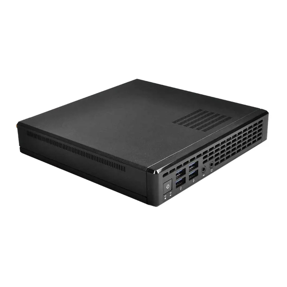
Chapter 2 Product Overview This chapter provides diagrams showing the location of important components of the Jupiter-H110. 2.1 Front View Headphone Microphone Jack Power button USB 3.1 Gen1 Ports... -
Page 11: Rear View
Jupiter-H110 2.2 Rear View Antenna Port Kensington Lock COM Port DisplayPort Audio Line-Out HDMI D-SUB Power Input USB 2.0 Ports LAN port * There are two LEDs on the LAN port. Please refer to the table below for the LAN port LED indications. -
Page 12: Chapter 3 Hardware Installation
Chapter 3 Hardware Installation This chapter helps you install or remove important components. 3.1 How to Install M.2 SSD 1. Carefully insert the SSD into the slot. 2. Tighten the screw to secure the SSD to the motherboard. -
Page 13: How To Safely Remove The Wireless Module
Jupiter-H110 3.2 How to Safely Remove the Wireless Module 1. Remove the screw of WLAN card. 2. Remove the WLAN card. 3. Disconnect the two antennas by manually lifting off the clips that hold them in place. -
Page 14: How To Install The Dram
3.3 How to Install the DRAM 1. The Jupiter-H110 requires DDR4 SO-DIMM. 2. For dual channel configuration, you always need to install identical (the same brand, speed, size and chip-type) DDR4 SO-DIMM pairs. The SO-DIMM only fits in one correct orientation. It will cause permanent damage to the motherboard and the DIMM if you force the DIMM into the slot at incorrect orientation. -
Page 15: How To Install The Heat Sink And Fan
Jupiter-H110 3.4 How to Install the Heat Sink and Fan 1. Carefully insert thermal modules. 2. Tighten the screw to secure the heatsink to the motherboard. 3. Carefully place the thermal module. Then connect the cable routing. Connect the cable... -
Page 16: How To Install The 2.5-Inch Hard Drive
3.5 How to Install the 2.5-inch Hard Drive 1. Remove the four screws on the bottom case. Then lift up and remove the bottom panel. 2. Pull the release lever out. Place the 2.5” hard drive into the bracket HDD. Then slide the 2.5”... -
Page 17: How To Secure The Chassis
Jupiter-H110 3.6 How to Secure the Chassis 1. Tighten the two knurled thumb screws to secure the chassis. -
Page 18: How To Install The Vesa Bracket
3.7 How to Install the VESA Bracket 1. Attach the VESA mount plate to the rear of a compatible display using the screws provided. 2. A. Jupiter can now be mounted by sliding the device into place. B. Assemble Jupiter to Vesa Mount with M2.5 screws... -
Page 19: Chapter 4 Software And Utilities Operation
Jupiter-H110 Chapter 4 Software and Utilities Operation 4.1 Installing Drivers The Support CD that comes with the motherboard contains necessary drivers and useful utilities that enhance the motherboard’s features. Running The Support CD To begin using the support CD, insert the CD into your CD-ROM drive. The CD automatically displays the Main Menu if “AUTORUN”... -
Page 20: Chapter 5 Uefi Setup Utility
Chapter 5 UEFI SETUP UTILITY 5.1 Introduction This section explains how to use the UEFI SETUP UTILITY to configure your system. You may run the UEFI SETUP UTILITY by pressing <F2> or <Del> right after you power on the computer, otherwise, the Power-On-Self-Test (POST) will continue with its test routines. -
Page 21: Navigation Keys
Jupiter-H110 5.1.2 Navigation Keys Use < > key or < > key to choose among the selections on the menu bar, and use < > key or < > key to move the cursor up or down to select items, then press <Enter>... -
Page 22: Main Screen
5.2 Main Screen When you enter the UEFI SETUP UTILITY, the Main screen will appear and display the system overview. -
Page 23: Advanced Screen
Jupiter-H110 5.3 Advanced Screen In this section, you may set the configurations for the following items: CPU Configuration, SATA Configuration, Configuration, Hardware Health Configu- ration, Onboard Devices Configuration, Trusted Computing and ME Subsystem. Setting wrong values in this section may cause the system to malfunction. -
Page 24: Cpu Configuration
5.3.1 CPU Configuration Virtualization Tech When this option is set to [Enabled], a VMM (Virtual Machine Architecture) can utilize the additional hardware capabilities provided by Vanderpool Technology. This option will be hidden if the installed CPU does not support Intel Virtualization Technology. - Page 25 Jupiter-H110 CPU C7 State report Enable/Disable CPU C7 state report to OS.
-
Page 26: Sata Configuration
5.3.2 SATA Configuration SATA Controller Enable/disable the SATA controller. SATA Controller Mode Selection AHCI: Supports new features that improve performance. AHCI (Advanced Host Controller Interface) supports NCQ and other new features that will improve SATA disk performance but IDE mode does not have these advantages. -
Page 27: Usb Configuration
Jupiter-H110 5.3.3 USB Configuration USB Controller Use this item to enable or disable the use of USB controller. -
Page 28: Hardware Health Configuration
5.3.4 Hardware Health Configuration In this section, it allows you to monitor the status of the hardware on your system, including the parameters of the CPU temperature, motherboard temperature, CPU fan speed, chassis fan speed, and the critical voltage. CPU Fan Fail Warning Enable/disable to detect Fan fault. -
Page 29: Onboard Devices Settings
Jupiter-H110 5.3.5 Onboard Devices Settings Configure onboard Devices. onboard VGA Config Configure onboard VGA Device. Onboard Audio Enable/disable onboard audio. Onboard LAN Device Enable/disable the onboard LAN device. Network stack Enable/disable the network stack. Serial Port 1 Configuration Use this item to configure the onboard serial port 1. - Page 30 Change Setting Select the device mode according to your connected device.
-
Page 31: Trusted Computing
Jupiter-H110 5.3.6 Trusted Computing TPM Supported This function enables or disables BIOS support for security device. O.S. will not show Security Device. TCG EFI protocol and INT1A interface will not be available. TPM Device Selection Use this item to select TPM device. -
Page 32: Me Subsystem
5.3.7 ME Subsystem ME Subsystem screen displays the Intel ME Subsystem Configuration information, such as Operational Firmware Version and Firmware State. -
Page 33: Power
Jupiter-H110 5.4 Power APM Configuration Configure Wake on Devices Settings. -
Page 34: Security Screen
5.5 Security Screen In this section you may set or change the supervisor/user password for the system. You may also clear the user password. Supervisor Password Set or change the password for the administrator account. Only the administrator has authority to change the settings in the UEFI Setup Utility. Leave it blank and press enter to remove the password. -
Page 35: Boot Screen
Jupiter-H110 5.6 Boot Screen This section displays the available devices on your system for you to configure the boot settings and the boot priority. Boot Settings Configuration Configure settings during the system boot. Launch CSM (Compatibility Support Module) Enable to launch the Compatibility Support Module. Please do not disable unless you’re running a WHCK test. -
Page 36: Exit Screen
5.7 Exit Screen Save Changes and Exit When you select this option the following message, “Save configuration changes and exit setup?” will pop out. Select [OK] to save changes and exit the UEFI SETUP UTILITY. Discard Changes and Exit When you select this option the following message, “Discard changes and exit setup?”...