Table of Contents
Advertisement
Hi-Fi A85W/Hi-Fi A75W Setup Manual
FCC Information and Copyright
This equipment has been tested and found to comply with the limits of a Class
B digital device, pursuant to Part 15 of the FCC Rules. These limits are designed
to provide reasonable protection against harmful interference in a residential
installation. This equipment generates, uses, and can radiate radio frequency
energy and, if not installed and used in accordance with the instructions, may
cause harmful interference to radio communications. There is no guarantee
that interference will not occur in a particular installation.
The vendor makes no representations or warranties with respect to the
contents here and specially disclaims any implied warranties of merchantability
or fitness for any purpose. Further the vendor reserves the right to revise this
publication and to make changes to the contents here without obligation to
notify any party beforehand.
Duplication of this publication, in part or in whole, is not allowed without first
obtaining the vendor's approval in writing.
The content of this user's manual is subject to be changed without notice and
we will not be responsible for any mistakes found in this user's manual. All the
brand and product names are trademarks of their respective companies.
Dichiarazione di conformità
sintetica
Ai sensi dell'art. 2 comma 3 del D.M.
275 del 30/10/2002
Si dichiara che questo prodotto è
conforme alle normative vigenti e
soddisfa i requisiti essenziali richiesti
dalle direttive
2004/108/CE, 2006/95/CE e
1999/05/CE
quando ad esso applicabili
Short Declaration of conformity
We declare this product is complying
with the laws in force and meeting all
the essential requirements as specified
by the directives
2004/108/CE, 2006/95/CE and
1999/05/CE
whenever these laws may be applied
Advertisement
Table of Contents

Related Manuals for Biostar Hi-Fi A85W


Summary of Contents for Biostar Hi-Fi A85W
- Page 1 Hi-Fi A85W/Hi-Fi A75W Setup Manual FCC Information and Copyright This equipment has been tested and found to comply with the limits of a Class B digital device, pursuant to Part 15 of the FCC Rules. These limits are designed to provide reasonable protection against harmful interference in a residential installation.
-
Page 2: Table Of Contents
Table of Contents Chapter 1: Introduction ..........1 Before You Start ................1 Package Checklist................1 Motherboard Features..............2 Rear Panel Connectors ..............3 Motherboard Layout ................4 Chapter 2: Hardware Installation ........5 Installing Central Processing Unit (CPU)........5 FAN Headers..................7 Installing System Memory ..............8 Connectors and Slots ...............10 Chapter 3: Headers &... -
Page 3: Chapter 1: Introduction
Hi-Fi A85W/Hi-Fi A75W CHAPTER 1: INTRODUCTION EFORE TART Thank you for choosing our product. Before you start installing the motherboard, please make sure you follow the instructions below: Prepare a dry and stable working environment with sufficient lighting. Always disconnect the computer from power outlet before operation. -
Page 4: Motherboard Features
10/ 100/ 1000 Mb/s auto negotiation, Half / Full duplex capability ALC892 Audio Codec 7.1 Channels, High Definition Audio, Biostar Hi-Fi 4x USB 3.0 port (2 on rear I/Os and 2 via internal headers) 8x USB 2.0 port (4 on rear I/Os and 4 via internal headers) -
Page 5: Rear Panel Connectors
Form Factor ATX Form Factor, 305mm x 235 mm Windows XP / Vista / 7/ 8 OS Support Biostar reserves the right to add or remove support for any OS with or without notice. ANEL ONNECTORS Note 1: HDMI / DVI-D / VGA Output require an AMD family processor with intedrated graphics. -
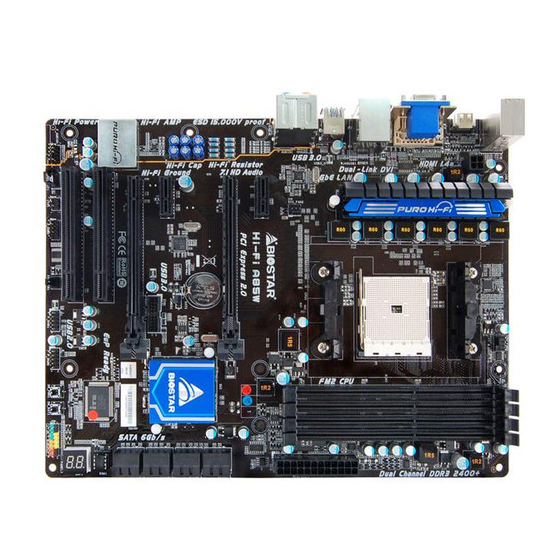
Page 6: Motherboard Layout
Motherboard Manual OTHERBOARD AYOUT Note: ■ represents the 1 pin. -
Page 7: Chapter 2: Hardware Installation
Hi-Fi A85W/Hi-Fi A75W CHAPTER 2: HARDWARE INSTALLATION (CPU) NSTALLING ENTRAL ROCESSING Step 1: Pull the socket locking out from the socket and then raise the lever up to a 90-degree angel. Step 2: Look for the white triangle on socket, and the gold triangle on CPU should point towards this white triangle. - Page 8 Motherboard Manual Step 3: Hold the CPU down firmly, and then close the lever to locked the position Step 4: Put the CPU Fan on the CPU and buckle it. Connect the CPU FAN power cable to the CPU_FAN1. This completes the installation.
-
Page 9: Fan Headers
Hi-Fi A85W/Hi-Fi A75W FAN H EADERS These fan headers support cooling-fans built in the computer. The fan cable and connector may be different according to the fan manufacturer. Connect the fan cable to the connector while matching the black wire to pin#1. -
Page 10: Installing System Memory
Motherboard Manual NSTALLING YSTEM EMORY A. DDR3 Modules Unlock a DIMM slot by pressing the retaining clips outward. Align a DIMM on the slot such that the notch on the DIMM matches the break on the slot. - Page 11 Hi-Fi A85W/Hi-Fi A75W Insert the DIMM vertically and firmly into the slot until the retaining chip snap back in place and the DIMM is properly seated. Note: If the DIMM does not go in smoothly, do not force it. Pull it all the way out and try again.
-
Page 12: Connectors And Slots
Motherboard Manual 2.4 C ONNECTORS AND LOTS ATXPWR1: ATX Power Source Connector This connector allows user to connect 24-pin power connector on the ATX power supply. Assignment Assignment +3.3V +3.3V -12V +3.3V Ground Ground PS_ON Ground Ground Ground Ground Ground PW_OK Standby Voltage+5V +12V... - Page 13 Hi-Fi A85W/Hi-Fi A75W PEX1_1/1_2: PCI-Express Gen2 x1 Slot PCI-Express 2.0 compliant. Data transfer bandwidth up to 500MB/s per direction; 1GB/s in total PCI1/2: Peripheral Component Interconnect Slot This motherboard is equipped with 2 standard PCI slots. PCI stands for Peripheral Component Interconnect, and it is a bus standard for expansion cards.
- Page 14 Motherboard Manual SATA1~SATA4: Serial ATA Connectors These connectors connect to SATA hard disk drives via SATA cables. Hi-Fi A85W supports 8 SATA 3.0 connectors. Hi-Fi A75W supports 6 SATA 3.0 connectors. Assignment Ground Ground Ground...
-
Page 15: Chapter 3: Headers & Jumpers Setup
Hi-Fi A85W/Hi-Fi A75W CHAPTER 3: HEADERS & JUMPERS SETUP OW TO ETUP UMPERS The illustration shows how to set up jumpers. When the jumper cap is placed on pins, the jumper is “close”, if not, that means the jumper is “open”. - Page 16 Motherboard Manual JFRONT_USB3_1: Header for USB 3.0 Ports at Front Panel This header allows user to connect additional USB cable on the PC front panel, and also can be connected with a wide range of simultaneously accessible external Plug and Play peripherals. Assignment Assignment VBUS0...
- Page 17 Hi-Fi A85W/Hi-Fi A75W F_AUDIO1: Front Panel Audio Header This header allows user to connect the front audio output cable with the PC front panel. This header supports HD and AC’97 audio front panel connector. HD Audio AC’97 Assignment Assignment Mic Left in...
- Page 18 Motherboard Manual JCMOS1: Clear CMOS Header Placing the jumper on pin2-3, it allows user to restore the BIOS safe setting and the CMOS data. Please carefully follow the procedures to avoid damaging the motherboard. Pin 1-2 Close: Normal Operation (default). Pin 2-3 Close: Clear CMOS data.
- Page 19 Hi-Fi A85W/Hi-Fi A75W CIR1: Consumer IR Connector This header is for infrared remote control and communication. Assignment IrDA serial input Ground Ground IrDA serial output IR Power On-Board Buttons There are 2 on-board buttons. SW_PWR1: This is an on-board Power Switch button.
-
Page 20: Chapter 4: Amd Dual Graphics Technology
Motherboard Manual CHAPTER 4: AMD DUAL GRAPHICS TECHNOLOGY AMD D RAPHICS ECHNOLOGY NTRODUCTION When user adds a PCIE display adapter, it can be integrated with IGD to show better performance. To make the two video devices work simultaneously and normally, please refer to the following setting. AMD D RAPHICS EQUIREMENT... -
Page 21: Amd Dual Graphics Setup
Hi-Fi A85W/Hi-Fi A75W AMD D RAPHICS ETUP Step 1: Insert Dual Graphics-Ready graphics card into PEX16_1 slot. Step 2: Set the BIOS setting as follows: [Chipset]→[North Bridge]→[Surround View]→[Enabled] Step 3: Install Driver DVD Chipset Driver, and reboot the system. Activate AMD VISION Engine Control Center to make sure CrossFire has been enabled. -
Page 22: Chapter 5: Raid Functions
Motherboard Manual CHAPTER 5: RAID FUNCTIONS PERATING YSTEM Supports Windows Vista, Windows 7 and Windows 8. RRAYS RAID supports the following types of RAID arrays: RAID 0: RAID 0 defines a disk striping scheme that improves disk read and write times for many applications. - Page 23 Hi-Fi A85W/Hi-Fi A75W RAID 1: Every read and write is actually carried out in parallel across 2 disk drives in a RAID 1 array system. The mirrored (backup) copy of the data can reside on the same disk or on a second redundant drive in the array. RAID 1 provides a hot-standby copy of data if the active volume or drive is corrupted or becomes unavailable because of a hardware failure.
- Page 24 Motherboard Manual RAID 10: RAID 1 drives can be stripped using RAID 0 techniques.Resulting in a RAID 10 solution for improved resiliency, performance and rebuild performance. Features and Benefits Drives: Minimum 4, and maximum is 6 or 8, depending on the platform. ...
- Page 25 Hi-Fi A85W/Hi-Fi A75W RAID 5: RAID 5 stripes both data and parity information across three or more drives. It writes data and parity blocks across all the drives in the array. Fault tolerance is maintained by ensuring that the parity information for any given block of data is placed on a different drive from those used to store the data itself.
-
Page 26: Chapter 6: Uefi Bios & Software
Motherboard Manual CHAPTER 6: UEFI BIOS & SOFTWARE UEFI BIOS UEFI BIOS Features Overclocking Navigator Engine (O.N.E.) Self Recovery System (S.R.S) Smart Fan Function BIO-Flasher: Update UEFI BIOS file from USB Flash Drive !! WARNING !! For better system performance, the UEFI BIOS firmware is being continuously updated. - Page 27 Hi-Fi A85W/Hi-Fi A75W Note: Overclock is an optional process, but not a “must-do” process; it is not recommended for inexperienced users. Therefore, we will not be responsible for any hardware damage which may be caused by overclocking. We also would not guarantee any overclocking performance.
- Page 28 Motherboard Manual CPU Smart FAN This item allows you to control the CPU Smart Fan function. CPU FAN Calibrate Press [ENTER] to calibrate CPU FAN. Control Mode This item provides several operation modes of the fan. Fan Ctrl OFF(℃) When CPU temperature is lower than this value, the CPU fan will keep lowest RPM.
-
Page 29: Software
Hi-Fi A85W/Hi-Fi A75W OFTWARE Installing Software 1. Insert the Setup DVD to the optical drive. The driver installation program would appear if the Auto-run function has been enabled. 2. Select Software Installation, and then click on the respective software title. - Page 30 Motherboard Manual The CPU tab provides information on the CPU and motherboard. The Memory tab provides information on the memory module(s). You can select memory module on a specific slot to see its information. The OC Tweaker tab allows you to change system clock settings and voltages settings.
- Page 31 Hi-Fi A85W/Hi-Fi A75W Six Pre-set Modes: V3, V6, V9, V12, V15, AUTO for different overclocking experience. (The screenshot below is for reference only) The HW Monitor tab allows you to monitor hardware voltage, fan speed, and temperature. Besides, you also can set related values for CPU Smart Fan.
- Page 32 “Live Update.” Green Power II Utility BIOSTAR G.P.U II (Green Power Utility) is a new function. The utility enhances energy efficiency by disabling extra phases while CPU is on light loading; it features 4+1 power phases, current power saving, and toal power saving. This tool integrates a friendly GUI to monitor your CPU Usage, CPU Watt, and CPU Temperature.
- Page 33 Hi-Fi A85W/Hi-Fi A75W G.P.U Mode Setting This utility provides five modes, upon your requirements, to improve system performance or to save power consumption. Note: Even if the modes saving more power consumption are chosen, the system still can keep excellent performance.
- Page 34 Exit Button: Exit the application Note: 1. Smart EAR is only supported by Windows 7 and BIOSTAR Hi-Fi series motherboards. 2. High/Low Gain Switch is only for “Front Panel Audio Header”, please make sure you are connecting your headphone to the front panel I/O.
- Page 35 Hi-Fi A85W/Hi-Fi A75W eHot-Line (Optional) eHot-Line is a convenient utility that helps you to contact with our Tech-Support system. This utility will collect the system information which is useful for analyzing the problem you may have encountered, and then send these information to our tech-support department to help you fix the problem.
- Page 36 If you are not using Outlook Express as your default e-mail client application, you may need to save the system information to a .txt file and send the file to our tech support with other e-mail application. Go to the following web http://www.biostar.com.tw/app/en/about/contact.php for getting our contact information.
- Page 37 Hi-Fi A85W/Hi-Fi A75W BIOScreen Utility (Optional) This utility allows you to personalize your boot logo easily. You can choose BMP as your boot logo so as to customize your computer. Please follow the following instructions to update boot logo: 1. Load Image:Choose the picture as the boot logo.
-
Page 38: Bios Update
BIOS Update Utility, BIOS Online Update Utility and BIOS Flasher. 1. BIOS Update Utility 1. Installing BIOS Update Utility from the DVD Driver. Download the proper BIOS from www.biostar.com.tw 3. Open BIOS Update Utility and click the Update BIOS button on the main screen. - Page 39 Hi-Fi A85W/Hi-Fi A75W 7. While the system boots up and the full screen logo shows up, please press <Delete> key to enter BIOS setup. After entering the BIOS setup, please go to the Save & Exit, using the Restore Defaults function to load Optimized Defaults, and select Save Changes and Reset to restart the computer.
- Page 40 Motherboard Manual 5. If there is a new BIOS version, the utility will ask you to download it. Click Yes to proceed. 6. After the download is completed, you will be asked to program (update) the BIOS or not. Click Yes to proceed. 7.
- Page 41 Shutting down or resetting the system while updating the BIOS will lead to system boot failure. The BIOSTAR BIOS Flasher is built in the BIOS ROM. To enter the utility, press <F12> during the Power-On Self Tests (POST) procedure while booting up.
- Page 42 Motherboard Manual 7. A dialog pops out after BIOS flash is completed, asking you to restart the system. Press the [Y] key to restart system. 8. While the system boots up and the full screen logo shows up, press <Delete> key to enter BIOS setup. After entering the BIOS setup, please go to the Save &...
-
Page 43: Chapter 7: Useful Help
Hi-Fi A85W/Hi-Fi A75W CHAPTER 7: USEFUL HELP RIVER NSTALLATION After you installed your operating system, please insert the Fully Setup Driver DVD into your optical drive and install the driver for better system performance. You will see the following window after you insert the DVD The setup guide will auto detect your motherboard and operating system. -
Page 44: Extra Information
Motherboard Manual XTRA NFORMATION CPU Overheated If the system shutdown automatically after power on system for seconds, that means the CPU protection function has been activated. When the CPU is over heated, the motherboard will shutdown automatically to avoid a damage of the CPU, and the system may not power on again. -
Page 45: Ami Bios Beep Code
Hi-Fi A85W/Hi-Fi A75W AMI BIOS B Boot Block Beep Codes Number of Beeps Description Continuing Memory sizing error or Memory module not found POST BIOS Beep Codes Number of Beeps Description Success booting. Display memory error (system video adapter) AMI BIOS P... - Page 46 Motherboard Manual Code Description North Bridge DXE SMM initialization is started South Bridge DXE initialization is started South Bridge DXE SMM initialization is started South Bridge devices initialization South Bridge DXE Initialization (South Bridge module specific) ACPI module initialization Boot Device Selection (BDS) phase is started Driver connecting is started PCI Bus initialization is started PCI Bus Hot Plug Controller Initialization...
-
Page 47: Troubleshooting
Hi-Fi A85W/Hi-Fi A75W ROUBLESHOOTING Probable Solution There is no power in the system. Make sure power cable is Power LED does not shine; the securely plugged in. fan of the power supply does not Replace cable. work Contact technical support. -
Page 48: Appendix: Spec In Other Languages
– اﻟﺤﺪ اﻷﻗﺼﻰ ﻟﻠﻄﺎﻗﺔ اﻟﺤﺮارﻳﺔ ﻓﻲ ﺗﺼﻤﻴﻢ اﻟﻤﻌﺎﻟﺞ ﻗﺎﻋﺪة وﺣﺪة اﻟﻤﻌﺎﻟﺠﺔ اﻟﻤﺮآﺰﻳﺔ ﻟﻘﺎﺋﻤﺔ دﻋﻢ اﻟﻤﻌﺎﻟﺞ www.biostar.com.tw ﻳﺮﺟﻰ اﻟﺮﺟﻮع إﻟﻰ اﻟﻤﻮﻗﻊ (Hi-Fi A75W) FCH A75 اﻳﻪ إم دى (Hi-Fi A85W) اﻳﻪ إم دى ﻣﺠﻤﻮﻋﺔ اﻟﺸﺮاﺋﺢ 2133 1866 1600 1333 1066 DDR3 . - Page 49 Hi-Fi A85W/Hi-Fi A75W اﻟﻤﻮاﺻﻔﺎت SATA SATA اﻟﺜﺎﻧﻴﺔ ﺟﻴﺠﺎﺑﺎﻳﺖ وﺻﻠﺔ اﻟﺜﺎﻧﻴﺔ ﺟﻴﺠﺎﺑﺎﻳﺖ وﺻﻠﺔ آﻞ ﻣﻮزع ﻳﺘﺤﻤﻞ ﺎم ﻧﺎﻗﻞ ﻣﺘﺴﻠﺴﻞ ﻋ ﻣﻮزع آﻞ ﻣﻮزع ﻧﺎﻗﻞ ﻣﺘﺴﻠﺴﻞ ﻋﺎم ﻣﻮزع ﻓﺘﺤﺘﻴﻦ ﻧﺎﻗﻞ ﻣﺘﺴﻠﺴﻞ ﻋﺎم ﻳﺘﺤﻤﻞ ﻓﺘﺤﺘﻴﻦ ﻧﺎﻗﻞ ﻣﺘﺴﻠﺴﻞ ﻋﺎم آﻞ ﻣﻮزع ﻳﺘﺤﻤﻞ ﻧﺎﻗﻞ ﻣﺘﺴﻠﺴﻞ ﻋﺎم...
-
Page 50: French
ALC892 Codec audio Canaux 7.1, écoute audio de haute définition, Biostar Hi-Fi Port 4x USB 3.0 (2 sur les I/O arrières et 2 en interne) Port 8x USB 2.0 (4 sur les I/O arrières et 4 en interne) - Page 51 1x Connecteur sortie S/PDIF 1x Connecteur sortie S/PDIF Facteur Facteur d'encombrement ATX, 305mm x 235 mm d'encombrement Windows XP / Vista / 7/ 8 Support SE Biostar se réserve le droit d’ajouter ou d'enlever le support pour toute SE avec ou sans préavis.
-
Page 52: German
Maximale CPU TDP (Thermal Design Power): 100 Watt www.biostar.com.tw * Bitte konsultieren Sie für CPU-Unterstützungsliste Chipset AMD A85 FCH (Hi-Fi A85W) AMD A75 FCH (Hi-Fi A75W) Unterstützt zweikanaliges DDR3 800/ 1066/ 1333/ 1600/ 1866/ 2133(OC) 4 x DDR3 DIMM-SpeicherSlot, Max. Uterstützung bis zu 64 GB-Speicher Festplattenspeicher Jedes DIMM unterstützt nicht-ECC 512MB/ 1/ 2/ 4/ 8/ 16 GB DDR3-Module... - Page 53 1x Serieller Port-Header 1x Serieller Port-Header 1x S/PDI-Auswurfsverbindung 1x S/PDI-Auswurfsverbindung Formfaktor ATX Formfaktor, 305mm x 235 mm Windows XP / Vista / 7/ 8 OS-Unterstützung Biostar reserves the right to add or remove support for any OS with or without notice.
-
Page 54: Italian
10/ 100/ 1000 Mb auto negoziazione, capacita di duplex Meta / Completo ALC892 Codec Audio Canali Audio di Alta Definizione 7.1, Biostar Hi-Fi Slot 4x USB 3.0 (2 nei ingressi/ uscite posteriore e 2 da distributori interni) Slot 8x USB 2.0 (4 nei ingressi/ uscite posteriore e 4 da distributori interni) - Page 55 Connettore esterno S/PDIF x1 Fattore di Forma Fattore di Forma ATX, 305mm x 235 mm Windows XP / Vista / 7/ 8 Supporto SO Biostar si riserva il diritto di aggiungere o ritirare il supporto per qualsiasi SO con o senza preavviso.
-
Page 56: Japanese
Realtek RTL 8111F 10/ 100/ 1000 Mb/s オートネゴーシエーション、半/全 二重通信 ALC892 オーディオ コーデッ 7.1 チャンネル, ハイ デフィニション オーディオ, Biostar Hi-Fi ク 4x USB 3.0 ポート (後部 I/O に2つ 及び 内蔵 ヘッダー経由に2つ) 8x USB 2.0 ポート (後部 I/O に4つ 及び 内蔵ヘッダー経由に4つ) 2x PCI スロット... - Page 57 Hi-Fi A85W/Hi-Fi A75W 仕様 Hi-Fi A85W: Hi-Fi A75W: 8x SATA 6.0Gb/s コネクタ 6x SATA 6.0Gb/s コネクタ 2x USB 2.0 ヘッダー (各ヘッダーは、2つの 2x USB 2.0 ヘッダー (各ヘッダーは、2つの USB 2.0 ポートをサポートしています) USB 2.0 ポートをサポートしています) 1x USB 3.0 ヘッダー (各ヘッダーは、2つの 1x USB 3.0 ヘッダー (各ヘッダーは、2つの...
-
Page 58: Polish
ALC892 Codec Audio Kanały Audio wysokiej Definicji 7.1, Biostar Hi-Fi 4 x złącza USB 3.0 (2 przez tylne porty wejścia/ wyjścia oraz 2 przez wewnętrzne porty) 8 x złącza USB 2.0 (4 przez tylne porty wejścia/ wyjścia oraz 4 przez wewnętrzne porty) złącza 2x PCI (Slot) - Page 59 Port zewnętrzny S/PDIF x1 Port zewnętrzny S/PDIF x1 Obudowa Obudowa ATX, 305mm x 235 mm Windows XP / Vista / 7/ 8 Obsługa OS Biostar zastrzega sobie prawo do dodania lub wycofania obsługi dla OS, z wypowiedzeniem lub bez wypowiedzenia.
-
Page 60: Portuguese
10/ 100/ 1000 Mb auto negociação, capacidade duplex Metade / Cheio ALC892 Codec de Audio Canais de Áudio de Alta Definição 7.1, Biostar Hi-Fi Porta 4x USB 3.0 (2 nas entradas/saídas traseiras e 2 pelos Dispositivos internos) Porta 8x USB 2.0 (4 nas entradas/saídas traseiras e 4 pelos Dispositivos internos) Porta 2x PCI Slots de expansão... - Page 61 Conector Externo S/PDIF x1 Fator de Fôrma Fator de Fôrma ATX, 305mm x 235 mm Windows XP / Vista / 7/ 8 Suporte OS Biostar reserva seu direito de adicionar ou retirar o suporte para qualquer OS com ou sem notificação.
-
Page 62: Russian
* Перечень поддержки центрального процессора смотрите на процессора www.biostar.com.tw Набор микросхем AMD A85 FCH (Hi-Fi A85W) AMD A75 FCH (Hi-Fi A75W) Поддерживает двухканальный DDR3 800/ 1066/ 1333/ 1600/ 1866/ 2133(OC) 4 гнезда платы памяти DDR3 DIMM, максимальная память до 64 Гб... - Page 63 1 контакт последовательного порта 1 соединитель S/PDIF-Out 1 соединитель S/PDIF-Out Конструктив Форм-фактор ATX, 305мм x 235 мм Windows XP / Vista / 7/ 8 Поддержка ОС Biostar оставляет за собой право добавлять или удалять поддержку любой ОС, с уведомлением или без.
-
Page 64: Spanish
10/ 100/ 1000 Mb/s auto negociación, capacidad dúplex Mitad/Completo ALC892 Códec Audio Canales Audio de Alta Definición 7.1, Biostar Hi-Fi Ranura 4x USB 3.0 (2 en las entrada/salidas posteriores y 2 por los distribuidores internos) Ranura 8x USB 2.0 (4 en las entrada/salidas posteriores y 4 por los distribuidores... - Page 65 Conector Externo S/PDIF x1 Factor de Forma Factor de Forma ATX, 305mm x 235 mm Windows XP / Vista / 7/ 8 Soporte OS Biostar reserva su derecho de añadir o retirar el soporte para cada OS con o sin notificación. 2013/04/23...