Table of Contents
Advertisement
Quick Links
Safe Operation Practices • Set-Up • Operation • Maintenance • Service • Troubleshooting • Warranty
O
'
M
peratOr
s
anual
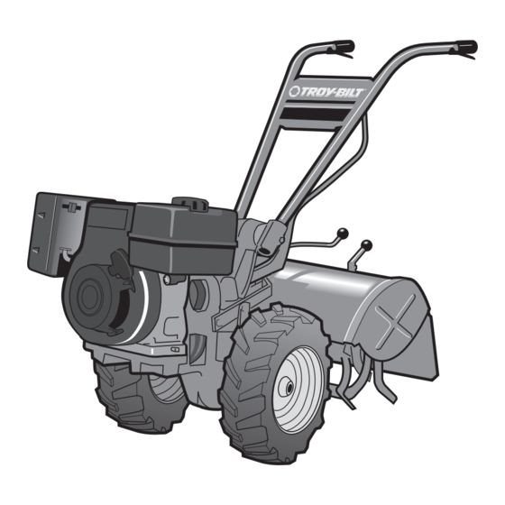
Rear-Tine Tiller — Model 682
WARNING
READ AND FOLLOW ALL SAFETY RULES AND INSTRUCTIONS IN THIS MANUAL
BEFORE ATTEMPTING TO OPERATE THIS MACHINE.
FAILURE TO COMPLY WITH THESE INSTRUCTIONS MAY RESULT IN PERSONAL INJURY.
TROY-BILT LLC, P.O. BOX 361131 CLEVELAND, OHIO 44136-0019
Printed In USA
Form No. 769-03557
(November 6, 2007)
Advertisement
Table of Contents

Related Manuals for Troy-Bilt 682


Summary of Contents for Troy-Bilt 682
- Page 1 READ AND FOLLOW ALL SAFETY RULES AND INSTRUCTIONS IN THIS MANUAL BEFORE ATTEMPTING TO OPERATE THIS MACHINE. FAILURE TO COMPLY WITH THESE INSTRUCTIONS MAY RESULT IN PERSONAL INJURY. TROY-BILT LLC, P.O. BOX 361131 CLEVELAND, OHIO 44136-0019 Printed In USA Form No. 769-03557...
-
Page 2: Table Of Contents
Call a Customer Support Representative at (800) 828-5500 or (330) 558-7220 ◊ Write us at Troy-Bilt LLC • P.O. Box 361131 • Cleveland, OH • 44136-0019 This product has met the rigid safety standards of the Outdoor Power Equipment Institute and an independent testing laboratory. -
Page 3: Safe Operation Practices
Important Safe Operation Practices WARNING! This symbol points out important safety instructions which, if not followed, could endanger the personal safety and/or property of yourself and others. Read and follow all instructions in this manual before attempting to operate this machine. Failure to comply with these instructions may result in personal injury. - Page 4 When practical, remove gas-powered equipment from the truck or trailer and refuel it on the ground. If this is not possible, then refuel such equipment on a trailer with a portable container, rather than from a gasoline dispenser nozzle. Keep the nozzle in contact with the rim of the fuel tank or container opening at all times until fueling is complete.
- Page 5 If the fuel tank has to be drained, do this outdoors. Observe proper disposal laws and regulations for gas, oil, etc. to protect the environment. Notice Regarding Emissions Engines which are certified to comply with California and federal EPA emission regulations for SORE (Small Off Road Equipment) are certified to operate on regular unleaded gasoline, and may include the following emission control systems: Engine Modification (EM) and Three Way Catalyst (TWC) if so equipped.
-
Page 6: Assembly & Set-Up
Assembly & Set-Up Contents of Carton • One Tiller • One Hardware Pack WARNING! To prevent personal injury or property damage, do not start the engine until all assembly steps are complete and you have read and understand the safety and operating instructions in this manual. - Page 7 Moving the Tiller off the Shipping Platform Set the Depth Regulator Lever to travel position. Do this by lifting the tiller by the handlebars, then pulling straight back on the lever and sliding down to the highest notched setting. See Fig. 3-2. Figure 3-2 Set the Wheel Speed Lever to the Freewheel position.
- Page 8 Wheels/Tines PTO Drive Lever Loosen the bolt on the handlebar base and swing the handlebars out to the right side. See Fig. 3-1. Remove both sets of nuts, star washers, screws, and one bushing from the yoke plates. See Fig. 3-6. There is a bushing inside the short link.
- Page 9 Pull the Wheels/Tines/PTO Lever back to align the forward most holes in the yoke plate with the holes in the lever plates. Also align the bushing that is inside the short link bar. Install the screw, star washer, and nut, then tighten securely.
- Page 10 Engine Throttle Lever and Cable For shipping purposes, the throttle cable, together with the throttle lever, is wound around the engine. Carefully unwind the cable. If the throttle control label is covered with a clear protective coating, peel it off. WARNING! To avoid electric shock from a short circuit (electric start tillers only), never allow the...
- Page 11 Use a 5⁄8” long screw and 1⁄4-20 hex nut to connect the positive (+) battery cable to the positive (+) battery post. Make sure that this is the cable on the left side, with one end attached to the solenoid. See Fig 3-14. WARNING! To Avoid Personal Injury or Property Damage: Do not touch the positive battery terminal...
-
Page 12: Controls & Features
Controls and Features Tines/PTO Clutch Lever Tiller controls and features are described below and illustrated in Fig. 4-1. WARNING! Be familiar with all the controls and their proper operation. Know how to stop the machine and disengage it quickly. NOTE: For detailed information on all engine controls refer to the seperate Engine Operator’s Manual. -
Page 13: Operation
Operation Starting the Engine The following steps describe how to start and stop the engine. NOTE: Do not attempt to engage the tines, wheels, or any PTO attachment until you have read all of the operating instructions in this section. Pre-Start Checklist Make the following checks and perform the following services before starting the engine. - Page 14 Starting Electric Start Engine with Recoil Starter You may, at some point, have to start an electric start engine with the recoil starter rope. Before attempting to do so, perform the following applicable steps: • If you suspect the battery charge is weak, and there is no visible damage.
- Page 15 When the tiller moves forward, relax and let the wheels power the tiller along while the tines dig. Walk behind and to one side of the tiller. Walk on the side that is not yet tilled. Use a firm grip on the handlebars but keep your arm relaxed.
- Page 16 Choosing Wheel & Tine Speeds The tiller has four FORWARD wheel/tine speed combinations for handling a variety of tilling tasks and gardening jobs. Experiment with the tine depth, engine speed, and wheel/tine speed to determine the combination that provides the best results. Here are some tips: Advance the throttle lever so the engine has sufficient power.
- Page 17 Changing Belt From Low Range to High Range To avoid personal injury, shut off the engine, let all moving parts come to a complete stop, then disconnect the spark plug wire from the spark plug and move the wire away from the spark plug before making any adjustments.
- Page 18 Stand on the left side of the tiller. Use your right hand to hold the Wheels/Tines/PTO Drive Lever up into REVERSE position. Use your left hand to move the belt off the top-front engine pulley groove to top-rear engine pulley groove.
- Page 19 Avoid Tilling Wet, Soggy Soil • Tilling wet soil often results in large, hard clumps of soil that can interfere with planting. If time permits, wait a day or two after heavy rains to allow the soil to dry before tilling. Test the soil by squeezing it into a ball. If it compresses too easily, it is too wet to till.
- Page 20 • With planning, you can allow enough room between rows to cultivate. Leave room for the hood width, plus enough extra room for future plant growth. See Fig. 4-14. Figure 4-14 Tilling on Slopes If you must garden on sloping ground, please follow two very important guidelines: Till only on moderate slopes, never on steep inclines where footing is difficult Review the safety rules in the Safe...
- Page 21 • Move the belt into LOW belt range and the Wheel Speed Gear Lever to SLOW position. As in terrace gardening, start at the top of the slope and overlap the first pass by half the width of the tiller. For added stability, keep the uphill wheel in the soft, newly tilled soil.
- Page 22 Tilling Under Corn After corn is harvested, the stalks should be tilled into the soil while still green. Dry plants are more difficult to till under, and the roots break loose too easily. NOTE: Do not pull the roots out by hand or cut the stalks before tilling.
- Page 23 Then move the swing-out bolts out. See Fig. 4-21. Swing-Out Bolt Figure 4-21 NOTE: Loosening swing-out bolts can be difficult. Use an extra-long wrench for leverage. Tip the PTO power machine forward about one inch with one hand while pulling the tine attachment back. Fig. 4-22. Guide Pin Mounting Hole Figure 4-22...
-
Page 24: Moving The Tiller
Moving the Tiller When the engine is running, the tiller’s powered wheels make moving the tiller to and from the garden easy. If the engine is not running, set the Wheel Speed Lever to FREEWHEEL position to roll the tiller to another location. WARNING! To help avoid personal injury from revolving tines, always put the Tines/PTO Clutch... -
Page 25: Maintenance & Adjustments
Maintenance & Adjustments Maintenance Schedule Check Engine Oil Level Clean Engine Cooling System Test Operation of FWD. Interlock Safety System FWD. Interlock Safety System — Check Wire Condition/Connections Check Electrical Connections Recharge Battery Check Drive Belt Tension Check Nuts and Bolts Clean Tiller Tine Shaft Lubricate Tiller Change Engine Oil... - Page 26 Tire Pressure Check the air pressure in both tires every 30 operating hours. Deflate or inflate both tires evenly to 15- to 20-PSI (pounds per square inch). Be sure that both tires have the same air pressure or the tiller will tend to pull to one side.
- Page 27 Rear Bearing Cap Screws • The three rear bearing cap screws are located under the depth regulator mounting bracket. If any are loose, it can cause an oil leak or drive shaft end play. See Fig. 6-3. Cap Screw Bolt Eccentric Lever Swing Bolt Lock Nut...
- Page 28 • If tilling during very hot weather, the gear oil may heat up and expand inside the transmissions. To allow for this oil expansion, both the power unit transmission and the tine attachment transmissions have oil relief vents. See Fig. 6-5. Oil Vents Figure 6-5 •...
- Page 29 For dipsticks With ‘Check Cold’ Marking (Cold means 2 hours have passed since the tiller was used.) Move the tiller to level ground. Pull the Depth Regulator Lever back, then push it down all the way (to engage its top notch). Place a sturdy support under the engine to prevent the tiller from tilting too far.
- Page 30 Using the 3⁄8” wrench, remove the drain plug. The gear oil will drain quite slowly since it is thick. After about two quarts have drained, tilt the tiller forward so any oil at the rear of the transmission will drain out. Clean the drain plug threads, put non-hardening gasket sealant on the threads, and reinstall the plug.
- Page 31 Lubricate the tiller as follows: Oil the wheel shaft between the wheel hubs and the transmission housing. See Fig. 6-10. Wheels/Tines/PTO Drive Lever Wheel Speed Lever Belt Adjustment Block Depth Grease Fitting Regulator Lever Figure 6-10 Oil all pivoting and connecting points on the Wheels/ Tines/PTO Drive Lever and the Wheel Speed Lever.
- Page 32 How to Measure the Belt Tension Before taking a measurement, be sure the linkages and pivot points on the Wheels/Tines/PTO Drive Lever are clean and lubricated. If there is any binding, you won’t get true measurements. Also, you’ll need the belt adjustment tool you received with your new tiller.
- Page 33 Insert the belt adjustment tool through the hole in the side of the adjustment block, spacing the ends of the tool equally on both sides. See Fig. 6-15. Rotate the tool so the slotted end faces down. Belt Adjustment Tool Figure 6-15 Place the Wheels/Tines/PTO Drive Lever in FORWARD position.
- Page 34 Measure the width of the outside edge of the disc as shown in Fig. 6-18. Replace the disc before the rubber edge wears to a thickness of 1⁄8” or less. Failure to do so could cause the steel underneath the rubber to damage the transmission pulley.
- Page 35 Use your left hand to hold the Wheels/Tines/PTO Drive Lever up in REVERSE, while briefly pulling out engine recoil starter. The reverse disc should turn the lower pulley. See Fig. 6-21. If not, or it requires a lot of pressure to hold the lever up in REVERSE, then the reverse adjustment bolt must be adjusted downward.
- Page 36 Move the Wheels/Tines/PTO Drive Lever to NEUTRAL. The switch body on the bottom of the engine mount tab should be resting squarely on top of the reverse adjustment bolt, and the reverse disc should be at least 3⁄16” away from the transmission drive pulley. See Fig. 6-19. If the reverse disc is any closer than this, raise the reverse adjustment bolt (turn it counterclockwise).
-
Page 37: Service
Service Belt Replacement Drive Belt Move the Wheels/Tines/PTO Drive Lever to NEUTRAL position. While kneeling on the right side of the tiller, create slack in the belt by reaching over to the left side of the pulleys and pushing in on the center of the belt with your finger. Use your right hand to move the belt down and away from the lower pulley, in the direction of the engine. - Page 38 Push the belt forward then down until it is looped over the lower pulley. See Fig. 7-2. Do not yet seat it in either of the lower pulley’s grooves. NOTE: A blunt object, like a ruler, can help you push the belt downward if needed.
- Page 39 If badly worn, they lose the ability to till deeply. Worn tines leave an ever-increasing gap in the middle of a tilled row. The normal gap is 3” between the tine tips — replace the tines when the gap widens to 5”. See Fig. 7-8. The tines can be replaced individually or as a complete set.
-
Page 40: Troubleshooting
Troubleshooting Problem Engine does not start Engine runs poorly or overheats Engine runs well, but labors under tillers load Engine shuts off when Wheels/Tines/PTO Drive Lever is in forward Cause Wheels/Tines/PTO Drive Lever not in Neutral position Fuel tank low or empty. Fuel line restricted or clogged. - Page 41 Problem Wheels and tines do not Misadjusted drive belt and/or reverse disc turn Loose bolt on transmission drive pulley Worn worm gears Wheels and tines turn on Loose drive belt top of ground, but stop or hesitate in soil Loose bolt on transmission drive pulley Wheels turn, but tines do Tines/PTO clutch lever not engage Tines/PTO clutch lever out of adjustment...
-
Page 42: Replacement Parts
Replacement Parts Component Phone (800) 800-7310 to order replacement parts or a complete Parts Manual (have your full model number and serial number ready). Parts Manual downloads are also available free of charge at www.mtdproducts.com. Part Number and Description GW-9245 V-Belt 742-04119 Bolo Tine (LH), 12”... - Page 43 Notes...
- Page 44 MANUFACTURER’S LIMITED WARRANTY FOR The limited warranty set forth below is given by Troy-Bilt LLC with respect to new merchandise purchased and used in the United States and/or its territories and possessions, and by MTD Products Limited with respect to new merchandise purchased and used in Canada and/or its territories and possessions (either entity respectively, “Troy-Bilt”).