Table of Contents
Advertisement
0 T- RnV BILT* - -
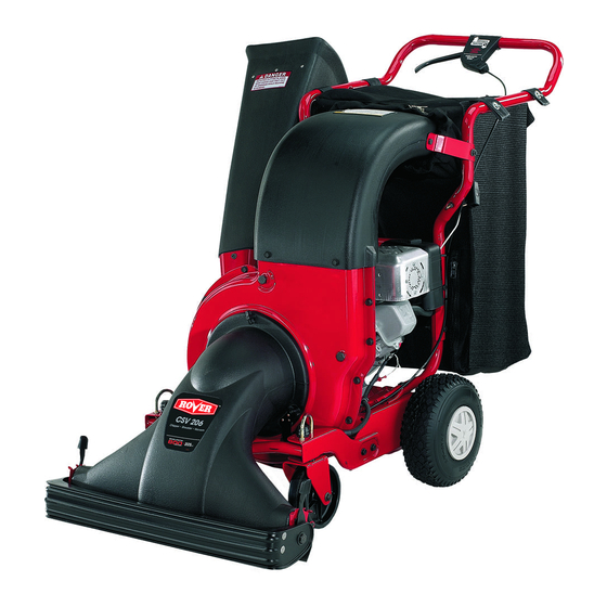
Operator's Manual
Chipper Shredder Vacuum
IMPORTANT:
Read safety rules and instructions
carefully
Warning:
This unit is equipped with an internal combustion engine and should not be used on or near any unimproved forest-covered,
brush-
covered or grass-covered
land unless the engine's exhaust system is equipped with a spark arrester meeting applicable
local or state laws (if
any). If a spark arrester is used, it should be maintained in effective working order by the operator. In the State of California the above is required
by law (Section 4442 of the California Public Resources Code). Other states may have similar laws. Federal laws apply on federal lands. A spark
arrester for the muffler is available through your nearest engine authorized service dealer or contact the service department,
P.O. Box 361131
Cleveland, Ohio 44136-0019.
TROY-BILT LLC P.O.BOX361131 CLEVELAND, OHIO44136-0019
PRINTED IN U.S.A.
FORM NO.
769-00170B
(11/2003)
Advertisement
Table of Contents

Related Manuals for Troy-Bilt CSV206


Summary of Contents for Troy-Bilt CSV206
- Page 1 (Section 4442 of the California Public Resources Code). Other states may have similar laws. Federal laws apply on federal lands. A spark arrester for the muffler is available through your nearest engine authorized service dealer or contact the service department, P.O. Box 361131 Cleveland, Ohio 44136-0019. TROY-BILT LLC P.O.BOX361131 CLEVELAND, OHIO44136-0019 PRINTED IN U.S.A. FORM NO. 769-00170B...
- Page 2 A sample model plate is explained below. For future reference, please copy the model number and the serial number of the equipment in the space below. Copy the model number here: Copy the serial number here: OT__H_T ° TROY-BILT P. O. BOX 361131 www.troybilt.com CLEVELAND, OH 44136...
- Page 3 SECTION 1: IMPORTANT SAFEOPERATION P RACTICES WARNING: This symbol points out important safety instructions which, if not followed, could endanger the personal safety and/or property of yourself and others. Read and follow all instructionsin this manual before attempting to operate this machine. Failure to comply with these instructions may result in personal injury.
- Page 4 2, Before s tarting themachine, make s ure thechipper stopped. Disconnect the spark plug wire and ground it chute, feed intake, and cutting chamber are empty and against the engine to prevent unintended starting, free of all debris, Do not change the engine governor settings or Thoroughly inspect all material to be shredded and overspeed the engine, The governor controls the remove any metal, rocks, bottles, cans, or other foreign...
- Page 5 SECTION 2: ASSEMBLING YOUR CHIPPER SHREDDER VACUUM Unpacking Attaching The Nozzle • Remove staples, break glue on top flaps, or cut • Remove three wing nuts from the front of the tape at carton end and peel along top flap to open chipper shredder vacuum.
- Page 6 Remove the three hex nuts and bell washers from Align the support bracket with the holes in the right the weld studs beside the opening on the right side side of the upper and lower handles where the hex of the chipper-shredder vacuum.
- Page 7 SECTION 3: KNOW YOUR CHIPPER SHREDDER V ACUUM ARNING: Be familiar with all controls and their proper operation. Know how to stop the machine and disengage them quickly. Drive Clutch Control Tamper Plug Chipper Chute Nozzle Nozzle Door Adjustment Lever Caster Locks Figure 7 Nozzle...
- Page 8 SECTION 4: OPERATING Y OUR CHIPPER SHREDDER V ACUUM Read, understand, and follow all instructions and • Repeat until engine cranks. When engine starts, warnings on the machine and in this manual before move choke control (if equipped) gradually to RUN operating.
- Page 9 SECTION 5: ADJUSTING YOUR CHIPPER SHREDDER V ACUUM Slide the height adjustment lever forward or backward for adjusting the nozzle door upwards or WARNING: Do not at time make downwards. Height must be adjusted equally. In adjustments without first stopping engine, disconnecting spark plug wire, and grounding it general, raise the nozzle to vacuum a thick layer of leaves and lower the nozzle for smooth surfaces.
- Page 10 SECTION 6: MAINTAINING YOUR CHIPPER SHREDDER V ACUUM • Reattach the discharge chute assembly with the hardware previously removed and attach the bag to WARNING: Before performing any the unit. maintenance or repairs, stop the engine, wait until the machine comes to a complete stop, Hex Bolts disconnect the spark plug wire and ground Hex Nuts...
- Page 11 Remove the two hex bolts and hex lock nuts which extend through the housing. Lift the flail screen out WARNING: Use caution when replacing the heavy gloves injury of the housing. Refer to Figure 11. blades. Wear to avoid while handling the weld bolts, housing or the blades.
- Page 12 Outer Mounting Belt Guard c_ Spring Housing_ Adapter Idler--_ _-__erke t Transmission Pulley Holes foi" Screwdrivers Figure 17 • Press down on the belt guard spring by the idler Figure 18 pulley, and release the spring from the slot on the idler bracket.
- Page 13 SECTION 7: TROUBLESHOOTING Problem Cause Remedy Engine fails to start Spark plug wire disconnected. Connect wire to spark plug. Fuel tank empty or stale fuel. Fill tank with clean, fresh gasoline. Throttle control lever not in correct Move throttle lever to FAST position. starting position.
- Page 14 SECTION 8: PARTS LISTFORMODEL 204 Ref. Part No. Description 781-0633 Chute Flap Strip 735-0249 Chute F!ap 728-0175 Pop Rivet 731-1838A Discharge Chute 764-04001 'Bag 631-0086 Nozzle Assembly 731-1831 Nozzle Flap 710-0969 Screw 720-0190 Height Adjustment Knob 732-0754 Ispring Lever 781-0702 Index Bracket RH 781-0703 'Index Bracket LH...
- Page 15 Model204 15 13 _P" 681-0108 Impeller Assembly: Complete 781-0599 Upper Shredder Blade 719-0329 Flail Blade 736-0119 Lock Washer 5/16 715-0166 Spiral Pin 710-0772 Hex Cap Screw 5/16-18 x 2 681-0107 'Impeller Assembly 781-0653 Flail Housing Blade 711-0833B Clevis Pin 710-3008 Hex Cap Screw 5116-18 x .75 736-0119 Lock Washer 5/16...
- Page 16 Model204 ..15 \\\\\ "53...
- Page 17 Model204 Ref. Ref. Part No. Description Part No. Description 741-0414 Flange Bearing .629 ID 781-0677 Chain Case LH 781-0676 Chain Case RH 741-0415 Flange Bearing .566 ID 754-0457 V-Belt 719-0325 Lower Housing 748-0313 Spacer 748-0373 Flange Bearing.503 ID 741-0413 Hex Flange Bearing 719-0324A Upper Housing 736-0336...
- Page 18 Model204 ..,,_-4'_23 "27...
- Page 19 Model204 Ref. Ref. Part No. Description Part No. Description 749-1095 Upper Handle 710.3103 ,Rex Cap Screw 5/16.18 x 1_75 1539-019 Push Nut 749.1094 Lower Push Handle 711-0737 Stud Pin .250 x 1.75 710'0502A Screw 3/8.16 x 1.25 746-0714 710.0604A Hex Washer Screw 5116'18 x .625 Clutch Cable 56"...
- Page 20 LIMITED WARRANTY FOR: The limited warranty set forth below is given by Troy-Bilt LLC Troy-Bilt does not extend any warranty for products with respect to new merchandise purchased and used in the sold or exported outside of the United States, its...