Table of Contents
Advertisement
Quick Links
Doc. No.
78-1899-03
1200-Watt DC-Input Power Supply
Replacement Instructions
Product Number: PWR-7513-DC(=)
This document contains instructions for installing or replacing a 1200-watt (W), direct current
(DC)–input power supply in the Cisco 7513.
A single power supply is standard equipment for the Cisco 7513. A second, identical power supply,
when installed, provides redundant power.
In systems with redundant power, the power supplies are load-sharing and fully hot-swappable; you
can remove and replace one supply, while the remaining supply immediately ramps up to full power
to maintain uninterrupted system operation.
The sections in this document include the following:
•
•
•
•
•
•
Copyright © 1995
Cisco Systems, Inc.
All rights reserved.
Product Overview, page 2
Installation Safety, ESD Precautions, and Tools Required, page 5
Removing and Replacing a Power Supply, page 8
Checking the Installation, page 13
Translated Safety Warnings, page 15
Cisco Information Online, page 25
1
Advertisement
Table of Contents

Related Manuals for Cisco PWR-7513-DC


Summary of Contents for Cisco PWR-7513-DC
- Page 1 This document contains instructions for installing or replacing a 1200-watt (W), direct current (DC)–input power supply in the Cisco 7513. A single power supply is standard equipment for the Cisco 7513. A second, identical power supply, when installed, provides redundant power.
-
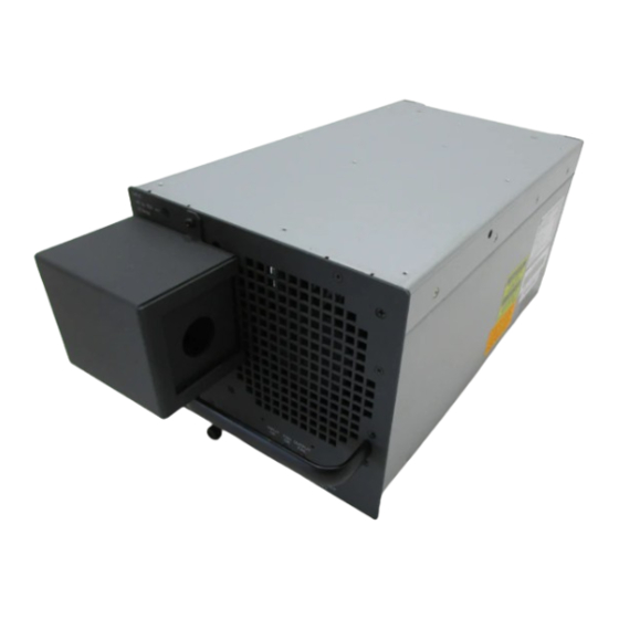
Page 2: Product Overview
The DC-input power supply is a modular power supply for the Cisco 7513 multiprotocol, multimedia router. The DC-input power supply is optional equipment in the Cisco 7513. A second, identical power supply, if installed, provides redundant power. Power supplies reside in power supply bays in the rear of the router chassis, as shown in Figure 1. - Page 3 Product Overview DC-Input Power Supply Specifications Table 1 lists the DC-input power supply specifications. Table 1 Cisco 7513 DC-Input Power Supply Specifications Specification Rating DC-input voltage –40 VDC minimum in North America (–56 VDC in the European Community [E.C.]) –48 VDC nominal, at 33 amps (A) in North America (–60 VDC at 26A in the E.C.) –52 VDC maximum in North America (–72 VDC in the E.C.)
- Page 4 DC-Input Power Supply LED Indications and the Safety Interlock Mechanism On the Cisco 7513 chassis front panel, the power A and power B LEDs go on when the power supply in the corresponding bay is installed and supplying power to the system. Both the power LEDs should be on in systems with redundant power.
-
Page 5: Safety Guidelines
Installation Safety, ESD Precautions, and Tools Required Figure 3 On/off Switch Locking Mechanism Power Locking device switch • A captive installation screw at the bottom of the power supply front panel provides electrical grounding and prevents the power supply from vibrating or sliding out of the bay and dislodging from the power connectors in the backplane. - Page 6 Installation Safety, ESD Precautions, and Tools Required Safety with Electricity You can remove or install a redundant (second) power supply without turning off the other supply. Before removing a redundant power supply, ensure that the first supply is powered on to ensure uninterrupted operation.
-
Page 7: Tools Required
Installation Safety, ESD Precautions, and Tools Required Preventing Electrostatic Discharge Damage Electrostatic discharge (ESD) damage, which can occur when electronic boards or components are handled improperly, can result in complete or intermittent failures. Following are guidelines for preventing ESD damage: •... -
Page 8: Removing And Replacing A Power Supply
Note already connected the system to network interfaces and performed the first-time startup procedures described in the Cisco 7513 Hardware Installation and Maintenance publication. Warning Although it is not necessary to turn OFF both power supplies to remove one of two power supplies, you must turn OFF the power to the power supply you plan to remove. -
Page 9: Removing A Power Supply
Removing and Replacing a Power Supply Removing a Power Supply Follow these steps to remove a power supply. Turn OFF (O) the system power switch on the power supply you are going to remove. Step 1 Before performing any of the following procedures, ensure that power is removed from Warning the DC circuit. - Page 10 Removing and Replacing a Power Supply Use the large slotted screwdriver to loosen the captive screw that secures the power supply Step 4 to the chassis frame. (See Figure 5.) Figure 5 Removing a Power Supply FAN OUTPUT FAN OUTPUT FAIL FAIL POW ER...
-
Page 11: Replacing A Power Supply
To maintain agency compliance requirements and meet EMI emissions standards in Caution Cisco 7513 chassis with a single power supply, the power supply blank must remain in the power supply bay adjacent to the power supply. (See Figure 7.) Do not remove this blank from the chassis unless you do so to install a redundant power supply. - Page 12 Removing and Replacing a Power Supply Attach and tighten the conduit to the conduit bracket. How this conduit is attached depends Step 4 on your site; its attachment is beyond the scope of this documentation. Use the 8-mm nut driver and attach the ground wire to the ground terminal. (See Figure 8.) Step 5 The illustration shows the DC power supply terminal block.
-
Page 13: Checking The Installation
Checking the Installation When you turn ON power to the new power supply, the DC OK LED and the fan OK LED Note will go on and stay on. No other LEDs should go on This completes the power supply replacement procedure. Proceed to the following section “Checking the Installation”... - Page 14 (indicated as either “1200W DC” or “1200W AC”). Record and save this information in a secure place. This completes the power supply installation. Refer to the Cisco 7513 Hardware Installation and Maintenance publication for installation troubleshooting procedures, and to the Router Products Command Reference publication for descriptions and examples of software features and commands.
-
Page 15: Translated Safety Warnings
Translated Safety Warnings Translated Safety Warnings This section repeats in multiple languages the warnings in this guide. Note Ultimate product disposal will be made according to national laws and regulations. Following are translations for the warning statements used in this text. Chassis Lifting Warning Two people are required to lift the chassis. -
Page 16: Lightning Activity Warning
Translated Safety Warnings Il telaio va sollevato da due persone. Afferrare il telaio al di sotto del bordo inferiore Avvertenza e sollevare con entrambe le mani. Per evitare infortuni, mantenere la schiena diritta e sollevare il peso con le gambe, non con la schiena. Per evitare danni al telaio ed ai componenti, non provare mai a sollevare il telaio tramite le maniglie sugli alimentatori o sui processori di interfaccia oppure tramite i pannelli in plastica sulla parte anteriore del telaio. - Page 17 Translated Safety Warnings No operar el sistema ni conectar o desconectar cables durante el transcurso de ¡Advertencia! descargas eléctricas en la atmósfera. Vid åska skall du aldrig utföra arbete på systemet eller ansluta eller koppla loss kablar. Varning! Chassis Warning—Disconnecting Telephone-Network Cables Warning Before opening the chassis, disconnect the telephone-network cables to avoid contact with telephone-network voltages.
-
Page 18: Power Supply Disconnection Warning
Translated Safety Warnings Tämä tuote on riippuvainen rakennukseen asennetusta oikosulkusuojauksesta Varoitus (ylivirtasuojauksesta). Varmista, että vaihevirtajohtimissa (kaikissa virroitetuissa johtimissa) käytetään Yhdysvalloissa alle 120 voltin, 50 ampeerin ja monissa muissa maissa 240 voltin, 30 ampeerin sulaketta tai suojakytkintä. Attention Pour ce qui est de la protection contre les courts-circuits (surtension), ce produit dépend de l'installation électrique du local. -
Page 19: Electric Shock Warning
Translated Safety Warnings Bevor Sie an einem Chassis oder in der Nähe von Netzgeräten arbeiten, ziehen Sie bei Warnung Wechselstromeinheiten das Netzkabel ab bzw. schalten Sie bei Gleichstromeinheiten den Strom am Unterbrecher ab. Prima di lavorare su un telaio o intorno ad alimentatori, scollegare il cavo di Avvertenza alimentazione sulle unità... -
Page 20: Ground Connection Warning
Translated Safety Warnings Ground Connection Warning When installing the unit, the ground connection must always be made first and Warning disconnected last. Waarschuwing Bij de installatie van het toestel moet de aardverbinding altijd het eerste worden gemaakt en het laatste worden losgemaakt. Varoitus Laitetta asennettaessa on maahan yhdistäminen aina tehtävä... - Page 21 Translated Safety Warnings Vor Ausführung der folgenden Vorgänge ist sicherzustellen, daß die Warnung Gleichstromschaltung keinen Strom erhält. Um sicherzustellen, daß sämtlicher Strom abgestellt ist, machen Sie auf der Schalttafel den Unterbrecher für die Gleichstromschaltung ausfindig, stellen Sie den Unterbrecher auf AUS, und kleben Sie den Schaltergriff des Unterbrechers mit Klebeband in der AUS-Stellung fest.
-
Page 22: Dc Power Supply Warning
Translated Safety Warnings La figure illustre le bloc de connexion de l'alimentation en courant continu. Câbler Attention l'alimentation en courant continu en fixant les cosses qui conviennent aux extrémités câblées conformément au schéma. La séquence de câblage à suivre est terre-terre, positif-positif (ligne sur L), et négatif-négatif (neutre sur N). - Page 23 Translated Safety Warnings Jos säikeellinen johdin on tarpeen, käytä hyväksyttyä johdinliitäntää, esimerkiksi Varoitus suljettua silmukkaa tai kourumaista liitäntää, jossa on ylöspäin käännetyt kiinnityskorvat. Tällaisten liitäntöjen tulee olla kooltaan johtimiin sopivia ja niiden tulee puristaa yhteen sekä eristeen että johdinosan. Attention Quand des fils torsadés sont nécessaires, utiliser des douilles terminales homologuées telles que celles à...
- Page 24 Translated Safety Warnings Une fois l'alimentation connectée, retirer le ruban adhésif servant à bloquer la poignée Attention du disjoncteur et rétablir l'alimentation en plaçant cette poignée en position de marche (ON). Nach Verdrahtung des Gleichstrom-Netzgeräts entfernen Sie das Klebeband vom Warnung Schaltergriff des Unterbrechers und schalten den Strom erneut ein, indem Sie den Griff des Unterbrechers auf EIN stellen.
-
Page 25: Cisco Information Online
Bringing the power of internetworking to everyone are service marks, and Cisco, Cisco Systems, the Cisco Systems logo, EtherSwitch, IGRP, Kalpana, LightStream, and UniverCD are registered trademarks of Cisco Systems, Inc. All other trademarks, service marks, registered trademarks, or registered service marks mentioned in this document are the property of their respective owners. - Page 26 Cisco Information Online 26 1200-Watt DC-Input Power Supply Replacement Instructions...