Table of Contents
Advertisement
Quick Links
Doc. No.
78-1900-02
1200-Watt AC-Input Power Supply
Replacement Instructions
Product Number: PWR-7513-AC(=), PWR-7513-ACU(=), PWR-7513-ACA(=),
PWR-7513-ACI(=), and PWR-7513-ACE(=)
This document contains instructions for installing or replacing a 1200-watt (W), alternating current
(AC)–input power supply in the Cisco 7513.
A single power supply is standard equipment for the Cisco 7513. A second, identical power supply,
when installed, provides redundant power.
In systems with redundant power, the power supplies are load-sharing and fully hot-swappable; you
can remove and replace one supply, while the remaining supply immediately ramps up to full power
to maintain uninterrupted system operation.
The sections in this document include the following:
•
•
•
•
•
•
Copyright © 1995
Cisco Systems, Inc.
All rights reserved.
Product Overview, page 2
Environmental Monitoring and Reporting Functions, page 5
Installation Safety, ESD Precautions, and Tools Required, page 10
Removing and Replacing a Power Supply, page 12
Checking the Installation, page 15
Cisco Information Online, page 17
1
Advertisement
Table of Contents

Related Manuals for Cisco PWR-7513-AC


Summary of Contents for Cisco PWR-7513-AC
- Page 1 This document contains instructions for installing or replacing a 1200-watt (W), alternating current (AC)–input power supply in the Cisco 7513. A single power supply is standard equipment for the Cisco 7513. A second, identical power supply, when installed, provides redundant power.
-
Page 2: Product Overview
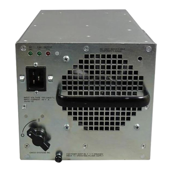
Product Overview Product Overview The AC-input power supply is a modular power supply for the Cisco 7513 multiprotocol, multimedia router. The AC-input power supply is optional equipment in the Cisco 7513. A second, identical power supply, if installed, provides redundant power. Power supplies reside in power supply bays in the rear of the router chassis, as shown in Figure 1. - Page 3 12 American Wire Gauge (AWG), 20-amp 1. VAC = volts direct current. 2. The Cisco 7513 requires a minimum of 20-amp service, with a 20-amp receptacle at the power source. The power cable supplied with the Cisco 7513 uses a 20-amp male plug.
- Page 4 Product Overview On the Cisco 7513 chassis front panel, the power A and power B LEDs go on when the power supply in the corresponding bay is installed and supplying power to the system. Both the power LEDs should be on in systems with redundant power.
-
Page 5: Environmental Monitoring And Reporting Functions
Environmental Monitoring and Reporting Functions Figure 4 On/off Switch Locking Mechanism Power Locking device switch • A captive installation screw at the bottom of the power supply front panel provides electrical grounding and prevents the power supply from vibrating or sliding out of the bay and dislodging from the power connectors in the backplane. -
Page 6: Environmental Monitoring
Environmental Monitoring and Reporting Functions Environmental Monitoring Three sensors on the Route Switch Processor (RSP2) monitor the temperature of the cooling air that flows through the processor slots: inlet, hotpoint, and exhaust. The sensors are located at the bottom, center, and top of the RSP2, when facing the interface processor end of the chassis and viewing the RSP2 as it is installed. - Page 7 Environmental Monitoring and Reporting Functions Table 2 Typical Processor-Monitored Temperature Thresholds Parameter Normal High Warning High Critical Shutdown Inlet 10–40C – Hotpoint 10–40C – Exhaust 10–40C – – – Processors – – – Power supply – – – Restart – –...
- Page 8 Environmental Monitoring and Reporting Functions The show environment command display reports the current environmental status of the system. The report displays parameters that are out of the normal values. No parameters are displayed if the system status is normal. The example that follows shows the display for a system in which all monitored parameters are within Normal range.
- Page 9 (as “Blower #3” indicates in the following example). The system expects to see three blowers or fans in the Cisco 7513: the main system blower, and one fan in each power supply. The system blower is designated #1, the power supply fan in power bay A is #2, and the power supply fan in power bay B is #3.
-
Page 10: Safety Guidelines
• Never try to lift the chassis by yourself; two people are required to lift the Cisco 7513. • Always disconnect all power cords and interface cables before moving the chassis. -
Page 11: Preventing Electrostatic Discharge Damage
Installation Safety, ESD Precautions, and Tools Required Preventing Electrostatic Discharge Damage Electrostatic discharge (ESD) damage, which can occur when electronic boards or components are handled improperly, can result in complete or intermittent failures. Following are guidelines for preventing ESD damage: •... -
Page 12: Removing And Replacing A Power Supply
Note already connected the system to network interfaces and performed the first-time startup procedures described in the Cisco 7513 Hardware Installation and Maintenance publication. Warning Although it is not necessary to turn OFF both power supplies to remove one of two power supplies, you must turn OFF the power to the power supply you plan to remove. -
Page 13: Removing A Power Supply
Removing and Replacing a Power Supply Removing a Power Supply Follow these steps to remove a power supply. Turn OFF (O) the system power switch on the power supply you plan to remove. Step 1 If possible, turn OFF the circuit breaker to which the system is connected and tape the Step 2 breaker switch in the OFF position. -
Page 14: Replacing A Power Supply
To maintain agency compliance requirements and meet EMI emissions standards in a Caution Cisco 7513 chassis with a single power supply, the power supply blank must remain in the power supply bay adjacent to the power supply. (See Figure 7.) Do not remove this blank from the chassis unless you do so to install a redundant power supply. -
Page 15: Checking The Installation
Checking the Installation Checking the Installation To complete the installation, turn the power supply on and observe its LEDs to verify that it is operating properly. Step 1 Review the descriptions of the power supply LEDs on page 4. Step 2 Check the following components to make sure they are secure: •... -
Page 16: Electric Shock Warning
(indicated as either “1200W DC” or “1200W AC”). Record and save this information in a secure place. This completes the power supply installation. Refer to the Cisco 7513 Hardware Installation and Maintenance publication for installation troubleshooting procedures, and to the Router Products Command Reference publication for descriptions and examples of software features and commands. -
Page 17: Cisco Information Online
LAN/X.25, Point and Click Internetworking, SMARTnet, SynchroniCD, Packet, UniverCD, WNIC, Workgroup Director, Workgroup Stack, and XCI are trademarks; Access by Cisco and Bringing the power of internetworking to everyone are service marks; and Cisco, Cisco Systems, the Cisco logo, EtherSwitch, and Kalpana are registered trademarks of Cisco Systems, Inc. All other trademarks, service marks, registered trademarks, or registered service marks mentioned in this document are the property of their respective owners. - Page 18 Cisco Information Online 18 1200-Watt AC-Input Power Supply Replacement Instructions...