ABB Symphony Harmony Series Instructions Manual
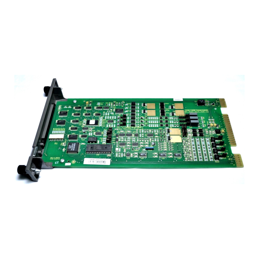
Analog input module
Hide thumbs
Also See for Symphony Harmony Series:
- Instruction (402 pages) ,
- Instructions manual (116 pages) ,
- Instructions manual (66 pages)
Table of Contents
Advertisement
Advertisement
Table of Contents

Related Manuals for ABB Symphony Harmony Series


Summary of Contents for ABB Symphony Harmony Series
- Page 1 Instruction Harmony Series Analog Input Module IMASI23...
- Page 2 Preface The IMASI23 Analog Input Module is a Harmony rack I/O module that is part of the Symphony Enterprise Management and Control System. It has 16 analog input channels that interface isolated thermocouple, millivolt, RTD, and high level analog signals to a controller with an analog-to-digital conver- sion resolution of 24 bits.
- Page 3 List of Effective Pages Total number of pages in this instruction is 82, consisting of the following: Page No. Change Date Preface Original List of Effective Pages Original iii through ix Original 1-1 through 1-10 Original 2-1 through 2-12 Original 3-1 through 3-7 Original 4-1 through 4-11...
- Page 4 Table of Contents Section 1 Introduction ......................1-1 Overview .......................... 1-1 Intended User ........................1-1 Features .......................... 1-1 Instruction Content......................1-3 How to Use this Instruction ....................1-4 Document Conventions ....................1-5 Glossary of Terms and Abbreviations................1-5 Reference Documents....................... 1-5 Related Nomenclature ......................
- Page 5 Table of Contents (continued) Section 2 Description and Operation (continued) Alarm and Exception Reporting................... 2-11 Online Configuration ...................... 2-11 Logic Power ........................2-11 Mounting Hardware......................2-11 Section 3 Installation ......................3-1 Introduction ........................3-1 Special Handling ......................3-1 Unpacking and Inspection ....................3-2 Setup and Installation ......................
-
Page 6: Table Of Contents
Table of Contents (continued) Section 6 Troubleshooting (continued) Error Messages and Corrective Actions................6-3 Input Channel Status ....................6-3 Analog Input Module Errors ..................6-4 Error Example......................6-6 I/O Expander Bus Interface Test ..................6-7 Module Pin Connections....................6-7 Section 7 Maintenance ......................7-1 Introduction........................ - Page 7 List of Figures Title Page 1-1. Harmony Rack I/O Architecture ................ 1-2 2-1. IMASI23 Functional Block Diagram ..............2-2 2-2. Mounting Hardware..................2-12 3-1. Module Layout....................3-3 3-2. S1 Switch ......................3-4 3-3. Six Pin Jumper Block Configurations..............3-5 3-4. Latched and Un-Latched Positions of Captive Latches ........
- Page 8 Safety Summary Electrostatic Sensitive Device Devices labeled with this symbol require special handling precau- tions as described in the installation section. GENERAL Equipment Environment WARNINGS All components, whether in transportation, operation or storage, must be in a noncorrosive environment. Electrical Shock Hazard During Maintenance Disconnect power or take precautions to insure that contact with energized parts is avoided when servicing.
- Page 9 ABB will provide assistance in the operation and repair of its products. Requests for sales or application services should be made to your nearest sales or service office. ABB can also pro- vide installation, repair and maintenance contract services. When ordering parts, use nomenclature or part numbers and part descriptions from equipment manuals.
- Page 10 Trademarks and Registrations Registrations and trademarks used in this document include: ™ Composer Trademark of ABB Automation Inc. ® INFI 90 Registered trademark of ABB Automation Inc. WBPEEUI240774A0...
- Page 11 WBPEEUI240774A0...
- Page 12 Preface The IMASI23 Analog Input Module is a Harmony rack I/O module that is part of the Symphony Enterprise Management and Control System. It has 16 analog input channels that interface isolated thermocouple, millivolt, RTD, and high level analog signals to a controller with an analog-to-digital conver- sion resolution of 24 bits.
- Page 13 List of Effective Pages Total number of pages in this instruction is 82, consisting of the following: Page No. Change Date Preface Original List of Effective Pages Original iii through ix Original 1-1 through 1-10 Original 2-1 through 2-12 Original 3-1 through 3-7 Original 4-1 through 4-11...
- Page 14 Table of Contents Section 1 Introduction ......................1-1 Overview .......................... 1-1 Intended User ........................1-1 Features .......................... 1-1 Instruction Content......................1-3 How to Use this Instruction ....................1-4 Document Conventions ....................1-5 Glossary of Terms and Abbreviations................1-5 Reference Documents....................... 1-5 Related Nomenclature ......................
- Page 15 Table of Contents (continued) Section 2 Description and Operation (continued) Alarm and Exception Reporting................... 2-11 Online Configuration ...................... 2-11 Logic Power ........................2-11 Mounting Hardware......................2-11 Section 3 Installation ......................3-1 Introduction ........................3-1 Special Handling ......................3-1 Unpacking and Inspection ....................3-2 Setup and Installation ......................
- Page 16 Table of Contents (continued) Section 6 Troubleshooting (continued) Error Messages and Corrective Actions................6-3 Input Channel Status ....................6-3 Analog Input Module Errors ..................6-4 Error Example......................6-6 I/O Expander Bus Interface Test ..................6-7 Module Pin Connections....................6-7 Section 7 Maintenance ......................7-1 Introduction........................
- Page 17 List of Figures Title Page 1-1. Harmony Rack I/O Architecture ................ 1-2 2-1. IMASI23 Functional Block Diagram ..............2-2 2-2. Mounting Hardware..................2-12 3-1. Module Layout....................3-3 3-2. S1 Switch ......................3-4 3-3. Six Pin Jumper Block Configurations..............3-5 3-4. Latched and Un-Latched Positions of Captive Latches ........
- Page 18 Safety Summary Electrostatic Sensitive Device Devices labeled with this symbol require special handling precau- tions as described in the installation section. GENERAL Equipment Environment WARNINGS All components, whether in transportation, operation or storage, must be in a noncorrosive environment. Electrical Shock Hazard During Maintenance Disconnect power or take precautions to insure that contact with energized parts is avoided when servicing.
- Page 19 ABB will provide assistance in the operation and repair of its products. Requests for sales or application services should be made to your nearest sales or service office. ABB can also pro- vide installation, repair and maintenance contract services. When ordering parts, use nomenclature or part numbers and part descriptions from equipment manuals.
- Page 20 Trademarks and Registrations Registrations and trademarks used in this document include: ™ Composer Trademark of ABB Automation Inc. ® INFI 90 Registered trademark of ABB Automation Inc. WBPEEUI240774A0...
- Page 21 WBPEEUI240774A0...
- Page 22 Preface The IMASI23 Analog Input Module is a Harmony rack I/O module that is part of the Symphony Enterprise Management and Control System. It has 16 analog input channels that interface isolated thermocouple, millivolt, RTD, and high level analog signals to a controller with an analog-to-digital conver- sion resolution of 24 bits.
- Page 23 List of Effective Pages Total number of pages in this instruction is 82, consisting of the following: Page No. Change Date Preface Original List of Effective Pages Original iii through ix Original 1-1 through 1-10 Original 2-1 through 2-12 Original 3-1 through 3-7 Original 4-1 through 4-11...
- Page 24 Table of Contents Section 1 Introduction ......................1-1 Overview .......................... 1-1 Intended User ........................1-1 Features .......................... 1-1 Instruction Content......................1-3 How to Use this Instruction ....................1-4 Document Conventions ....................1-5 Glossary of Terms and Abbreviations................1-5 Reference Documents....................... 1-5 Related Nomenclature ......................
- Page 25 Table of Contents (continued) Section 2 Description and Operation (continued) Alarm and Exception Reporting................... 2-11 Online Configuration ...................... 2-11 Logic Power ........................2-11 Mounting Hardware......................2-11 Section 3 Installation ......................3-1 Introduction ........................3-1 Special Handling ......................3-1 Unpacking and Inspection ....................3-2 Setup and Installation ......................
- Page 26 Table of Contents (continued) Section 6 Troubleshooting (continued) Error Messages and Corrective Actions................6-3 Input Channel Status ....................6-3 Analog Input Module Errors ..................6-4 Error Example......................6-6 I/O Expander Bus Interface Test ..................6-7 Module Pin Connections....................6-7 Section 7 Maintenance ......................7-1 Introduction........................
- Page 27 List of Figures Title Page 1-1. Harmony Rack I/O Architecture ................ 1-2 2-1. IMASI23 Functional Block Diagram ..............2-2 2-2. Mounting Hardware..................2-12 3-1. Module Layout....................3-3 3-2. S1 Switch ......................3-4 3-3. Six Pin Jumper Block Configurations..............3-5 3-4. Latched and Un-Latched Positions of Captive Latches ........
- Page 28 Safety Summary Electrostatic Sensitive Device Devices labeled with this symbol require special handling precau- tions as described in the installation section. GENERAL Equipment Environment WARNINGS All components, whether in transportation, operation or storage, must be in a noncorrosive environment. Electrical Shock Hazard During Maintenance Disconnect power or take precautions to insure that contact with energized parts is avoided when servicing.
- Page 29 ABB will provide assistance in the operation and repair of its products. Requests for sales or application services should be made to your nearest sales or service office. ABB can also pro- vide installation, repair and maintenance contract services. When ordering parts, use nomenclature or part numbers and part descriptions from equipment manuals.
- Page 30 Trademarks and Registrations Registrations and trademarks used in this document include: ™ Composer Trademark of ABB Automation Inc. ® INFI 90 Registered trademark of ABB Automation Inc. WBPEEUI240774A0...
- Page 31 WBPEEUI240774A0...
- Page 32 Preface The IMASI23 Analog Input Module is a Harmony rack I/O module that is part of the Symphony Enterprise Management and Control System. It has 16 analog input channels that interface isolated thermocouple, millivolt, RTD, and high level analog signals to a controller with an analog-to-digital conver- sion resolution of 24 bits.
- Page 33 List of Effective Pages Total number of pages in this instruction is 82, consisting of the following: Page No. Change Date Preface Original List of Effective Pages Original iii through ix Original 1-1 through 1-10 Original 2-1 through 2-12 Original 3-1 through 3-7 Original 4-1 through 4-11...
- Page 34 Table of Contents Section 1 Introduction ......................1-1 Overview .......................... 1-1 Intended User ........................1-1 Features .......................... 1-1 Instruction Content......................1-3 How to Use this Instruction ....................1-4 Document Conventions ....................1-5 Glossary of Terms and Abbreviations................1-5 Reference Documents....................... 1-5 Related Nomenclature ......................
- Page 35 Table of Contents (continued) Section 2 Description and Operation (continued) Alarm and Exception Reporting................... 2-11 Online Configuration ...................... 2-11 Logic Power ........................2-11 Mounting Hardware......................2-11 Section 3 Installation ......................3-1 Introduction ........................3-1 Special Handling ......................3-1 Unpacking and Inspection ....................3-2 Setup and Installation ......................
- Page 36 Table of Contents (continued) Section 6 Troubleshooting (continued) Error Messages and Corrective Actions................6-3 Input Channel Status ....................6-3 Analog Input Module Errors ..................6-4 Error Example......................6-6 I/O Expander Bus Interface Test ..................6-7 Module Pin Connections....................6-7 Section 7 Maintenance ......................7-1 Introduction........................
- Page 37 List of Figures Title Page 1-1. Harmony Rack I/O Architecture ................ 1-2 2-1. IMASI23 Functional Block Diagram ..............2-2 2-2. Mounting Hardware..................2-12 3-1. Module Layout....................3-3 3-2. S1 Switch ......................3-4 3-3. Six Pin Jumper Block Configurations..............3-5 3-4. Latched and Un-Latched Positions of Captive Latches ........
- Page 38 Safety Summary Electrostatic Sensitive Device Devices labeled with this symbol require special handling precau- tions as described in the installation section. GENERAL Equipment Environment WARNINGS All components, whether in transportation, operation or storage, must be in a noncorrosive environment. Electrical Shock Hazard During Maintenance Disconnect power or take precautions to insure that contact with energized parts is avoided when servicing.
- Page 39 ABB will provide assistance in the operation and repair of its products. Requests for sales or application services should be made to your nearest sales or service office. ABB can also pro- vide installation, repair and maintenance contract services. When ordering parts, use nomenclature or part numbers and part descriptions from equipment manuals.
- Page 40 Trademarks and Registrations Registrations and trademarks used in this document include: ™ Composer Trademark of ABB Automation Inc. ® INFI 90 Registered trademark of ABB Automation Inc. WBPEEUI240774A0...
- Page 41 WBPEEUI240774A0...
- Page 42 Preface The IMASI23 Analog Input Module is a Harmony rack I/O module that is part of the Symphony Enterprise Management and Control System. It has 16 analog input channels that interface isolated thermocouple, millivolt, RTD, and high level analog signals to a controller with an analog-to-digital conver- sion resolution of 24 bits.
- Page 43 List of Effective Pages Total number of pages in this instruction is 82, consisting of the following: Page No. Change Date Preface Original List of Effective Pages Original iii through ix Original 1-1 through 1-10 Original 2-1 through 2-12 Original 3-1 through 3-7 Original 4-1 through 4-11...
- Page 44 Table of Contents Section 1 Introduction ......................1-1 Overview .......................... 1-1 Intended User ........................1-1 Features .......................... 1-1 Instruction Content......................1-3 How to Use this Instruction ....................1-4 Document Conventions ....................1-5 Glossary of Terms and Abbreviations................1-5 Reference Documents....................... 1-5 Related Nomenclature ......................
- Page 45 Table of Contents (continued) Section 2 Description and Operation (continued) Alarm and Exception Reporting................... 2-11 Online Configuration ...................... 2-11 Logic Power ........................2-11 Mounting Hardware......................2-11 Section 3 Installation ......................3-1 Introduction ........................3-1 Special Handling ......................3-1 Unpacking and Inspection ....................3-2 Setup and Installation ......................
- Page 46 Table of Contents (continued) Section 6 Troubleshooting (continued) Error Messages and Corrective Actions................6-3 Input Channel Status ....................6-3 Analog Input Module Errors ..................6-4 Error Example......................6-6 I/O Expander Bus Interface Test ..................6-7 Module Pin Connections....................6-7 Section 7 Maintenance ......................7-1 Introduction........................
- Page 47 List of Figures Title Page 1-1. Harmony Rack I/O Architecture ................ 1-2 2-1. IMASI23 Functional Block Diagram ..............2-2 2-2. Mounting Hardware..................2-12 3-1. Module Layout....................3-3 3-2. S1 Switch ......................3-4 3-3. Six Pin Jumper Block Configurations..............3-5 3-4. Latched and Un-Latched Positions of Captive Latches ........
- Page 48 Safety Summary Electrostatic Sensitive Device Devices labeled with this symbol require special handling precau- tions as described in the installation section. GENERAL Equipment Environment WARNINGS All components, whether in transportation, operation or storage, must be in a noncorrosive environment. Electrical Shock Hazard During Maintenance Disconnect power or take precautions to insure that contact with energized parts is avoided when servicing.
- Page 49 ABB will provide assistance in the operation and repair of its products. Requests for sales or application services should be made to your nearest sales or service office. ABB can also pro- vide installation, repair and maintenance contract services. When ordering parts, use nomenclature or part numbers and part descriptions from equipment manuals.
- Page 50 Trademarks and Registrations Registrations and trademarks used in this document include: ™ Composer Trademark of ABB Automation Inc. ® INFI 90 Registered trademark of ABB Automation Inc. WBPEEUI240774A0...
- Page 51 WBPEEUI240774A0...
- Page 52 Introduction Section 1 Overview The IMASI23 Analog Input Module is a Harmony rack I/O module that is part of the Symphony Enterprise Management and Control System. It has 16 analog input channels that interface isolated thermocouple, millivolt, RTD, and high level analog signals to a controller with an analog-to-digital conver- sion resolution of 24 bits.
-
Page 53: Harmony Rack I/O Architecture
Features C N E T H A R M O N Y A R E A C O N T RO LL E R I/O EX PA N D E R BU S M O D U L E M O D U LE M O D U L E T ER M IN AT IO N C A BL E... - Page 54 Features Three-wire RTD (10, 100 U.S., 100 European, 120 and Chinese 53 ohm). -10 to +10 VDC high level voltage. 4 to 20 milliampere current. Resolution of the analog-to-digital conversion process is 24 • bits. Input type and channel resolution can be selected indepen- •...
- Page 55 Instruction Content Instruction Content This instruction consists of following sections: Introduction Overview of the IMASI23 module including features, descrip- tion, and specifications. Description and Explains the module operation and input circuits. Operation Installation Contains the cautions to observe when handling IMASI23 mod- ules.
-
Page 56: Glossary Of Terms And Abbreviations
(e.g., IMMFP1?). Glossary of Terms and Abbreviations Table contains those terms and abbreviations that are unique to ABB Automation or have a definition that is different from standard industry usage. Table 1-1. Glossary of Terms and Abbreviations Term... -
Page 57: Reference Documents
Reference Documents Reference Documents Table lists ABB Automation instructions for equipment that is referenced in this instruction. Table 1-2. Reference Documents Number Document WBPEEUI200502?0 Module Mounting Unit (IEMMU11, IEMMU12, IEMMU21, IEMMU22) WBPEEUI210504?0 Composer™ Function Code Application Manual WBPEEUI260046?0 Analog Input Termination Unit (NTAI06) -
Page 58: Specifications
Specifications Table 1-4. Specifications (continued) Property Characteristic/Value Analog input channels 16 independently configured channels Thermocouples Type B, E, J, K, L, N (14 AWG), N (28 AWG), R, S, T, U Chinese type E and Chinese type S 3-wire RTD platinum: U.S. - Page 59 Specifications Table 1-4. Specifications (continued) Property Characteristic/Value Cold junction reference ± 0.5° C accuracy Software temperature ± 0.1° C linearization accuracy Common mode isolation 250 VDC/V at 60 Hz Normal (IEC 61010-1, IEC 60255-5, Test Common Mode Mode IEC 60060) Insulation resistance 100 M 9 Channel to channel and chan-...
- Page 60 Specifications Table 1-4. Specifications (continued) Property Characteristic/Value Magnetic and electromagnetic fields Power frequency magnetic Continuous: 30 A field (IEC 61000-4-8, EN Short duration: 300 A 61000-4-8) Pulse magnetic field (IEC Peak value: 300 A/m 61000-4-9, EN 61000-4-9) Damped oscillatory magnetic Peak value: 30 A/m field, 0.1 MHz and 1 MHz (IEC 61000-4-10, EN 61000-4-10)
- Page 61 Specifications Table 1-4. Specifications (continued) Property Characteristic/Value CE mark declaration This product, when installed in a Symphony cabinet, complies with the following Directives/Standards for CE marking. EMC96 Directive 89/336/EEC EN50082-2 Generic Immunity Standard - Part 2: Industrial Environment EN50081-2 Generic Emission Standard - Part 2: Industrial Environment Low Voltage Directive 73/23/ EN61010-1 Safety Requirements for Electrical Equipment for...
-
Page 62: Introduction
Description and Operation Section 2 Introduction This section explains the inputs, control logic, communication, and connections for the IMASI23 module. The ASI module interfaces 16 analog inputs to a Harmony controller. The Har- mony controller communicates with its I/O modules over the I/O expander bus (Fig. -
Page 63: Imasi23 Functional Block Diagram
Functional Operation Each channel provides underrange, overrange, and open input detection. Onboard circuitry detects either open field wires or a disconnected termination unit cable. Open input detection is provided for millivolt, thermocouple, RTD, 1 to 5 VDC, and 4 to 20 milliampere input types and can detect any combination of open input wires. - Page 64 Functional Operation connections made by terminating the field wires (thermocouple wires) onto the terminal blocks of the termination unit. The block address of the cold junction reference used by ther- mocouple inputs on the ASI module is contained in FC 215, specification S3.
- Page 65 I/O Expander Bus LED Indicators The ASI module has two LED indicators, one red and one green, which show the operating status. The LEDs will: Flash red on power-up. • Remain off (both LEDs) after passing onboard diagnostics • until the ASI module is configured by the controller. Show solid green after the controlling controller downloads •...
- Page 66 I/O Expander Bus I/O Expander Bus Interface The ASI module communicates with the controller through a shared memory interface connected to the I/O expander bus. The ASI module constantly updates the shared memory device (dual port RAM) with the current values of the inputs. The con- troller can read these values at any time, even if the ASI mod- ule is simultaneously writing to the dual port RAM.
- Page 67 Automatic Adjustments and Corrections module. The system power supply is protected from short cir- cuits by fuses on the NTAI06 termination unit. Function Codes NOTE: Refer to Appendix C for function code specification changes required when replacing an IMASI03 module with an IMASI23 module. FCs 215 and 216 in the controller configure the ASI module and identify the active analog inputs.
- Page 68 Automatic Adjustments and Corrections Point Value Calculation The ASI module maintains a set of adjustment values for each input channel. These values correct for offset and gain errors in the input channel. The raw analog-to-digital converter count value is converted to an actual input signal value using the cal- ibration data.
- Page 69 Automatic Adjustments and Corrections User Gain and Offset Adjustment A user-specified linear adjustment can be applied to the input signal before it is converted to engineering units. This gain and offset is applied to the value obtained after all compensation and correction operations are performed.
- Page 70 Diagnostic, Security, and Integrity Checks through a square root, polynomial, or other function block fol- lowed by a scaling function to provide the value in engineering units. Automatic Calibration Compensation for drift of input channel circuitry is done by periodic automatic calibration of each A/D converter using an internal precision low-drift reference.
- Page 71 Diagnostic, Security, and Integrity Checks DPRAM test. • NVRAM test. • SRAM test. • System reference checks. • Configured channel reference checks. • Unconfigured channel reference checks. • Diagnostics During Normal Operation During startup, the ASI module verifies the checksum of the PROM and nonvolatile RAM.
- Page 72 (P1) at the back of the ASI module. Mounting Hardware Harmony rack I/O modules and termination units mount in standard ABB Automation enclosures (CAB-01, CAB-04, CAB-12). The number of modules that can be mounted in a single cabinet varies.
-
Page 73: Mounting Hardware
Mounting Hardware M O D U LE M O U N TIN G U N IT M O D U L E C A BIN E T SID E R A IL S FIE L D TE R M IN AT IO N PA N E L T ER M IN AT IO N U N IT... -
Page 74: Introduction
IMASI23 module. Special Handling NOTE: Always use the ABB Automation field static kit (part number 1948385A1), consisting of two wrist straps, ground cord assembly, alligator clip, and static dissipating work surface when working with static sensitive devices. - Page 75 Unpacking and Inspection 1. Examine the hardware immediately to verify it has not been damaged in transit. 2. Notify the nearest ABB Automation sales office of any such damage. 3. File a claim for any damage with the transportation com- pany that handled the shipment.
-
Page 76: Module Layout
Setup and Installation 6. Verify there is sufficient logic and field power for the mod- ules in the module mounting unit. Address Selection Switch (S1) The ASI module must have an address to communicate with the controller. The ASI module can have any one of 64 addresses (address 0 to 63) on the I/O expander bus. -
Page 77: S1 Switch
Setup and Installation O PE N M SB L S B M U S T R EM AIN AD D R ESS C LO SE D N OT E: O P E N PO S ITIO N = L O G IC 1 T 01 80 0 A Figure 3-2. -
Page 78: Six Pin Jumper Block Configurations
Setup and Installation Refer to figure for the jumper block configurations. m V /T C V /m A R TD T 04 35 5 A Figure 3-3. Six Pin Jumper Block Configurations Termination Unit Configuration An NTAI06 termination unit connects the field device wiring to the Symphony system. -
Page 79: Latched And Un-Latched Positions Of Captive Latches
Wiring Connections and Cabling 4. Align the module with the guide rails in the module mount- ing unit. Carefully slide the module in until the front panel is flush with the top and bottom of the MMU frame. 5. Push and turn the two captive latches on the module face- plate one half turn to the latched position. -
Page 80: Cable Connections
Wiring Connections and Cabling Cable Connections The IMASI23 module uses one NTAI06 termination unit for ter- mination. The NTAI06 requires an NKAS01 or NKAS11 cable to connect to the IMASI23 module. The cables have a Y configura- tion with two connectors on one end. Note the labeling of J2 and J3 to insure proper connection of the input signals. - Page 81 WBPEEUI240774A0...
-
Page 82: Introduction
Configuration and Calibration Section 4 Introduction This section explains the configuration and optional field cali- bration for the field inputs of the IMASI23 module (ASI). Function codes in the controller configure the IMASI23 module and identify the active analog inputs. These function codes specify the I/O expander bus address of the ASI module and the number of active channels on the input module. - Page 83 Configuring Function Codes IMASI23 module as well as the channel number on the analog input module connected to an analog input signal. The type of the input, as well as the zero and span in engineering units, must also be specified to insure proper scaling and corrections for field calibration or cold junction compensation.
- Page 84 Calibrating Inputs Calibrating Inputs Calibration is done at the factory and the calibration data is stored on the IMASI23 module in nonvolatile memory. No field calibration is necessary. If, however, field calibration is Field Calibration desired, use the procedure described in this section.
- Page 85 Field Calibration function block. It reflects the status of the most recently issued calibration command. The status of a channel field calibration is also reported as an output (N+1) of this function block. This output shows the sta- tus for the channel referenced in the most recent field calibra- tion command.
- Page 86 Field Calibration S4 sets the input type (zero equals millivolt). • S5 sets the amount of gain. Set S5 to the gain value. • S6 sets the offset value. Set S6 to the offset value. • Check block N+2 or block N+3 to see if the set user gain and offset command is processed correctly, and is incorporated into ASI module input reading of that channel and type.
- Page 87 Field Calibration Before performing a point field calibration, ultra stable, known, precise values are connected to the input channel. During point calibration, the ASI module reads the input and stores its digitized value. Two point calibrations within an input range must be performed.
- Page 88 RTD input. The high level, low level, and three-wire RTD inputs can be field calibrated with this procedure. ABB Automation recommends checking the accuracy of the channel within each of the specified ranges after calibrating each channel.
- Page 89 Field Calibration Individual Channel Calibration This section provides field calibration procedures for low level, high level, and resistance. To calibrate each channel in the module: 1. Configure the point in the system. 2. Disable the channel. 3. Calibrate the channel with two calibration points. 4.
- Page 90 Field Calibration and use these steps to configure high level, or resistance inputs. Also S4 of FC 216 must be consistent with the type of calibration being performed. 1. Locate the block address in the controller of FC 217. 2. Verify that the I/O expander bus dipshunts are in place to allow ASI module bus communications.
- Page 91 Field Calibration 10. Tune FC 217, specification S5 to the input voltage or resis- tance value. For this example, tune these specifications: a. Perform point calibration (S1 = 2). b. ASI module referenced by FC 215 at block address 100 (S2 = 100).
- Page 92 Field Calibration A successful enable operation can be verified by checking FC 217, outputs N+1 and N+4 for a zero value. If the enable was unsuccessful, an error code will appear in the FC 217, outputs N+1 and N+4 which can aid in troubleshooting. WBPEEUI240774A0 4 - 11...
- Page 93 WBPEEUI240774A0...
- Page 94 Operating Procedures Section 5 Introduction This section explains the startup and operation of the IMASI23 module (ASI). Startup Communication between the ASI module and controller starts when the two modules are configured correctly (refer to Section 4). The ASI module address in FCs 215 and 216 must be the same as the address set on the address dipswitch.
- Page 95 Status LEDs Status LEDs The IMASI23 module has two LEDs, one red and one green, that show its operating status. Red flashes on power up. • Both remain off after passing onboard diagnostics until the • ASI module is configured by the controller. Green is solid after the controller downloads configuration •...
- Page 96 Troubleshooting Section 6 Introduction This section explains the error signs and corrective actions for the IMASI23 module (ASI). Status LEDs The IMASI23 module has two LEDs, one red and one green, that show its operating status. Refer to Status LEDs Status LEDs Status LEDs Status LEDs...
-
Page 97: Imasi23 Error Types
Problem Reports If the detailed module status read from the ASI module by • the controller indicates any error conditions. If the channel status for any configured channel indicates • an error. Table contains the error types generated for each error. Table 6-1. - Page 98 Error Messages and Corrective Actions Table 6-1. IMASI23 Error Types (continued) Module Problem Report Type 12 Error Analog Input Module Error Description Corrective Actions Type Error Calibration (02H) problem Unconfigured Cold junction reference is not zero report (from FC 215) reference error and has bad quality.
-
Page 99: Module Status (Byte 3) Error Codes
FC 215 Spec S1. Reinsert IMASI23 and verify Indicated FC 215 block detected proper seating. If error recurs, call an IMASI23 error. (IMASI23 mod- ABB Automation field service. ule firmware has reported an error.) 6 - 4 WBPEEUI240774A0... - Page 100 Error Messages and Corrective Actions Table 6-2. Module Status (Byte 3) Error Codes (continued) Error Error Description Corrective Actions Code Message Configuration Indicated FC 215 or FC 216 Verify FC 215 spec values and all Error - detected a function code channel linked FC 216s are correct.
- Page 101 Error Messages and Corrective Actions error block. For example, if byte four contains a 10 and byte five contains a 42, then block 1042 contains the error. For more information on module status, refer to the appropri- ate controller instruction. Error Example FC 215 for the ASI module and 216 for the active channel need the same address.
- Page 102 I/O Expander Bus Interface Test I/O Expander Bus Interface Test The I/O expander bus test checks for proper operation of the following interface components. I/O expander bus interface. • Dual port static RAM (ASI module read/writes and control- • ler read/writes). Controller and ASI module handshaking.
-
Page 103: P1 Power Connections
Module Pin Connections Table 6-3. P1 Power Connections Signal Signal +5 VDC Not used +5 VDC Not used Not used Power fail interrupt Not used Not used Common Not Used Common Not Used Table 6-4. P2 Expander Bus Connections Signal Signal Data 1 Data 7... -
Page 104: P3 Input Signal Connections
Module Pin Connections Table 6-5. P3 Input Signal Connections Signal Signal RTD- RTD+ IN1+ IN1- COM1 COM2 IN2- IN2+ IN3+ IN3- COM3 COM4 IN4- IN4+ IN5+ IN5- COM5 COM6 IN6- IN6+ IN7+ IN7- COM7 COM8 IN8- IN8+ IN9+ IN9- COM9 COM10 IN10- IN10+... - Page 105 WBPEEUI240774A0...
-
Page 106: Preventive Maintenance Schedule
Section 7 Introduction The reliability of any stand-alone product or control system is affected by the maintenance of the equipment. ABB Automa- tion recommends that all equipment users practice a preven- tive maintenance program that will keep the equipment operating at an optimum level. - Page 107 Equipment and Tools Required Table 7-1. Preventive Maintenance Schedule Task Frequency Check cabinet air filters. Clean or replace them as necessary. Check the air filter 3 months more frequently in excessively dirty environments. Check cabinet and module for dust. Clean as necessary using an antistatic vacuum. Check all module signal, power and ground connections within the cabinet.
- Page 108 Preventive Maintenance Procedures This section covers tasks from Table that require specific instructions or further explanation. Cleaning printed circuit boards and edge connectors. • Checking signal, power and ground connections. • Printed Circuit Board Cleaning There are several circuit board cleaning procedures in this sec- tion.
- Page 109 Preventive Maintenance Procedures 5. Dry the edge connector contact area by wiping with a clean lint free cloth. To clean tarnished or deeply stained edge connector contacts: 1. Use a nonabrasive eraser or equivalent to remove tarnish or stains. Fiberglass or nylon burnishing brushes may also be used.
- Page 110 Repair and Replacement Section 8 Introduction This section explains the replacement steps for a IMASI23 module (ASI). There are no special tools required to replace an ASI module. NOTE: Refer to Appendix C for information about replacing an IMASI03 or Appendix B on an IMASI13 module with an IMASI23 module.
- Page 111 WBPEEUI240774A0...
- Page 112 NTAI06 Termination Unit Appendix A Introduction The IMASI23 module (ASI) uses one NTAI06 termination unit for termination. Jumpers on the termination unit configure each of the 16 analog inputs for either system powered 4 to 20 milliamperes, external powered 4 to 20 milliamperes, three-wire RTD, differential voltage, or single ended voltage.
-
Page 113: Ntai06 Layout (Rev A Hardware
Configuring Inputs J3 3 TB 2 T B 1 J5 7 J1 7 J1 0 J3 4 – – J2 6 J5 8 – F 10 – J1 1 J5 9 J1 9 F 11 J3 6 J2 0 J5 2 –... -
Page 114: Ntai06 Layout (Rev B Hardware
Configuring Inputs J 41 J 33 T B2 TB 1 J 25 J 57 J 17 J 49 J 10 J 42 J 34 – – J 26 J 58 J 18 J 50 – – F 10 J 43 J 11 J 35 J 27... -
Page 115: Ntai06 Jumper Configurations
Configuring Inputs Table A-1. NTAI06 Input Types (continued) Input Type Signal Type Current 4 to 20 mA, external or system powered 3-wire RTD Resistance range: 0 to 500 9 RTDs: 10, 100, 120 9 Chinese 53 9 (3-wire) Table A-2. NTAI06 Jumper Configurations Jumper Number Input Type J1 - J32... -
Page 116: Ntai06 Input Type Descriptions
Configuring Inputs Table A-3. NTAI06 Input Type Descriptions (continued) Input Type Input Description External powered This jumper configuration connects the plus (+) input terminal to one end of a 4-20 mA precision resistor and the minus (-) input to the other end of the same preci- sion resistor located on the NTAI06. -
Page 117: Ntai06 Input Circuit
Configuring Inputs A B B R E P L A CE M E NT F U S E PA RT N U M B E R FO R F 1 -F 16: 1 94 58 20A 10 310 F IE L D IN P U T J3 3-J48 J1 -J16 F 1 -F 16... -
Page 118: Ntai06 Field Input Termination Examples
Configuring Inputs T B 2 T B 1 C H A N N E L 5 (D IF F E R EN T IAL – – V O LTAG E ) – – LTO TA L C H A N N E L 6 TR A N S M IT T E R 4-2 0 m A (S Y S T E M -PO W E R E D... -
Page 119: Imasi23 Input Examples
Configuring Inputs N TAI06 TE R M IN AT IO N U N IT IM A SI23 +24 V TR A N S M IT TE R FU S E N K AS 01/11 C A B LE – 0.4-2 V I/O C O M 250 9 S Y ST EM -P O W E R E D... -
Page 120: Ntai06 Cable Connection
Configuring Inputs T E R M IN AT IO N U N IT C A B L E C H A N N E L S 1 1 -1 6 FIE L D IM A SI23 N TAI06 W IR IN G N K A S0 1 /1 1 (N OT E 1 ) C H A N N E L S 1 -10... - Page 121 WBPEEUI240774A0...
-
Page 122: Appendix B Replacing An Imasi13 Module
Replacing an IMASI13 Module Appendix B Introduction The IMASI13 module and the IMASI23 module are similar. The minimal differences are discussed in this section. User Differences The only user differences between the IMASI23 and the IMASI13 is the input configuration jumper blocks J1-J16. The IMASI13 has 4 pin jumper blocks, where the IMASI23 has 6 pin jumper blocks. -
Page 123: Power Consumption Comparison
Power Consumption Comparison nation Unit do not have to be removed if using the input for a thermocouple, millivolt or milliamp inputs. RTD Input If there are jumpers added between the minus (-) and the C ter- minals on the NTAI06 Termination Unit, they must be removed if the inputs are to be configured for RTD input. -
Page 124: Appendix C Replacing An Imasi03 Module
Replacing an IMASI03 Module Appendix C Introduction There are two differences between the IMASI03 modules and the IMASI23 module, resolution/scan time and power con- sumption. Once these two factors are taken into consideration, the IMASI23 module can be used as a direct replacement for the IMASI03 module. -
Page 125: Function Code 216 Modifications
Function Code 216 Modifications IN P U T IN P U T C H A N N E L 1 C H A N N E L 1 6 S TATU S LE D E D G E C O N N E C TO R S 1 2 3 4 5 6 7 8 S W 1 O P EN... - Page 126 Power Consumption Comparison Power Consumption Comparison IMASI03 module: 300 mA at +5 VDC • 130 mA at +15 VDC • 35 mA at -15 VDC • IMASI23 module: 500 mA at +5 VDC • In most instances, this small difference in power consumption will not require any changes to the power supplies.
- Page 127 WBPEEUI240774A0...
- Page 128 Index Configuring inputs ........3-4, 4-1 Connectors P1, P2, P3 ........3-6 Address switch (S1)........3-3 Continue - Do Not Display Error .....6-6 Alarm and exception reporting....2-11, 6-1 Controller errors ..........6-2 Analog inputs ..........1-2 Conventions, document ........1-5 Automatic adjustments and corrections Corrective actions for error messages ....6-2 Automatic calibration ........
- Page 129 Index (continued) Functional operation Glossary of terms and abbreviations ... 1-5 I/O expander bus..........2-4 How to use ..........1-4 I/O expander bus interface......2-5 Intended user ..........1-1 Input multiplexer (MUX) .......2-3 LED indicators..........2-4 Microcontroller and memory......2-3 Jumper Switch settings ..........2-3 Channel ............
- Page 130 Index (continued) Open input detection........2-10 Select address ..........3-3 Offset and gain adjustment......2-8 Setup and installation Onboard indicators ......2-4, 5-1, 6-1 Address switch (S1) ........3-3 Online configuration........2-11 Binary address ..........3-3 Open input detection ......1-3, 2-10 Configuring inputs ........3-4 Operating modes ..........6-6 Jumper configuration ........3-4 Operating procedures ......5-1, 6-1 Jumper location..........3-4...
- Page 131 WBPEEUI240774A0...
- Page 132 Telefax 65-756-7309 Telephone 49-6196-800-0 Telefax 39-010-6584-941 Telefax 49-6196-800-1119 Form WBPEEUI240774A0 Litho in U.S.A. Sept2000 Copyright © 2000 by ABB Automation Inc., as an Unpublished Work, All Rights Reserved ® Registered Trademark of ABB Automation Inc. ™ Trademark of ABB Automation Inc.