Table of Contents

Related Manuals for Nagra PL-P


Summary of Contents for Nagra PL-P
- Page 1 Nagra PL-P Preamplifier Owner’s Instruction Manual NAGRAVISION SA KUDELSKI GROUP Route de Genève 22 CH-1033 Cheseaux Switzerland Phone +41 (0) 21 732-0101 Fax +41 (0) 21 732-0100 E-mail info@nagra.com All rights reserved – © May 2003 (P/N: 2055001151)
-
Page 2: Table Of Contents
T T a a b b l l e e o o f f C C o o n n t t e e n n t t s s Table of Contents Congratulations Warranty About your PL-P Basic Operations Battery Operation of the PL-P Battery Installation Connecting the PLP-CCC3 AC Power Supply Vacuum Tube Identification and Location Tube, Jumpers and Timer Positions Burn-in Period... -
Page 3: Congratulations
Lampes - Phono) is designed to provide the highest quality of audio performance in an ultra-high resolution audio system, especially one with a competent vinyl LP playback source. The Nagra PL-P was created by an engineering team with over 45 years of experience designing world-class... -
Page 4: Warranty
W W a a r r r r a a n n t t y y Warranty NAGRA/KUDELSKI certifies that this instrument was thoroughly inspected and tested prior to leaving our factory and is in accordance with the data given in the accompanying test sheet. -
Page 5: About Your Pl-P
• The PL-P case CNC- machined in hardened, anodized • The power supply of the PL-P is aluminium. It is designed to designed to deliver quiet and provide many years of service stable performance suitable for and to comply with all existing... -
Page 6: Basic Operations
B B a a s s i i c c O O p p e e r r a a t t i i o o n n s s Basic Operations Photograph showing the Nagra PL-P, the PLP-CCC3 charger and two battery “batons” Battery Operation of the PL-P... -
Page 7: Battery Installation
Battery Installation A battery compartment at the rear PLP-CCC3 AC power supply of the PL-P is designed to hold 8 unit. “D”-size power cells. The PL-P is delivered from the factory with 2... -
Page 8: Connecting The Plp-Ccc3 Ac Power Supply
See next section for have the posit-ive end of all cells full instructions. facing the right side of the PL-P, Connecting the PLP-CCC3 AC Power Supply Once the batteries are properly installed in the PL-P, the male... - Page 9 PL-P are being properly managed, the • The rechargeable power cells in I- LED will light. The intensity of the PL-P are faulty and will not this LED indicates the rate of accept a charge. charging supplied to the PL-P.
-
Page 10: Vacuum Tube Identification And Location
To reconnecting the power supply. Do ensure complete battery not use the PL-P for a about 90 discharge, operate PL-P minutes while the recharging cycle without the PLP-CCC3 connected is initiated. Normal operation can until the recharge-able power cells then resume. - Page 11 To seat each vacuum tube properly, ensure that the PL-P is powered off, disconnect the PLP-CCC3 AC power supply unit and remove the top plate. If the unit has just been powered off, please wait 5 minutes for the vacuum tubes to cool down before handling them.
-
Page 12: Tube, Jumpers And Timer Positions
Tube, Jumpers and Timer Positions Line stage tube timer Phono stage tube timer 12AX7(ECC83) Phono input stage Jumpers 12AX7 (ECC83) Line output stage 12AT7 (ECC81) Line output stage Phono transformers 12AX7 (ECC83) Line input stage Headphone transformers 12AT7 (ECC81) Phono output stage 12AT7 (ECC81) Line input stage... -
Page 13: Burn-In Period
Burn-in Period With the Nagra PL-P a period of had an opportunity to reach its full about 250-300 hours of use will performance potential. Serious allow all components within the audition and permanent installation circuits to reach a level of operating options should only be evaluated equilibrium. -
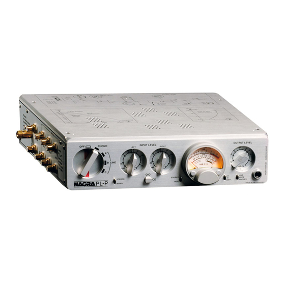
Page 14: Front Panel/Control Layout
The Main Rotary Switch • “PHONO” - Power is supplied to all active electronic stages. A 15- Powering the PL-P and input second mute function engages selection is provided through the when the main rotary switchis... - Page 15 Modulometer Left Right Input highly precise, Nagra-made Potentiometers modulometer provides a multitude of indications through 2 coaxial, Input level gain for each channel internal pointers representing the can be controlled via the left and left and right channels.
-
Page 16: Right Panel/Output Layout
This is a ” stereo jack connector. panel. The level is controlled using the output potentiometer. The normal • In the middle position, output is audio outputs of the PL-P are muted for both “LINE” and muted when headphones “PHONES” connectors. -
Page 17: Advanced Operations
A A d d v v a a n n c c e e d d O O p p e e r r a a t t i i o o n n s s Advanced Operations Input Customization The inputs of the PL-P can be customized suit... - Page 18 4. RIAA Equalization options options The PL-P can be selected to work PL-P offers following with one of two RIAA equalization resistive and capacitive loading curves by installing jumpers ST1...
-
Page 19: Using The Modulometer
On the inside left of the PL-P case optimum operating range for each is a printed circuit board which is input source and the PL-P. connected to the input connectors of Line A, Line B and Line C. -
Page 20: Modulometer Calibration And Its Use
pointer advances and stays for a a reading to be taken. sufficient time order modulometer measures signals that can affect systems • VU Meter prone to overloading such as On the contrary versus the amplifiers and radio transmitters. modulometer, the VU meter has It shows signal peaks that would the same rise and fall time. -
Page 21: Block Diagram
Block Diagram Output Customization, Tape Loop Input Adjustment The PL-P is equipped with a tape loop for connection to the inputs and outputs of tape recorders or other external signal processing equipment. To select operations using the tape loop, select the “TAPE” position on the Source/Tape switch on the front panel. -
Page 22: Hum
AC ground loops. To the isolation of the phase. deal with this, the PL-P is designed to cover a number of technical In principle, this wire carries no points,... - Page 23 Neutral + earth POWER AMP PL-P Once the theory above is understood, the recommendations which are to follow may seem somewhat evident. For those who have not followed to this point, simply pay careful attention to the following elementary rules.
- Page 24 Power Spot PL-P Amplifier 2. From your single power socket, try as much as possible to use “single point” connection rather than multi point (see below). Incorrect multipoint...
- Page 25 Amplifier CD Player Power PL-P 3. A third solution, which is equally viable, is to connect the individual units to the wall connector starting with the highest power consumers and finishing with the lowest power consumer and equally the units using high-level audio signals together and those with lower levels together, as indicated in the diagram below.
-
Page 26: Connection Of Your Plp
Connection of your PLP Once if the points mentioned above are respected, the connections between the PL-P and the amplifier as well as those connected to the line inputs of the PL-P should cause no problems. Only the connection to the turntable must be done with great care. The feeble signal levels coming from the cartridge of the tone-arm can easily be disturbed if the installation is not correct. - Page 27 (A1, B1 and C1). A1. Single-block turntable If hum still exists, then verify that the two main power cords (of the PL-P and the turntable) are connected to the mains supply, as close as possible to each other as suggested above in the connection explanation.
- Page 28 “X” is obligatory. For those who have a high-output MM cartridge fitted to the tone-arm, you can bypass the input transformers if desired (see jumpers section). If this is the case you lose the facilities of Tone-arm PL-P floating solutions mentioned above.
-
Page 29: Specifications
S S p p e e c c i i f f i i c c a a t t i i o o n n s s Specifications Electrical Phono stage Moving coil Sensitivity Loading 0.1 ~ 47kΩ S/N ratio 0.5 mV, A-weighted Moving magnet Sensitivity... -
Page 30: Safety/Compliance
Safety compliance DÉCLARATION DE CONFORMITÉ DECLARATION OF CONFORMITY FABRICANT: NAGRA - KUDELSKI, 1033 Cheseaux SUISSE MANUFACTURER: NAGRA-KUDELSKI, 1033 CHESEAUX, SWITZERLAND APPAREIL : PL-P et PLP-CCC3 MODEL: PL-P and PLP-CCC3 NORMES GÉNÉRIQUES APPLICABLES : APPLICABLE GENERIC NORMS: EN 50081-1 (92) pour les émissions For Emissions EN 50082-1 (92) pour l'immunité... - Page 31 NAGRA, KUDELSKI are trademarks, property of KUDELSKI S.A., CHESEAUX SWITZERLAND. All specifications contained in this publication are subject to change at any time without prior notice following improvvements and or modifications of the equipment. COPYRIGHT RESERVED FOR ALL COUNTRIES. PRINTED IN SWITZERLAND...