Table of Contents
Advertisement
Quick Links
PEN00537-05
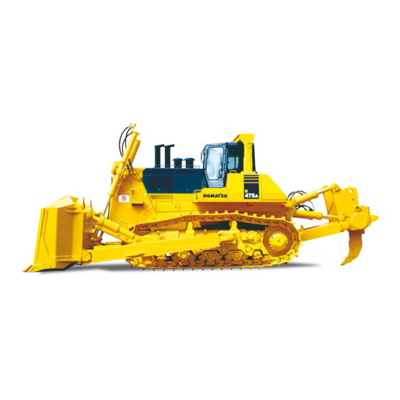
BULLDOZER
D475A
-5E0
30134
SERIAL NUMBERS
and up
WARNING
Unsafe use of this machine may cause serious injury or
death. Operators and maintenance personnel must read
this manual before operating or maintaining this machine.
This manual should be kept near the machine for
reference and periodically reviewed by all personnel who
will come into contact with it.
NOTICE
Komatsu has Operation & Maintenance Manuals
written in some other languages. If a foreign language
manual is necessary, contact your local distributor for
availability.
Advertisement
Chapters
Table of Contents

Related Manuals for Komatsu D475A-5E0


Summary of Contents for Komatsu D475A-5E0
- Page 1 This manual should be kept near the machine for reference and periodically reviewed by all personnel who will come into contact with it. NOTICE Komatsu has Operation & Maintenance Manuals written in some other languages. If a foreign language manual is necessary, contact your local distributor for availability.
- Page 2 1 - 1...
-
Page 3: Read This Manual
If this manual is lost or damaged, contact your distributor immediately to arrange for its replacement. For details regarding the machine serial No. you will need to provide your Komatsu distributor, see "TABLE TO ENTER SERIAL NO. AND DISTRIBUTOR (PAGE 1-8)". -
Page 4: Safety Information
FOREWORD SAFETY INFORMATION SAFETY INFORMATION To enable you to use the machine safely, and to prevent injury or death to operators, service personnel or bystanders, the precautions and warnings included in this manual and the safety signs attached to the machine must always be followed. -
Page 5: Introduction
FOREWORD INTRODUCTION INTRODUCTION USE OF MACHINE This Komatsu machine is designed to be used mainly for the following work: Dozing Cutting into hard or frozen ground or ditching Felling trees, removing stumps Pushing Ripping For further details, see "WORK POSSIBLE USING BULLDOZER (PAGE 3-144)" and "RIPPER OPERATION (PAGE 3-151)". -
Page 6: Visibility From Operator's Seat
FOREWORD INTRODUCTION VISIBILITY FROM OPERATOR'S SEAT The visibility standards (ISO 5006) for this machine require a view shown in the following figure. PROXIMITY VISIBILITY The visibility of this machine in the area 1 m (3 ft 3 in) from the outside surface of the machine at a height of 1.5 m (4 ft 11 in) is shown in the following figure. -
Page 7: Necessary Information
NECESSARY INFORMATION NECESSARY INFORMATION When requesting service or ordering replacement parts, contact your Komatsu distributor of the following items. PRODUCT IDENTIFICATION NUMBER (PIN), MACHINE SERIAL NO. PLATE This is inside the console box on the left side of the operator's seat. -
Page 8: Blade Serial No. Plate Position
FOREWORD NECESSARY INFORMATION BLADE SERIAL NO. PLATE POSITION This is located on the upper right of blade back surface. RIPPER SERIAL NO. PLATE POSITION This is located on the left side surface of ripper beam. POSITION OF SERVICE METER On top of the machine monitor 1 - 7... - Page 9 FOREWORD NECESSARY INFORMATION TABLE TO ENTER SERIAL NO. AND DISTRIBUTOR Machine serial No. Engine serial No. Product identification number (PIN) Distributor name Address Service Personnel Phone/Fax 1 - 8...
-
Page 10: Table Of Contents
FOREWORD CONTENTS CONTENTS FOREWORD READ THIS MANUAL SAFETY INFORMATION INTRODUCTION USE OF MACHINE FRONT/REAR, LEFT/RIGHT DIRECTIONS OF MACHINE VISIBILITY FROM OPERATOR'S SEAT NECESSARY INFORMATION PRODUCT IDENTIFICATION NUMBER (PIN), MACHINE SERIAL NO. PLATE ENGINE SERIAL NUMBER PLATE BLADE SERIAL NO. PLATE POSITION RIPPER SERIAL NO. - Page 11 FOREWORD CONTENTS DOOR OPEN LOCK 3- 54 SASH GLASS INTERMEDIATE LOCK 3- 54 CAP WITH LOCK 3- 55 DOOR POCKET 3- 56 ASHTRAY 3- 57 TOOL BOX 3- 57 CLEAN INTERIOR OF CAB 3- 57 CAR STEREO, HANDLING 3- 58 AIR CONDITIONER, HANDLING 3- 67 BATTERY DISCONNECT SWITCH...
- Page 12 4- 10 WEAR PARTS LIST 4- 10 RECOMMENDED FUEL, COOLANT, AND LUBRICANT 4- 12 RECOMMENDED BRANDS, RECOMMENDED QUALITY FOR PRODUCTS OTHER THAN KOMATSU GENUINE OIL 4- 14 STANDARD TIGHTENING TORQUES FOR BOLTS AND NUTS 4- 15 TORQUE LIST 4- 15...
- Page 13 CAR STEREO, HANDLING 6- 40 OPERATIONS AND CHECKS BEFORE STARTING ENGINE 6- 41 STARTING WITH BOOSTER CABLES 6- 42 CARRYING OUT KOWA (Komatsu Oil Wear Analysis) 6- 43 WEAR PARTS 6- 44 WHEN REQUIRED 6- 46 EVERY 250 HOURS SERVICE...
- Page 14 2 - 1...
-
Page 15: Safety
SAFETY SAFETY SAFETY SAFETY LABEL POSITIONS OF SAFETY PICTOGRAMS SAFETY LABELS GENERAL PRECAUTIONS COMMON TO OPERATION AND MAINTENANCE 2- 11 PRECAUTIONS BEFORE STARTING OPERATION 2- 11 ENSURING SAFE OPERATION 2- 11 UNDERSTANDING THE MACHINE 2- 11 PREPARATIONS FOR SAFE OPERATION 2- 11 PRECAUTIONS REGARDING SAFETY-RELATED EQUIPMENT 2- 11... - Page 16 SAFETY SAFETY PRECAUTIONS FOR OPERATION 2- 18 PRECAUTIONS FOR JOBSITE 2- 18 INVESTIGATE AND CONFIRM JOBSITE CONDITIONS 2- 18 WORKING ON LOOSE GROUND 2- 18 DO NOT GO CLOSE TO HIGH-VOLTAGE CABLES 2- 19 ENSURE GOOD VISIBILITY 2- 19 CHECKING SIGNS AND SIGNALMAN'S SIGNALS 2- 20 BEWARE OF ASBESTOS DUST 2- 20...
- Page 17 SAFETY SAFETY PRECAUTIONS FOR MAINTENANCE 2- 29 PRECAUTIONS BEFORE STARTING INSPECTION AND MAINTENANCE 2- 29 DISPLAY WARNING TAG DURING INSPECTION AND MAINTENANCE 2- 29 KEEP WORKPLACE CLEAN AND TIDY 2- 29 SELECT SUITABLE PLACE FOR INSPECTION AND MAINTENANCE 2- 29 ONLY AUTHORIZED PERSONNE 2- 29 APPOINT LEADER WHEN WORKING WITH OTHERS...
-
Page 18: Safety Labels
If the labels are damaged, lost, or cannot be read properly, replace them with new ones. For details of the part numbers for the labels, see this manual or the actual label, and place an order with Komatsu distributor. There are also other labels in addition to the warning signs and safety labels. Handle those labels in the same way. -
Page 19: Safety Labels
SAFETY SAFETY LABELS SAFETY LABELS (1) Caution before operating machine (09651-A0641) (2) Caution before moving in reverse (09802-B0750) (3) Caution for leaving operator's seat (09654-B0641) 2 - 6... - Page 20 SAFETY SAFETY SAFETY LABELS SAFETY LABELS (4) Caution for hot water hazard (09653-A0481) (5) Caution for hot oil hazard (09653-A0481) (6) Caution for adjusting track tension (195-98-22931) Safety label is attached to the back side of the inspection cover of the track frame. 2 - 7...
- Page 21 SAFETY SAFETY SAFETY LABELS SAFETY LABELS (7) Caution for battery cable (09808-A0881) (8) Caution when engine running (09667-A0481) (9) Caution when handling accumulator (09659-A057B) 2 - 8...
- Page 22 SAFETY SAFETY SAFETY LABELS SAFETY LABELS (10) Caution for approach when machine moving (09806-B1683) (11) Caution for ROPS (09620-B2000) (12) Caution for FOPS (09620-C2000) (13) Caution about high-pressure for common rail (6217-71-9331) (14) Prohibited to start by short-circuiting (09842-A0481) 2 - 9...
- Page 23 SAFETY SAFETY SAFETY LABELS SAFETY LABELS (15) Caution for blast site (09845-00480) (only when equipped with KOMTRAX Plus) 2 - 10...
-
Page 24: General Precautions Common To Operation And Maintenance
SAFETY GENERAL PRECAUTIONS COMMON TO OPERATION AND MAINTENANCE GENERAL PRECAUTIONS COMMON TO OPERATION AND MAINTENANCE Mistakes in operation, inspection, or maintenance may result in serious personal injury or death. Before performing operation, inspection, or maintenance, always read this manual and the safety labels on the machine carefully and obey the warnings. -
Page 25: Keep Machine Clean
SAFETY GENERAL PRECAUTIONS COMMON TO OPERATION AND MAINTENANCE KEEP MACHINE CLEAN If you get on or off the machine or perform inspection and maintenance when the machine is dirty with mud or oil, there is a hazard that you will slip and fall. Wipe off any mud or oil from the machine. Always keep the machine clean. -
Page 26: Fire Prevention
SAFETY GENERAL PRECAUTIONS COMMON TO OPERATION AND MAINTENANCE FIRE PREVENTION ACTION IF FIRE OCCURS Turn the starting switch OFF to stop the engine. Use the handrails and steps to get off the machine. Do not jump off the machine. There is the danger of falling and suffering serious injury. PRECAUTIONS TO PREVENT FIRE Fire caused by fuel, oil, coolant or window washer fluid Do not bring any open flame close to flammable substances... -
Page 27: Precautions When Getting On Or Off Machine
Wipe it off immediately not to slip if any. In addition, tighten any loose bolt of the handrails and steps. If the handrails and steps are damaged or deformed, they need to be repaired immediately. Ask your Komatsu distributor to perform this work. -
Page 28: No Jumping On Or Off Machine
SAFETY GENERAL PRECAUTIONS COMMON TO OPERATION AND MAINTENANCE NO JUMPING ON OR OFF MACHINE Never jump on or off the machine. Never get on or off a moving machine. If the machine starts to move when there is no operator on the machine, do not jump on to the machine and try to stop it. -
Page 29: Do Not Get Caught In Work Equipment
If the protective structure is damaged or deformed by falling objects or by rolling over, its strength will be reduced and it will not be able to fulfill its function properly. In such cases, always consult your Komatsu distributor. Even if the protective structure is installed, always fasten your seat belt properly when operating the machine. -
Page 30: Precautions When Running Engine Inside Building
SAFETY GENERAL PRECAUTIONS COMMON TO OPERATION AND MAINTENANCE PRECAUTIONS WHEN RUNNING ENGINE INSIDE BUILDING The engine exhaust gas contains substances that may damage your health or even cause death. Start or operate the engine in a place where there is good ventilation. If the engine or machine must be operated inside a building or under ground, where the ventilation is poor, take steps to ensure that the engine exhaust gas is removed and that ample fresh air is brought in. -
Page 31: Precautions For Operation
SAFETY PRECAUTIONS FOR OPERATION PRECAUTIONS FOR OPERATION PRECAUTIONS FOR JOBSITE INVESTIGATE AND CONFIRM JOBSITE CONDITIONS On the jobsite, there are various hidden dangers that may lead to personal injury or death. Before starting operations, always check the following to confirm that there is no danger on the jobsite. When performing operations near combustible materials such as attatched roofs, dry leaves or dry grass, there is a hazard of fire, so be careful when operating. -
Page 32: Do Not Go Close To High-Voltage Cables
SAFETY PRECAUTIONS FOR OPERATION DO NOT GO CLOSE TO HIGH-VOLTAGE CABLES Do not travel or operate the machine near electric cables. There is a hazard of electric shock, which may cause serious personal injury or death. On jobsites where the machine may go close to electric cables, always observe the following. -
Page 33: Starting Engine
This machine does not use asbestos, but there is a danger that improper parts may contain asbestos, so always use genuine Komatsu parts. STARTING ENGINE USE WARNING TAGS If there is any "DANGER! Do NOT operate!" warning tag displayed, it means that someone is performing inspection and maintenance of the machine. -
Page 34: Inspection And Maintenance Before Starting Engine
SAFETY PRECAUTIONS FOR OPERATION INSPECTION AND MAINTENANCE BEFORE STARTING ENGINE Perform the following checks before starting the engine at the beginning of the day's work to ensure that there is no problem with the operation of the machine. If this inspection is not performed properly, problems may occur with the operation of the machine, and there is danger that this may lead to serious personal injury or death. -
Page 35: Starting With Booster Cables
SAFETY PRECAUTIONS FOR OPERATION STARTING WITH BOOSTER CABLES If any mistake is made in the method of connecting the booster cables, it may cause the battery to explode, so always observe the following. Always wear protective eyeglasses and rubber gloves when starting the engine with booster cable. -
Page 36: Operation
SAFETY PRECAUTIONS FOR OPERATION OPERATION CHECKS BEFORE OPERATION If the checks before starting are not performed properly, the machine will be unable to display its full performance, and there is also danger that it may lead to serious personal injury or death. When performing the checks, move the machine to a wide area where there are no obstructions, and pay careful attention to the surrounding area. -
Page 37: Precautions When Traveling
SAFETY PRECAUTIONS FOR OPERATION PRECAUTIONS WHEN TRAVELING Never turn the starting switch key to OFF position when the machine is traveling. If the engine stops when the machine is traveling, it may become impossible to operate the steering, and this may cause serious personal injury or death. -
Page 38: Precautions When Operating
SAFETY PRECAUTIONS FOR OPERATION PRECAUTIONS WHEN OPERATING Be careful not to approach too close to the edge of cliffs. When making embankments or landfills, or when dropping soil over a cliff, dump 1 pile, then use the next pile of soil to push the first pile. The load suddenly becomes lighter when the soil is pushed over a cliff or when the machine reaches the top of a slope. -
Page 39: Parking Machine
SAFETY PRECAUTIONS FOR OPERATION PARKING MACHINE Park the machine on firm, level ground. Select a place where there is no hazard of landslides, falling rocks, or flooding. Lower the work equipment completely to the ground. When leaving the machine, set work equipment lock lever (1) and parking brake lever (2) to LOCK position (L), and stop the engine. -
Page 40: Transportation
The machine can be divided into parts for transportation, so when transporting the machine, consult your Komatsu distributor to have the work performed. LOADING AND UNLOADING When loading or unloading the machine, mistaken operation may bring the hazard of the machine tipping over or falling, so particular care is necessary. -
Page 41: Towing
SAFETY PRECAUTIONS FOR OPERATION TOWING PRECAUTIONS WHEN TOWING Always use the correct towing equipment and towing method. Any mistake in the selection of the wire rope or towing bar or in the method of towing a disabled machine may lead to serious personal injury or death. For towing, see "METHOD OF TOWING MACHINE (PAGE 3-178)". -
Page 42: Precautions For Maintenance
SAFETY PRECAUTIONS FOR MAINTENANCE PRECAUTIONS FOR MAINTENANCE PRECAUTIONS BEFORE STARTING INSPECTION AND MAINTENANCE DISPLAY WARNING TAG DURING INSPECTION AND MAINTENANCE When performing inspection or maintenance, always attach the "DANGER! Do NOT operate!" warning tag to the work equipment control lever in the operator's cab to alert others that you are working on the machine. - Page 43 SAFETY PRECAUTIONS FOR MAINTENANCE STOP ENGINE BEFORE PERFORMING INSPECTION AND MAINTENANCE Lower the work equipment completely to the ground and stop the engine before performing any inspection and maintenance. Turn the starting switch to ON position, operate the blade control lever to RAISE and LOWER position 2 or 3 times repeatedly to release the remaining pressure in the hydraulic circuit, then set parking brake lever (1) and work equipment lock lever (2) to...
-
Page 44: Two Workers For Maintenance When Engine Is Running
SAFETY PRECAUTIONS FOR MAINTENANCE TWO WORKERS FOR MAINTENANCE WHEN ENGINE IS RUNNING To prevent personal injury, do not perform maintenance with the engine running. If maintenance must be performed with the engine running, perform the operation with at least 2 workers and observe the following. 1 worker must always sit in the operator's seat and be ready to stop the engine at any time. -
Page 45: Precautions When Working At High Places
SAFETY PRECAUTIONS FOR MAINTENANCE PRECAUTIONS WHEN WORKING AT HIGH PLACES When working at high places, use a step ladder or other stand to ensure that the work can be performed safely. PRECAUTIONS WHEN WORKING ON TOP OF MACHINE Clean up the machine to prevent falling off when performing maintenance, always observe the following. -
Page 46: Proper Tools
SAFETY PRECAUTIONS FOR MAINTENANCE PROPER TOOLS Use only tools suited to the task and be sure to use the tools correctly. Using damaged, deformed, or low quality tools, or making improper use of the tools may cause serious personal injury or death. 2 - 33... -
Page 47: Precautions For Inspection And Maintenance
SAFETY PRECAUTIONS FOR MAINTENANCE PRECAUTIONS FOR INSPECTION AND MAINTENANCE PRECAUTIONS WHEN WELDING Welding operations must always be performed by a qualified welder and in a place equipped with proper equipment. There is a hazard of gas, fire, or electrocution when performing welding, so never allow any unqualified personnel to perform welding. -
Page 48: Precautions When Using Hammer
SAFETY PRECAUTIONS FOR MAINTENANCE Danger of sparks There is hazard that sparks will be generated, so always observe the following. Do not let tools or other metal objects make any contact between the battery cables. Do not leave tools lying around near the battery. -
Page 49: Precautions With High-Pressure Oil
If the hose or piping mounts are loose or oil or fuel is found to be leaking from the mount, stop operations and tighten to the specified torque. If any damaged or deformed hoses or piping are found, consult your Komatsu distributor. Replace the hose if any of the following problems are found. -
Page 50: Precautions With High-Pressure Grease When Adjusting Track Tension
If it is disassembled by mistake, the spring may shoot out and cause serious personal injury or death. It is necessary to disassemble the recoil spring assembly, always ask your Komatsu distributor to perform the operation. 2 - 37... -
Page 51: Handling Accumulator And Gas Spring
Do not hit or roll the accumulator, or subject it to any impact. When disposing of the accumulator, the gas must be released. Ask your Komatsu distributor to have this work performed. PRECAUTIONS WITH COMPRESSED AIR When performing cleaning with compressed air, there is a hazard of serious personal injury or death caused by flying dust or particles. -
Page 52: Periodic Replacement Of Safety Critical Parts
SAFETY PRECAUTIONS FOR MAINTENANCE PERIODIC REPLACEMENT OF SAFETY CRITICAL PARTS To enable this machine to be used safely for a long period, always perform periodic replacement of safety critical parts that have a particularly close relation to safety, such as hoses and the seat belt. For details of the replacement of safety critical parts, see "PERIODIC REPLACEMENT OF SAFETY CRITICAL PARTS (PAGE 4-16)". - Page 54 3 - 1...
-
Page 55: General View
OPERATION GENERAL VIEW GENERAL VIEW GENERAL VIEW OF MACHINE Blade Sprocket Blade lift cylinder Track frame Frame Fuel tank Track shoe Ripper (10) ROPS 3 - 2... -
Page 56: General View Of Controls And Gauges
OPERATION GENERAL VIEW GENERAL VIEW OF CONTROLS AND GAUGES Parking blake lever (12) Starting switch Work equipment lock lever (13) Information switch Cigarette lighter (14) Buzzer cancel switch Fuel control dial (15) Brake pedal Joystick (16) Deceleration pedal (Steering, directional and gear shift lever) (17) Blade control lever Front lamp/working lamp switch... - Page 57 OPERATION GENERAL VIEW FRONT PANEL Engine coolant temperature gauge (13) Air cleaner clogging caution lamp Power train oil temperature gauge (14) Engine pre-heating pilot lamp Hydraulic oil temperature gauge (15) Maintenance caution lamp Fuel level gauge (16) Dual/single tilt selector display lamp Display panel A (17) Warning lamp...
-
Page 58: Explanation Of Components
OPERATION EXPLANATION OF COMPONENTS EXPLANATION OF COMPONENTS The following is an explanation of devices needed for operating the machine. To perform suitable operations correctly and safely, it is important to completely understand methods of operating the equipment, and the meanings of the displays. FRONT PANEL Emergency caution items Mode selection switch group... - Page 59 Confirm that these caution lamps light for about 3 seconds after the starting switch is turned to ON. If any monitor lamp does not light, have your Komatsu distributor inspect and repair it. These items need to be observed while the engine is running. If any abnormality occurs, items that need to be repaired immediately are displayed.
- Page 60 OPERATION EXPLANATION OF COMPONENTS ENGINE OIL PRESSURE CAUTION LAMP This lamp (1) indicates low engine oil pressure. If the monitor lamp flashes, stop the engine and check it immediately. REMARK The alarm buzzer sounds, when the starting switch is turned to ON position immediately after the engine oil has been changed.
- Page 61 OPERATION EXPLANATION OF COMPONENTS HYDRAULIC OIL LEVEL CAUTION LAMP (if equipped) This lamp (5) warns the operator that the level of the hydraulic oil in the hydraulic tank has gone down. If the lamp flashes, check the level of the hydraulic oil in the hydraulic tank, and add oil.
- Page 62 Confirm that monitor lamps light up about 3 seconds after the starting switch is turned to ON position. If any monitor lamp does not light, contact your Komatsu distributor to inspect and repair. These are items which need to be observed when the engine is running. If any problem occurs, the item needing immediate repair is displayed.
- Page 63 OPERATION EXPLANATION OF COMPONENTS MAINTENANCE CAUTION LAMP Lamp (2) lights up when the filter or oil change interval has been reached. DISPLAY PANEL B (Multi-information) (PAGE 3-17) to the maintenance mode and check or replace the applicable filter or oil. AIR CLEANER CLOGGING CAUTION LAMP Lamp (3) warns operator that the air cleaner is clogged.
- Page 64 Park the machine on level ground and then check the monitor lamps. Confirm that monitor lamps light up about 3 seconds after the starting switch is turned to ON position. If any monitor lamp does not light, contact your Komatsu distributor to inspect and repair. REMARK When the starting switch is turned to ON position, before starting the engine, the caution lamps flash for 3 seconds, the warning lamps light up for 3 seconds, and the alarm buzzer sounds for 1 second.
- Page 65 OPERATION EXPLANATION OF COMPONENTS RADIATOR COOLANT LEVEL CAUTION LAMP This lamp (1) warns the operator that the level of the cooling water in the radiator has gone down. If the lamp flashes, check the level of the cooling water in the main radiator, and add water.
- Page 66 While the engine is at rest, turn the starting switch to ON position to see if the engine coolant temperature gauge, power train oil temperature gauge, fuel level gauge, and monitor lamps all light up. If they do not, have your Komatsu distributor inspect and repair it. Engine coolant temperature gauge...
- Page 67 OPERATION EXPLANATION OF COMPONENTS ENGINE COOLANT TEMPERATURE GAUGE Gauge (1) indicates temperature of the engine coolant. If the temperature is normal during operation, green range (B) lights up. If red range (C) lights up during operation, set the fuel control dial to lower the engine speed to approximately 3/4 of high idle (MAX), and run it until the coolant temperature enters green range (B).
- Page 68 OPERATION EXPLANATION OF COMPONENTS HYDRAULIC OIL TEMPERATURE GAUGE Gauge (3) indicates the hydraulic oil temperature. If the temperature is normal during operation, green range (B) will light. If red range (C) lights up during operation, move the fuel control dial down to approximately 3/4 of High idle (MAX), reduce the load, and run until the oil temperature enters green range (B).
- Page 69 OPERATION EXPLANATION OF COMPONENTS DUAL/SINGLE TILT SELECTOR DISPLAY LAMP (Dual tiltdozer specification) This lamp (6) lights up when the dual/single selector switch on the work equipment control lever is set to DUAL. TORQUE CONVERTER LOCK-UP DISPLAY INDICATOR Lamp (A) of this indicator (7) lights up when the torque converter has been automatically locked up (when transmission is set to direct drive) after lock up switch for the mode selection switch panel has been turned ON.
- Page 70 OPERATION EXPLANATION OF COMPONENTS DISPLAY PANEL B (Multi-information) This monitor (9) displays information related to the condition of the machine on the top and bottom lines of the display portion. The content of the display can be switched by operating the service mode selector switch. (1) Operating mode (normal operation screen) Use this mode when operating the machine.
- Page 71 OPERATION EXPLANATION OF COMPONENTS MODE SELECTION SWITCH GROUP Press each mode switch to turn it ON or OFF and to select the mode. For details of setting the mode to use, see "EFFECTIVE USE OF MODE SELECTION SYSTEM (PAGE 3-146)". Only the reverse slow mode can be selected in combination with the lock-up mode.
- Page 72 OPERATION EXPLANATION OF COMPONENTS LOCK UP MODE SWITCH Switch (1) is used when more power is needed rather than high production (such as when dozing loose soil). The drive is switched between torque converter drive and direct drive according to the load. When it is ON, the lamp lights up. ECONOMY MODE SWITCH Switch (2) is used for hauling work after ripping or for dozing blasted rock.
-
Page 73: Switches
OPERATION EXPLANATION OF COMPONENTS SWITCHES Starting switch Auto shift down switch Buzzer cancel switch Information switch Front lamp/working lamp switch Extra strong wind flow switch Rear lamp switch Additional heater switch (if equipped) Fan rotation selector switch 3 - 20... - Page 74 OPERATION EXPLANATION OF COMPONENTS STARTING SWITCH This switch (1) is used to start or stop the engine. (A): OFF position Electric system loses the current and engine stops. Starting switch key can be pulled out and pushed in. (B): ON position In this position, electric current flows in the charging and lamp circuits.
- Page 75 OPERATION EXPLANATION OF COMPONENTS REAR LAMP SWITCH Switch (4) lights up the rear lamp. (a) OFF position: Goes out (b) ON position: Lights up FAN ROTATION SELECTOR SWITCH Set this switch (5) to the (b) CLN position to select the clean mode for the fan.
- Page 76 OPERATION EXPLANATION OF COMPONENTS INFORMATION SWITCH This switch (7) is used to carry out the switching of the information monitor display mode and the switching of the cursor with the maintenance mode. (a) position: Cursor moves to left (c) position: Cursor moves to right EXTRA STRONG WIND FLOW SWITCH Switch (8) is used to provide a stronger wind flow than fo the normal HIGH position.
- Page 77 OPERATION EXPLANATION OF COMPONENTS LAMPS Warning lamp Fan rotation selection impossibility lamp Fan reversal lamp 3 - 24...
- Page 78 OPERATION EXPLANATION OF COMPONENTS WARNING LAMP (Red) NOTICE If alarm buzzer sounds, stop work immediately and perform inspection and maintenance of the appropriate point. When the caution lamp for the CAUTION (A) and CAUTION (B) groups on the machine monitor system flashes, and an failure code displays it automatically showing an abnormality appears on monitor panel B (multi-information), lamp (1) also flashes at the same time.
- Page 79 OPERATION EXPLANATION OF COMPONENTS METHOD OF USING DISPLAY PANEL B (Multi-information) EXPLANATION OF MODES AND CONTROLS Display panel B (1) has the function of displaying the following four types of mode. (The diagram on the right shows the normal screen before the mode display.) Maintenance mode This displays the time for replacing the filters or oil.
- Page 80 OPERATION EXPLANATION OF COMPONENTS METHOD OF SELECTING MODES 1. When moving from the normal operation display to a user mode, the maintenance mode is displayed. Use the controls to change the mode as follows. > position: Go to PM clinic auxiliary mode <...
- Page 81 This function is only a guideline. If dirty oil or filters are found during daily maintenance, replace them immediately. If the controllers or monitor panel are replaced, the timer for this function will not work properly. Ask your Komatsu distributor for replacement.
- Page 82 OPERATION OPERATION EXPLANATION OF COMPONENTS EXPLANATION OF COMPONENTS When the oil or filter has been replaced, select the applicable item, then operate the buzzer cancel switch to . The screen will ask if you want to display the replacement history. Operate the information switch to select YES, then operate the buzzer cancel switch to .
- Page 83 OPERATION EXPLANATION OF COMPONENTS METHOD OF USING PM CLINIC AUXILIARY MODE CAUTION When moving the work equipment or setting the transmission to the travel position for carrying out measurements, check carefully that the situation is safe. The PM clinic auxiliary mode displays the engine speed, hydraulic oil pressure, and other items on display panel B. Display panel B displays the item on the top line (1), and the measured value on the bottom line (2).
- Page 84 When any disconnection or short circuit in any sensor is detected, the location and fault code are displayed by a 6-digit code on display panel B. When contacting your Komatsu distributor, inform your distributor of the code at the same time.
- Page 85 OPERATION EXPLANATION OF COMPONENTS METHOD OF USING USER ADJUST MODE With the user adjust mode, the brightness of the panel screen backlighting and the contrast of the liquid crystal panel can be changed, or the cooling fan can be set to maximum speed to clean the radiator when it is clogged. These are displayed on display panel B.
- Page 86 OPERATION OPERATION EXPLANATION OF COMPONENTS EXPLANATION OF COMPONENTS The brightness can be adjusted by operating the information switch. The higher the number, the brighter the screen becomes; the lower the number, the darker the screen becomes. > position: Number increases <...
- Page 87 Contact your Komatsu distributor when using this function. 6. Setting blade tilt angle limit The diagram on the right shows the mode for setting the blade tilt angle limit. Contact your Komatsu distributor when using this function. 7. Mode for prelube The diagram on the right shows the mode for machines equipped with prelube.
- Page 88 OPERATION EXPLANATION OF COMPONENTS SWITCHES Horn switch Accessory socket Room lamp switch Connector for VHMS download Wiper switch Connector for VHMS download Cigarette lighter HORN SWITCH The horn sounds when button (1) at rear of the blade control lever on the right side of operator's seat is pressed. 3 - 35...
- Page 89 OPERATION EXPLANATION OF COMPONENTS ROOM LAMP SWITCH Switch (2) lights the room lamp. ON position: Lamp lights up OFF position: Lamp goes out WIPER SWITCH Switch (3) activates the wipers. The wiper switches are as follows: (A) L.H. door (B) Front window (C) R.H.
- Page 90 OPERATION OPERATION EXPLANATION OF COMPONENTS EXPLANATION OF COMPONENTS Wiper only If this is switched on, the wiper will start. Wiper and window washer If this is kept pressed to ON position while the wiper is working, water will be sprayed out. REMARK When installing the cab, check the colors of the washer tank and window washer hoses, and be sure to connect correctly.
- Page 91 This socket is under the left armrest. CONNECTOR FOR VHMS DOWNLOAD It is possible to download the VHMS data using connector (6),(7). When using this connector, consult your Komatsu distributor. REMARK This connector is under the left armrest and in the download box under the fuel tank at the rear of the machine.
- Page 92 OPERATION EXPLANATION OF COMPONENTS ADDITIONAL WORKING LAMP SWITCH OPTION SWITCHES These switches are used respectively for the following additional lamps and rotating lamp. (E) (e): Additional front lamp switch (F) (f): Additional rear lamp switch (G) (g): Rotating lamp 3 - 39...
-
Page 93: Control Levers, Pedals
OPERATION EXPLANATION OF COMPONENTS CONTROL LEVERS, PEDALS Fuel control dial Parking brake lever Joystick Work equipment lock lever (steering,directional and gear shift lever) Brade control lever Brake pedal Ripper control lever Deceleration pedal Pin puller control switch FUEL CONTROL DIAL Dial (1) is used to control the engine speed and output. - Page 94 OPERATION EXPLANATION OF COMPONENTS JOYSTICK (STEERING, DIRECTIONAL AND GEAR SHIFT LEVER) (PCCS lever) Lever (2) is used to switch direction of travel and to steer the machine. REMARK PCCS: Palm command control system Your machine may not be equipped with this adjustment machinery, depending on your machine's specifications.
- Page 95 OPERATION EXPLANATION OF COMPONENTS BRAKE PEDAL WARNING Do not place your foot on this pedal unnecessarily. Depress the pedal (3) to apply the right and left brakes. DECELERATOR PEDAL WARNING Do not rest your foot on the pedal if you are not using it. When passing over the top of a slope or when dumping soil from a cliff, the load on the machine will suddenly be reduced and the travel speed will increase.
- Page 96 OPERATION EXPLANATION OF COMPONENTS PARKING BRAKE LEVER WARNING When the machine is parked, always set the parking brake lever to LOCK position (L). This lever (5) is used to apply the parking brake. REMARK Before moving the parking brake lever to LOCK position (L), return the joystick (steering, directional and gear shift lever) to N position.
- Page 97 OPERATION EXPLANATION OF COMPONENTS BLADE CONTROL LEVER Lever (7) is used to operate the blade. SINGLE TILTDOZER This lever is used to perform the blade lift and tilt operations. Lifting control (a) RAISE (b) HOLD: Blade is stopped and held in this position. (c) LOWER (d) FLOAT: Blade will move freely according to external force.
- Page 98 OPERATION EXPLANATION OF COMPONENTS DUAL TILTDOZER This lever is used to perform the blade lift, tilt, and pitch operations. Tilt switch Pitch button Lifting control (a) RAISE (b) HOLD: Blade is stopped and held in this position. (c) LOWER (d) FLOAT: Blade will move freely according to external force. REMARK When released from FLOAT position, this lever (7) will not return to HOLD position, so it must be returned to HOLD by hand.
- Page 99 OPERATION OPERATION EXPLANATION OF COMPONENTS EXPLANATION OF COMPONENTS Dual tilt operation Operate the tilt switch (1) to the (D) position. (A) RIGHT TILT (B) LEFT TILT REMARK With the dual tilt operation, a larger amount of tilt can be obtained than with the single tilt operation. With the tilt operation, the blade can be operated to RAISE, HOLD, or LOWER.
- Page 100 OPERATION EXPLANATION OF COMPONENTS RIPPER CONTROL LEVER (For variable ripper) Lever (8) is used to operate the ripper. Lifting control (a) RAISE (b) HOLD: Ripper is stopped and held in the same position. (c) LOWER Tilting control (A) Digging angle reduced: Cutting angle (α) becomes smaller. (B) Digging angle increased: Cutting angle (α) becomes larger.
- Page 101 OPERATION EXPLANATION OF COMPONENTS ADJUSTING FRONT-REAR POSITION OF RIPPER CONTROL LEVER (Range of adjustment: ± 40 mm (1.6 in)) (F) Front of the machine Lever (8) position can be adjusted to best suit the operator's physique. Follow the steps below for the adjustment. Adjustment within range of 40 mm (1.6 in) from neutral to rear 1.
-
Page 102: Dust Indicator
OPERATION EXPLANATION OF COMPONENTS DUST INDICATOR This is on the air cleaner bracket inside the engine room. (2 places) It informs the operator when the air cleaner element has become clogged. For details of the method of cleaning the element, see "CHECK, CLEAN AND REPLACE AIR CLEANER ELEMENT (PAGE 4-25)". -
Page 103: Fuse Box
OPERATION EXPLANATION OF COMPONENTS FUSE BOX NOTICE Before replacing a fuse, be sure to turn starting switch to OFF position. The fuses protect the electric equipment and wiring from burning out. Replace the fuse if it becomes corroded or is covered in white powder, or if there is any looseness between the fuse holder and the fuse. - Page 104 OPERATION EXPLANATION OF COMPONENTS FUSE CAPACITY AND NAME OF CIRCUIT Fuse box (1) Fuse Name of circuit capacity 20 A VHMS controller 20 A VHMS permanently ON power source 20 A Permanent power supply for cab 10 A Permanent power supply for converter 20 A Converter Fuse box (2)
- Page 105 OPERATION EXPLANATION OF COMPONENTS CIRCUIT BREAKER If the starting switch does not work, open the fuse inspection cover (A) at the bottom front left of the operator's compartment and check. If excessive current flows through the circuit breaker, it cuts off the electric circuit to prevent damage to the electrical components and wiring.
- Page 106 Do not keep the circuit breaker reset button longer than necessary. If the starting motor does not work even when the circuit breaker has been reset, contact your Komatsu distributor.
-
Page 107: Door Open Lock
OPERATION EXPLANATION OF COMPONENTS DOOR OPEN LOCK Use this when your want to keep the door held open. 1. Push the door against door catch (1). The door will be held by the door catch. 2. To release the door, move lever (2) inside the cab forward. This will release the catch. -
Page 108: Cap With Lock
OPERATION EXPLANATION OF COMPONENTS CAP WITH LOCK Lock-type caps are available for the radiator water filler, power train case oil filler cap, and hydraulic tank oil filler cap. For details of the locations of the caps with locks, see "LOCKING (PAGE 3-143)". OPENING AND CLOSING CAP WITH LOCK Use the starting switch key to open and close the locks on the caps except fuel tank cap. -
Page 109: Door Pocket
OPERATION EXPLANATION OF COMPONENTS METHOD OF OPENING FUEL CAP The method of opening or closing the fuel tank cap is as follows. OPENING THE CAP 1. Raise lever (1) in the (a) direction. 2. When lever (1) is turned in the (c) direction (counterclockwise) by approximately 35 deg., it stops at the stopper, and the cap can be opened. -
Page 110: Ashtray
OPERATION EXPLANATION OF COMPONENTS ASHTRAY This is on the left side of the operator's seat. Always make sure that you extinguish the cigarette before closing the lid. TOOL BOX Toolbox is located inside of the left fender. CLEAN INTERIOR OF CAB If there is any oil or dirt stuck to cab interior (1) and (2), apply a neutral detergent to a cloth and dab to remove the dirt, then wash with water. -
Page 111: Car Stereo, Handling
OPERATION EXPLANATION OF COMPONENTS CAR STEREO, HANDLING EXPLANATION OF COMPONENTS Power switch/volume Cassette door Auto-store/preset scan button Fast forward, rewind buttons Bass control knob (10) Preset buttons Treble control knob (11) Metal tape button Loudness button (12) Manual tuning buttons Time/radio display selector button (13) Seek tuning buttons... - Page 112 OPERATION EXPLANATION OF COMPONENTS POWER SWITCH/VOLUME Turn this knob (1) to the right until it clicks to turn the power on. Turn it further to increase the volume. AUTO-STORE/PRESET SCAN BUTTON Use this button (2) to actuate the preset scan and auto-store functions.
- Page 113 OPERATION EXPLANATION OF COMPONENTS TREBLE CONTROL KNOB Turn this button (4) to the left to reduce the low tones; turn it to the right to emphasize the high tones. Direction (a): High tone reduced Direction (b): High tone emphasized LOUDNESS BUTTON This button (5) is used when playing at low volume.
- Page 114 OPERATION EXPLANATION OF COMPONENTS TAPE EJECT BUTTON This button (7) is used to stop the tape and to eject the cassette. When this button is pressed, the tape is ejected and the radio plays. CASSETTE DOOR Set the cassette with the exposed portion of the tape on the right side and insert it through the cassette door (8).
- Page 115 OPERATION EXPLANATION OF COMPONENTS METAL TAPE BUTTON (used also for preset button No. 5) This button (11) is used when playing a metal or chrome tape. This button is also used for preset button No. 5. When it is pressed, "MTL"...
- Page 116 OPERATION EXPLANATION OF COMPONENTS METHOD OF OPERATION METHOD OF SETTING PRESET BUTTONS To listen to a preset station, use band selector button (1) to select AM, FM1, or FM2, then press the preset switch number to listen to the desired station. It is possible to preset 6 AM stations and 12 FM stations (FM1: 6, FM2: 6).
- Page 117 OPERATION EXPLANATION OF COMPONENTS MANUAL MEMORY BUTTON Select the station to be preset with manual tuning button (1) or seek tuning button (2), then keep button No.1 to button No.6 of button (3) pressed for 2 seconds while the frequency is being displayed to preset the station.
- Page 118 OPERATION EXPLANATION OF COMPONENTS LISTENING TO CASSETTE TAPE 1. Turn the starting switch ON, then turn power switch (1) ON. 2. Set the cassette with the exposed portion of the tape on the right side and push it past the cassette door. The tape will automatically start playing.
- Page 119 If the sound cannot be heard, nothing is displayed, or any other problem occurs, turn off the power switch and ask your Komatsu distributor to make repairs without delay. Stow the antenna when traveling in places with low overhead clearance.
-
Page 120: Air Conditioner, Handling
OPERATION EXPLANATION OF COMPONENTS AIR CONDITIONER, HANDLING The air conditioner is installed behind the operator's seat. The vents blow out cool air or hot air to cool or heat the cab. Location of vents (A) Rear vent (B) Front vent (ceiling) (C) Foot vent (D) Defroster vent REMARK... - Page 121 OPERATION EXPLANATION OF COMPONENTS GENERAL LOCATIONS OF CONTROL PANEL OFF switch Auto switch Fan switch RECIRC/FRESH selector switch Temperature control switch Display monitor Vent selector switch Air conditioner switch OFF Switch Switch (1) is used to stop the fan and air conditioner. When OFF switch (1) is pressed, the set temperature and air flow display on display monitor (7), the lamps above auto switch (5), and air conditioner (8) go out, and operation stops.
- Page 122 OPERATION EXPLANATION OF COMPONENTS Fan Switch Switch (2) is used to adjust the air flow. The air flow can be adjusted to 6 levels. Press the ∧ switch to increase the air flow; press the ∨ switch to reduce the air flow. During auto operation, the air flow is automatically adjusted.
- Page 123 OPERATION EXPLANATION OF COMPONENTS Temperature Control Switch Switch (3) is used to control temperature inside the cab. The temperature can be set between 18°C (64.4°F) and 32°C (89.6° Press the ∧ switch to raise the set temperature; press the ∨ s witch to lower the set temperature.
- Page 124 OPERATION EXPLANATION OF COMPONENTS Vent Selector Switch Switch (4) is used to select the vents. When switch (4) is pressed, the display on monitor display (7) switches and air blows out from the vents displayed. During automatic operation, the vents are automatically selected.
- Page 125 OPERATION EXPLANATION OF COMPONENTS RECIRC/FRESH Selector Switch Switch (6) is used to switch the air source between recirculation of the air inside the cab and intake of fresh air from the outside. When switch (6) is pressed, the lamp above the selector switch lights up to show that air is being blown out.
- Page 126 OPERATION EXPLANATION OF COMPONENTS METHOD OF OPERATION The air conditioner can be operated automatically or manually. Select the method of operation as desired. Automatic Operation 1. Turn auto switch (5) ON. The lamp above switch (5) lights up. The set temperature (a) and air flow (b) are displayed on the monitor.
- Page 127 OPERATION EXPLANATION OF COMPONENTS Stopping Automatic Operation Press OFF switch (1). The displays for temperature setting (a) and air flow (b) on monitor (7), and lamps above auto switch (5) and air conditioner switch (8) go out, the operation stops. Manual Operation 1.
- Page 128 OPERATION OPERATION EXPLANATION OF COMPONENTS EXPLANATION OF COMPONENTS 3. Press temperature setting switch (3) and adjust temperature inside the cab. 4. Press vent selector switch (4) and select the desired vents. When this is done, the display for vent (c) of the display monitor changes according to the selection.
- Page 129 OPERATION EXPLANATION OF COMPONENTS Stopping Manual Operation Press OFF switch (1). The displays for temperature setting (a) and air flow (b) on monitor (7), and lamps above auto switch (5) and air conditioner switch (8) go out, the operation stops. Operation with Cold Air to Face and Warm Air to Feet To operate with cold air blowing to the face and warm air blowing to the feet, set as follows.
- Page 130 OPERATION OPERATION EXPLANATION OF COMPONENTS EXPLANATION OF COMPONENTS 3. Turn air conditioner switch (8) ON. Check that the lamp above air conditioner switch lights up. 4. Adjust fan switch (2), temperature setting switch (3) and FRESH/RECIRC selector switch (6) to the desired positions. 3 - 77...
- Page 131 OPERATION EXPLANATION OF COMPONENTS Defroster Operation 1. Press fan switch (2) and adjust the air flow. When doing this, check that temperature setting (a) and air flow (b) are displayed on the monitor. 2. Press vent selector switch (4) and set vent display on the display monitor to (f) or (g) as shown in figure on the right.
- Page 132 OPERATION OPERATION EXPLANATION OF COMPONENTS EXPLANATION OF COMPONENTS 3. Press FRESH/RECIRC selector switch (6) and set it to take in fresh air. 4. Press temperature setting switch (3) and set temperature on the display (7) monitor to maximum heating. When operating in the rainy season or when it is desired to remove the mist from the window glass or to dehumidify the air, turn air conditioner switch (8) ON.
- Page 133 " portion of temperature setting switch (3) to display the failures in turn. After completing the troubleshooting, press OFF switch (1) again to return to the normal display. If any problem is detected by the self-diagnostic function, contact your Komatsu distributor perform inspection and repair. 3 - 80...
- Page 134 OPERATION EXPLANATION OF COMPONENTS Function to Switch Set Temperature Display Between Fahrenheit and Celsius It is possible to switch the set temperature display between °F and °C. ∨ ∧ If the " " and " " portions of temperature setting switch (3) are pressed at the same time for more than 5 seconds while the fan is running, the temperature display will switch between °F and °C.
- Page 135 OPERATION EXPLANATION OF COMPONENTS PROCEDURE FOR REPLACING RECEIVER Replace the receiver once every 2 years. After replacing the receiver, add compressor oil. Turn the receiver at an angle and measure the oil remaining inside the receiver, then add the same amount of oil (Denso Oil 6) to fill the receiver. REMARK The replacement interval may become shorter depending on the conditions during use.
- Page 136 OPERATION EXPLANATION OF COMPONENTS EFFECTIVE USE OF AIR CONDITIONER WHEN IT IS DESIRED TO COOL INSIDE OF CAB QUICKLY If the machine is left in the sun in the middle of summer, the temperature inside the cab may become extremely high. If this happens and it is desired to cool the cab quickly, first open all the doors and windows to remove all the hot air, then turn the air conditioner on.
-
Page 137: Battery Disconnect Switch
OPERATION EXPLANATION OF COMPONENTS BATTERY DISCONNECT SWITCH (if equipped) CAUTION If the battery disconnect switch is turned to OFF position, always remove the switch key. If someone turns the key to ON position carelessly, this is extremely dangerous. NOTICE Keep this switch in ON position, except the following cases. When the machine is stored for a long time (more than a month) When the electrical system is repaired When an electrical welding is conducted... -
Page 138: Operation
Check carefully, and if any abnormality is found, repair it or contact your Komatsu distributor. Do not get on or off the machine from the rear. Using this position is dangerous because it is easy to slip and you cannot be seen from the operator's compartment. - Page 139 OPERATION OPERATION 8. Check for damage to gauges, lamps on the instrument panel, and loose bolts Check for damage to the panel, gauges, and lamps. Replace any damaged parts. Clean off any dirt on the surface. 9. Check and cleaning of the rear view mirrors Check the rear view mirrors for breakage, and replace any broken one.
- Page 140 2. Check that the monitor and gauges are lit for 3 seconds, and the alarm buzzer sounds for 1 second. REMARK If the lamps do not light up, there may be a failure or disconnection in the monitor, ask your Komatsu distributor to check. NOTICE Do not simply use the monitor to perform the check before starting.
- Page 141 Check the coolant level again. If it is insufficient, be sure to fill the tank with coolant. If the water level low error is not eliminated even after refilling of coolant, ask your Komatsu distributor for repairs. 5. After adding water, tighten caps (1) and (5) securely. 3 - 88...
- Page 142 Do not rely solely on the monitor for checking the coolant level. 7. If the radiator coolant level caution lamp does not go out after refilling with coolant, ask your Komatsu distributor for inspection and repair. NOTICE When diluting coolant, use distilled water or tap water (soft water).
- Page 143 OPERATION OPERATION OPERATION OPERATION (Fuel quick charge specification, if equipped) A quick coupler for adding fuel is installed at the rear left of the machine, so use the quick coupler when adding fuel. Receiver Manufacturer: WIGGINS Model: ZNC3 3 - 90...
- Page 144 OPERATION OPERATION CHECK WATER SEPARATOR, DRAIN WATER AND SEDIMENT 1. Open the side cover on the left side of the machine. The water separator forms one unit with the fuel prefilter and is at the bottom. 2. It is possible to judge the water level and amount of sediment by looking through transparent cup (2).
- Page 145 OPERATION OPERATION OPERATION OPERATION 1. Open the inspection cover (3) on the left side of the machine. 2. Put a container under drain hose (4) to catch drained fuel. 3. Set valve (5) to the Close position (S). 4. Loosen plug (6) to drain water. 5.
- Page 146 OPERATION OPERATION CHECK OIL LEVEL IN ENGINE OIL PAN, ADD OIL WARNING Immediately after the engine is stopped, its parts and oil are still very hot, and may cause burn injury. Accordingly, wait until they have cooled down before starting the work. 1.
- Page 147 OPERATION OPERATION CHECK OIL LEVEL IN POWER TRAIN CASE, ADD OIL (Including transmission case, torque converter case, and bevel gear case.) 1. Start the engine and run at idling for 5 minutes, then check the oil level with the COLD side of dipstick (G). Remove dipstick (G), and wipe the oil off with a cloth.
- Page 148 OPERATION OPERATION CHECK DAMPER CASE OIL LEVEL, ADD OIL 1. Remove dipstick (G), and wipe the oil off with a cloth. 2. Fully insert dipstick (G) into dipstick pipe, then remove it. 3. The oil level should be between H and L marks on dipstick (G). If the oil is below L mark, add oil through the dipstick holder.
- Page 149 OPERATION OPERATION CHECK OIL LEVEL IN HYDRAULIC TANK, ADD OIL WARNING When removing the oil filler cap, oil may spurt out, so stop the engine and wait for the oil temperature to go down, then turn the cap slowly to release the internal pressure before removing the cap.
- Page 150 CHECK ELECTRIC WIRING WARNING If fuses are frequently blown or if there is a short circuit in the electrical wiring, locate the cause and repair or ask your Komatsu distributor to check. Accumulation of flammable material (dead leaves, twigs, grass, etc.) around the battery may cause fire, so always check and remove such material.
- Page 151 OPERATION OPERATION CHECK HORN SOUND 1. Turn starting switch (1) to ON position (B). 2. Push the horn switch and check that the horn sounds. 3 - 98...
- Page 152 OPERATION OPERATION CHECK BACKUP ALARM SOUND 1. Turn starting switch to ON position (B). 2. Set parking brake lever to FREE position (F). 3. While depressing the brake pedal, set joystick (steering, directional and gear shift lever) to REVERSE position (b). The buzzer must sound immediately.
- Page 153 OPERATION OPERATION ADJUSTMENT ADJUSTING OPERATOR'S SEAT WARNING When adjusting the position of the operator's seat, always set the work equipment lock lever and parking brake lever to LOCK positions to prevent any accidental contact with the control levers. Park the machine in a safe place and stop the engine when performing adjustment of the operator's seat. Adjust the seat position at the beginning of each shift or when operators change.
- Page 154 OPERATION OPERATION (D) Setting seat for weight To protect the operator, it is necessary to adjust the suspension to match the operator's weight. When performing this adjustment, stop the machine, set the seat to the correct posture, then operate the lever. Pull up lever (3) lightly a short distance.
- Page 155 OPERATION OPERATION OPERATION OPERATION (K) Adjusting direction of seat Pull lever (8) up to FREE position (a) to release the lock. It is then possible to change the direction of the seat to a position facing 15 deg. to the right. After changing the direction of the seat, return the lever securely to LOCK position (b).
- Page 156 OPERATION OPERATION AIR SUSPENSION SEAT (WITH LOW BACK SEAT, HEATER, AND VENTILATION FUNCTION) (if equipped) (A) Fore-and-aft adjustment Pull lever (1) up, set the seat to the desired position, then release the lever. Fore-and-aft adjustment: 152.4 mm (6 in) (12.7 mm (0.5 in) x 12 stages) (B) Adjusting seat angle Move lever (2) up, move the seat cushion at the front up or down...
- Page 157 OPERATION OPERATION (E) Fore-and-aft adjustment of seat cushion Operate lever (5) up, set the seat cushion to the desired position, then release the lever. Fore-and-aft adjustment: 60 mm (2.4 in) (F) Adjusting the air lumbar support NOTICE Avoid operating the air lumbar support switch continuously for 1 minute or longer since such practice can damage the air compressor.
- Page 158 OPERATION OPERATION OPERATION OPERATION (H)Using method of the seat heater CAUTION Using the heater for a long time may cause low temperature burn (blister, etc.). Do not put heavy luggage on the cushion. Do not stick the cushion with needles, nails, etc. Do not put blanket, cushion, or other heat-retaining material on the seat cushion.
- Page 159 OPERATION OPERATION OPERATION OPERATION (I)Using method of the seat ventilation CAUTION Do not put heavy luggage on the cushion. Do not stick the cushion with needles, nails, etc. If water or beverage, etc. spills on the seat cushion, wipe it off with soft cloth, etc., and dry out the seat cushion before using it.
- Page 160 OPERATION OPERATION OPERATION OPERATION (L) Adjusting direction of seat Pull lever (10) up to FREE position (a) to release the lock. It is then possible to change the direction of the seat to a position facing 15 deg. to the right. After changing the direction of the seat, return the lever securely to LOCK position (b).
- Page 161 OPERATION OPERATION USING SEAT BELT Always install a seat belt on machines equipped with ROPS. WARNING Before fitting the seat belt, check that there is no problem in the belt mount bracket or mounting belt. If it is worn or damaged, replace the seat belt.
- Page 162 OPERATION OPERATION ADJUST MIRROR WARNING Be sure to adjust the mirrors before starting work. If they are not adjusted properly, you cannot secure the visibility and may be injured or may injure someone seriously. Loosen nut (1) of the mirror and adjust the mirror to a position where it gives the best view from the operator's seat.
- Page 163 OPERATION OPERATION ADJUST ARMREST The height of the armrests on the right and left sides of the operator's seat can be adjusted according to the following procedure. After adjusting the operator's seat, adjust the armrest height properly. ADJUST ARMREST (RIGHT) Armrest (1) on the right side of the operator's cab part can be adjusted up 30 mm (1.2 in) or down 30 mm (1.2 in) based on the standard height (center) in 3 stages.
- Page 164 OPERATION OPERATION ADJUST ARMREST (LEFT) The armrest on the left side of the operator's compartment can be adjusted to 2 heights. 1. When adjusting height of both armrest and case It is possible to effortlessly adjust the standard height up 50 mm (2 in) or down 50 mm (2 in).
- Page 165 OPERATION OPERATION OPERATIONS AND CHECKS BEFORE STARTING ENGINE WARNING When starting the engine, check and make sure the work equipment lock lever (4) and parking brake lever (1) are secured in LOCK position. If the control levers are not locked and they are touched by accident when starting the engine, the work equipment may move unexpectedly, and this may lead to a serious injury or death.
- Page 166 OPERATION OPERATION OPERATION OPERATION 3. Lower the blade to the ground to check that blade control lever (3) is in HOLD position (b). 4. Check that the ripper is lowered to the ground. 5. Check that the work equipment lock lever (4) is LOCK position (L).
-
Page 167: Starting Engine
OPERATION OPERATION STARTING ENGINE NORMAL STARTING WARNING Check that there are no persons or obstacles in the surrounding area, then sound the horn and start the engine. Exhaust gas is toxic. When starting the engine in confined spaces, be particularly careful to ensure good ventilation. NOTICE Do not keep the starting motor rotating continuously for more than 20 seconds. - Page 168 OPERATION OPERATION STARTING IN COLD WEATHER WARNING Always sit in the operator's seat when starting the engine. Do not short circuit the starting motor circuit to start the engine. There is danger that this may cause serious personal injury or fire. Check that there is no person or obstacle in the surrounding area, then sound the horn before starting the engine.
- Page 169 OPERATION OPERATION OPERATION OPERATION 3. Check that engine pre-heating pilot lamp (3) on the monitor panel lights up. If the engine pre-heating pilot lamp does not light, go to step 5. 4. Keep in this condition until engine pre-heating pilot lamp (3) goes out.
- Page 170 OPERATION OPERATION REMARK Immediately after starting the engine, run at idle. While running the engine, release the decelerator pedal and do not operate the work equipment. Guideline for idle time Cold weather: At least 15 seconds 1st start after changing engine oil or engine oil filter: 20 seconds 7.
- Page 171 OPERATION OPERATION STARTING ENGINE ON MACHINES WITH PRELUBE SYSTEM WARNING Always sit in the operator's seat when starting the engine. Do not short circuit the starting motor circuit to start the engine. There is danger that this may cause serious personal injury or fire.
- Page 172 OPERATION OPERATION OPERATION OPERATION 3. Monitor panel speed range display (4) changes as shown on the right. (A): Lock lever at safety position (B): Flashes: Prelube needed 4. Turn the key in starting switch (2) to the START (C) position, then return it to the ON (D) position.
- Page 173 OPERATION OPERATION OPERATION OPERATION 8. Keep in this condition until engine pre-heating pilot lamp (3) goes out. (Pre-heating is completed after approx. 12 seconds, and the lamp goes out.) 9. When preheating pilot lamp (3) goes off, turn the key of ignition switch (2) to START position (C) to crank the engine.
- Page 174 As shown below, if the operation is not normal, and the adjustment mode on the monitor is used to turn the prelube OFF, it is possible to start the engine. In emergencies, see the method of use for the adjustment mode, move the machine to a safe place, then contact your Komatsu distributor. Problem...
-
Page 175: Operations And Checks After Starting Engine
BREAKING IN THE MACHINE NOTICE Your Komatsu machine has been thoroughly adjusted and tested before shipment from the factory. However, operating the machine under full load before breaking the machine in can adversely affect the performance and shorten the machine life. - Page 176 (2) is within the green range (B). (A): White range (B): Green range (C): Red range 3. Check for abnormal exhaust gas color, noise, or vibration. If any problem is found, contact your Komatsu distributor. 3 - 123...
- Page 177 REMARK If the power train oil temperature is not raised sufficiently, it will take longer to accelerate to the maximum speed. 5. Check for abnormal exhaust gas color, noise, or vibration. If any problem is found, contact your Komatsu distributor.
-
Page 178: Stopping Engine
OPERATION OPERATION STOPPING ENGINE NOTICE If the engine is stopped without allowing it to cool down, there is danger that the service life of various parts of the engine will be reduced. Except in emergencies, never stop the engine suddenly. If the engine overheats, do not stop it suddenly. -
Page 179: Moving Machine
OPERATION OPERATION MOVING MACHINE WARNING Before moving the machine, check that the area around the machine is safe, and always sound the horn before moving. Do not allow anyone to enter the area around the machine. The rear of the machine is a blind spot, so be extremely careful when traveling in reverse. - Page 180 OPERATION OPERATION OPERATION OPERATION 3. Operate blade control lever (3) and ripper control lever (4) to RAISE (a) position so that the blade will rise above the ground by 40 cm to 50 cm (15.8 in to 19.7 in) and the ripper will rise to the upper limit.
-
Page 181: Stopping Machine
OPERATION OPERATION STOPPING MACHINE WARNING Avoid stopping suddenly. Give yourself ample room when stopping. 1. Depress brake pedal (1) to stop the machine. NOTICE If the brake is depressed when the engine speed or travel speed is high, the brake disc may make a slipping sound. Normally, depress decelerator pedal (3) to reduce the engine speed and travel speed before depressing the brake. -
Page 182: Shifting Gear
OPERATION OPERATION SHIFTING GEAR Since gear can be shifted during machine travel, the machine need not to be stopped to shift gears. 1. Move joystick (steering, directional and gear shift lever) (1) to the desired gear position to shift gears. GEAR SHIFTING When the joystick is at FORWARD or REVERSE position and switch (a) or switch (b) is pushed, the transmission speed will... - Page 183 OPERATION OPERATION GEARSHIFTING USING SHIFT MODE SELECTION Shift mode selection means that the selected speed range is displayed in N position before starting. When the joystick (steering, directional and gear shift lever) is in N position, if UP switch (a) or DOWN switch (b) is pressed, the shift mode selection can be performed.
- Page 184 OPERATION OPERATION REMARK Even when the transmission is set to [F1-R1] mode, [F1-R2] mode, or [F2-R2] mode, if the UP switch or DOWN switch is operated, this will be given priority and manual operation can be carried out. For example: After the [F1-R2] mode has been set, if the joystick is operated forward (to set to FORWARD), the speed range is set to F1.
- Page 185 OPERATION OPERATION AUTO SHIFT DOWN OPERATION If the travel speed has gone down because of the load condition when traveling, the transmission is automatically shifted to low speed. Set auto shift down switch (2) on the instrument panel in front of the operator's seat to the b (ON) position to actuate the auto shift.
- Page 186 OPERATION OPERATION OPERATION OPERATION REMARK For safety reasons, during auto shift down, the transmission is prevented from shifting up. If it is desired to shift up, use manual control and press the UP button on the steering, directional, and gearshift lever. 3 - 133...
-
Page 187: Shifting Between Forward And Reverse
OPERATION OPERATION SHIFTING BETWEEN FORWARD AND REVERSE WARNING When switching between FORWARD and REVERSE, first check that the direction of travel is safe. CAUTION There is no need to stop the machine even when switching between FORWARD and REVERSE. To increase safety, operator comfort, and the life of the transmission, leave the engine running at full speed, and always depress the decelerator pedal to lower the engine speed. - Page 188 OPERATION OPERATION OPERATION OPERATION 4. Release decelerator pedal (1) and raise the engine speed. REMARK When the joystick (2) is placed in REVERSE, the backup alarm will sound. 3 - 135...
-
Page 189: Steering Machine
OPERATION OPERATION STEERING MACHINE WARNING Avoid as much as possible turning the machine on a slope. The machine will tend to slip sideways. Particular care should be taken on soft or clay soil. Never make a pivot turn at high speed. NORMAL TURNING To turn the machine while traveling, incline joystick (steering, directional and gear shift lever) (1) in the direction of the turn. - Page 190 OPERATION OPERATION MAKING SHARP TURNS TO LEFT WHILE TRAVELING FORWARD If the joystick is pushed forward and moved fully to left (L), the steering clutch is disengaged, the brake is applied, and the machine turns sharply to the left. REMARK When making sharp turns to the right, push the joystick forward, and move it fully to the right.
-
Page 191: Precautions For Operation
OPERATION OPERATION TURNING WHILE DESCENDING A SLOPE With machines that can perform counter rotation turns, on steep downhill slopes where the machine may travel under its own weight, or on downhill slopes where it is being pushed by a towed machine, the machine will not steer in the opposite direction, so do as follows. - Page 192 OPERATION OPERATION PRECAUTIONS WHEN TRAVELING FOR A LONG TIME Avoid operating the machine at high speed for a long time, otherwise the temperature of hydraulic oil sharply rises, and that can cause oil leakage from the track rollers or final drive and lower durability.
- Page 193 OPERATION OPERATION PRECAUTIONS ON SLOPE BE CAREFUL OF FUEL LEVEL If the fuel level in the fuel tank becomes low when working on slopes, the engine may suck in air because of the angle of the machine or the swaying of the machine. This makes the engine stop, so be careful not to let the fuel level in the fuel tank become too low.
-
Page 194: Parking Machine
OPERATION OPERATION PARKING MACHINE WARNING Avoid stopping suddenly. Give yourself ample room when stopping. When stopping the machine, select flat hard ground and avoid dangerous places. If it is unavoidably necessary to park the machine on a slope, place the parking brake lever (4) in LOCK position and insert blocks underneath the track shoes. -
Page 195: Check After Stopping Engine
OPERATION OPERATION OPERATION OPERATION 3. Operate parking brake lever (4) to LOCK (L) position. 4. Operate blade control lever (5) and ripper control lever (6) to LOWER (c) position to lower the blade and ripper to the ground. 5. Operate blade control lever (5) and ripper control lever (6) to HOLD (b) position. -
Page 196: Check After Finishing Work
OPERATION OPERATION CHECK AFTER FINISHING WORK Use the meters and caution lamps to check the engine coolant temperature, engine oil pressure, fuel, and power train oil temperature. LOCKING Places that can be locked with the starting switch key. To prevent vandalism, there are locks in the following places. Left-and-right engine side covers (1) (left side: 2 places, right side: 2 places) Fresh air filter inspection cover (left) (2) -
Page 197: Work Possible Using Bulldozer
OPERATION OPERATION WORK POSSIBLE USING BULLDOZER In addition to the following, it is possible to further increase the range of applications by using various attachments. DOZING A bulldozer digs and transports dirt in a forward direction. Slope excavation can always be most effectively performed by proceeding from the top downward. - Page 198 OPERATION OPERATION PUSHER OPERATIONS When performing pusher operations, always install a pusher plate. When approaching the other machine, depress the decelerator pedal to reduce the engine speed and approach slowly. After coming into contact, raise the travel speed slowly and push with full power.
-
Page 199: Effective Use Of Mode Selection System
For the machine that is solely used for crushed rocks, it can be done that when the ignition switch is turned ON, all mode switches are turned ON. Contact your Komatsu distributor for such modification of the switches. When all the mode selection switches are off, the selection is suitable for conventional digging and dozing of bedrock. - Page 200 OPERATION OPERATION SELECTION OF MODE DOZING OPERATIONS LOCK UP MODE By using the lock up mode, the travel speed increases, the operating efficiency is improved, and the fuel consumption is also reduced. Speed ranges that can be used: All speed ranges Applicable operations: Dozing loose material (suitable for long-distance hauling operations) When the lock up mode is turned ON, direct drive or torque...
- Page 201 OPERATION OPERATION ECONOMY MODE Using the economy mode makes it possible to reduce wasteful shoe slippage and to reduce the fuel consumption. Speed ranges that can be used: F1 Applicable operations: Hauling after ripping, dozing blasted rock, smoothing. When the economy mode is turned ON, it is automatically set to [1]. Carry out dozing operations in this condition, then set to [2] and carry out operations.
- Page 202 OPERATION OPERATION REVERSE SLOW MODE This reduces the travel speed when traveling in reverse, reduces the frequency of operating the decelerator pedal, and improves the riding comfort for the operator. Speed ranges that can be used: R1, 2, 3 Applicable operations: Travelling on bedrock Use this mode to reduce the travel speed when traveling in R1, R2, or R3.
- Page 203 OPERATION OPERATION PROCEDURE FOR SELECTING MODE ACCORDING TO NATURE OR NEEDS TO WORK Use the table below to select the mode that matches the nature or needs of the operation. 3 - 150...
-
Page 204: Ripper Operation
OPERATION OPERATION RIPPER OPERATION EFFECTIVE METHOD OF USE The optimum digging angle for the shank is when the shank is tilted back for approximately 5 deg. to the ground (ripping angle: 45 deg. to 50 deg.). In comparatively soft rock (seismic velocity: 1,500 m/s or below), it is also possible to perform ripping with the shank tilted to the rear. - Page 205 OPERATION OPERATION OPERATING ON SLOPES When using the variable ripper, adjust the length of the tilt cylinder to select dimension L. 3 - 152...
- Page 206 OPERATION OPERATION METHOD OF OPERATING PIN PULLER (Machines equipped with giant-shank ripper) 1. Stop the machine in a safe place and lower the shank to the ground. 2. Operate the pin puller controller switch to PULL OUT position (1) and remove the mounting pin. (F) Front of the machine 3.
-
Page 207: Operating Method For Ripping Operations
OPERATION OPERATION OPERATING METHOD FOR RIPPING OPERATIONS BASIC OPERATING METHOD Start lowering ripper Ripping Point in contact with ground Start raising ripper Insert point to specified depth Shank tilted back TRACK OF RIPPER SHANK Perform the ripping operation as follows, passing through the points shown in the diagram above. (1) Tilt the ripper back, lower the ripper point to the ground that the place to begin ripping, and raise the rear of the machine. - Page 208 OPERATION OPERATION RIPPING BY CLIFFS When performing ripping at the edge of a cliff, tilt the ripper back (B) to make depth (L) longer. Depress the decelerator pedal, drive slowly forward, and when the ripper point contacts the cliff, tilt the ripper in (A). RIPPING BY SLOPE FACES (Giant ripper) When performing ripping work at the edge of slope faces, make...
- Page 209 OPERATION OPERATION OPERATION OPERATION Cross ripping On jobsites with hard bedrock, for rocks and boulders which are impossible to break or dig up with one ripping pass, perform the second ripping pass at right angles to the first ripping direction. At the edge of cliffs, where it is impossible to apply the ripper in a cross direction, make the space between the shanks smaller and perform ripping.
- Page 210 OPERATION OPERATION DIGGING UP BOULDERS During the ripping operation, if boulders are found which are difficult to break and shoe slippage occurs, dig up the boulder as follows. 1. Depress the decelerator pedal and lower the engine speed to a point where there is no shoe slippage. 2.
- Page 211 OPERATION OPERATION PRECAUTIONS WHEN RIPPING For the digging angle when ripping, set so that the top of the shank is perpendicular, then lower the ripper. Do not carry out ripping for long periods with the shank tilted back. The tip of the point will wear to a round shape. Do not change the direction of travel during the ripping operation.
-
Page 212: Adjusting Posture Of Work Equipment
OPERATION OPERATION ADJUSTING POSTURE OF WORK EQUIPMENT WARNING When adjusting, it is dangerous if the work equipment is moved by mistake. Set the work equipment in a safe condition, then stop the engine and lock the work equipment securely with the work equipment lock lever. BLADE ADJUSTMENT TILTING THE TILTDOZER NOTICE... - Page 213 OPERATION OPERATION ADJUSTING BRACE WARNING If maintenance is performed with the engine running, always have one worker sitting in the operator's seat while another worker carries out the maintenance. Both workers must mutually confirm the safety during the operation. Adjustment can be performed more easily if the engine is started, the inching operation used to perform tilting to the left and right, and the blade shaken up and down while turning the brace handle (1).
- Page 214 OPERATION OPERATION ADJUSTING RIPPER ADJUSTING DIGGING DEPTH Mounting pin holes are provided in the shank and these are used according to the desired digging depth. For normal use, use the bottom hole, and when particularly deep digging is needed, use the top hole. To change the digging depth, do as follows.
-
Page 215: Tips For Longer Undercarriage Life
Frequent inspection and prompt repair will reduce repair costs. The following items for inspection will serve as a guide to maintenance service of each undercarriage part. Perform periodical inspection and contact the Komatsu distributor in your area when machine has approached repairable limits and reversing limits. - Page 216 OPERATION OPERATION MEASURING HEIGHT OF GROUSER After taking up slack in track shoes, measure height at center of shoe as shown below. Standard height (h): 105 mm (4.1 in) Repair limit (h): 35 mm (1.4 in) MEASURING OUTSIDE DIAMETER OF TRACK ROLLER 1.
-
Page 217: Transportation
OPERATION TRANSPORTATION TRANSPORTATION When transporting the machine, observe all related laws and regulations, and be careful to assure safety. TRANSPORTATION PROCEDURE When transporting the machine, choose the optimum transportation method in reference to the weight and dimensions shown in "SPECIFICATIONS (PAGE 5-2)". Note that machine specifications (weight and dimensions) vary depending on the kind of track shoes and work equipment. - Page 218 OPERATION TRANSPORTATION SECURING MACHINE NOTICE Stow the antenna away. Load the machine onto a trailer as follows: 1. Lower the work equipment slowly. (When transporting with work equipment installed) 2. Set the work equipment lock lever to LOCK position (L) securely.
- Page 219 OPERATION TRANSPORTATION UNLOADING 1. Unload on firm level ground only. Maintain a safe distance from the edge of a road. 2. Apply the trailer brakes securely, then put blocks (1) under the tires to prevent the trailer from moving. Set left and right ramps (2) parallel to each other and equally spaced to the left and right of center (3) of the trailer.
-
Page 220: Method Of Lifting Machine
The method of lifting differs according to the attachments and options installed. For details of the procedure for machines that are not the standard specification, consult your Komatsu distributor. When lifting the machine, stop it on a level place, then observe the following procedure. -
Page 221: Traveling On Roads
OPERATION OPERATION TRANSPORTATION TRANSPORTATION NOTICE Use protectors to prevent the wire rope from being cut on sharp corners and to prevent the wire rope from cutting into the machine bodywork. When using a spreader bar, select an ample width to prevent contact with the machine. -
Page 222: Removal Of Cab
OPERATION TRANSPORTATION REMOVAL OF CAB (Machine equipped with cab) If it is necessary to remove the cab for transporting, disconnect the washer hoses, cab power source, and washer motor wiring from the socket before removing the cab. 1. Remove the cab wiring harness connector and washer hose. 1) Pull the grommet portion in towards the cab from the hole in the machine cover, then remove. - Page 223 OPERATION OPERATION TRANSPORTATION TRANSPORTATION 2. Removing covers inside cab 1) Use a screwdriver to push tab (A) in from the side and remove louver (1). 2) Remove ashtray assembly (2). Remove the connector for the cigarette lighter power supply. 3) Remove rubber sheet (3), and pull it out as it is. 4) Remove the clip, then remove decoration (4).
- Page 224 OPERATION OPERATION TRANSPORTATION TRANSPORTATION 3. Remove the cab mount bolts. Remove the bolts marked (A) to (U) shown on the right. 4. Raise the cab and lower it. After inserting eyebolts into the roof, fit to the lifting hook, then lift up and lower.
-
Page 225: Installation Of Cab
OPERATION TRANSPORTATION INSTALLATION OF CAB 1. Replacing cab seals 1) Raise the cab to replace the seal at the mating surface of the operator's cab assembly. Weight of cab: Approximately 470 kg (1,036 lb) (MSHA glass specification machine: Approximately 530 kg (1,169 lb)) 2) Remove all the old seal with a scraper. -
Page 226: Installation Of Rops
OPERATION TRANSPORTATION INSTALLATION OF ROPS Tighten the bolts securely to the following torque. All 16 bolts: 1,960 to 2,450 Nm (200 to 250 kgm, 1,447 to 1,808 lbft) 3 - 173... -
Page 227: Cold Weather Operation
NOTICE Use Komatsu genuine SUPERCOOLANT (AF-NAC) for the coolant. As a basic rule, we do not recommend the use of any coolant other than SUPERCOOLANT (AF-NAC). Coolant is already diluted with distilled water, so it is not flammable. - Page 228 OPERATION COLD WEATHER OPERATION BATTERY WARNING The battery generates flammable gas. Do not bring open flame near the battery. Battery electrolyte is dangerous. If it gets in your eyes or on your skin, wash it off with a large amount of water and consult a doctor.
-
Page 229: After Completion Of Work
OPERATION COLD WEATHER OPERATION AFTER COMPLETION OF WORK WARNING Performing idle-running of the tracks is dangerous, stay well away from the tracks. To prevent mud, water, or the undercarriage from freezing and making it impossible for the machine to move on the following morning, observe the following precautions. -
Page 230: Long-Term Storage
In addition, check the refrigerant level twice a year. AFTER STORAGE NOTICE If the machine has been stored without performing the monthly rust-prevention operation, consult your Komatsu distributor before using it. When using the machine after long-term storage, do as follows before using it. -
Page 231: Troubleshooting
To move the machine in this case, the oil pressure in the brake circuit must be heightened to the specified level with a special device. Contact your Komatsu distributor. Moving a machine by towing is only used to move it to a place where it is possible to carry out inspection and maintenance. - Page 232 OPERATION OPERATION TROUBLESHOOTING TROUBLESHOOTING If the machine is stuck in mud and cannot escape under its own power, or when towing a heavy object, fit wire to the towing hook as shown in the diagram on the right, or if the machine is equipped with a counterweight, fit the wire to the towing hook on the counterweight and tow the machine.
-
Page 233: If Battery Is Discharged
OPERATION TROUBLESHOOTING IF BATTERY IS DISCHARGED WARNING It is dangerous to charge a battery installed on a machine. Make sure that it is removed before charging. When checking or handling the battery, stop the engine and turn the starting switch key to OFF position. The battery generates hydrogen gas, so there is a hazard of explosion. - Page 234 OPERATION TROUBLESHOOTING REMOVAL, INSTALLATION OF BATTERY CABLE 1. Open battery cover (1). 2. Before removing the battery, remove the ground cable (normally connected to the negative (-) terminal). If any tool touches between the positive terminal and the chassis, there is danger of sparks being generated.
- Page 235 OPERATION TROUBLESHOOTING STARTING ENGINE WITH BOOSTER CABLE When starting the engine with a booster cable, do as follows. PRECAUTIONS WHEN CONNECTING AND DISCONNECTING BOOSTER CABLE WARNING When connecting the cables, never contact the positive (+) and negative (-) terminals. When starting the engine with a booster cable, wear protective eyeglasses and rubber gloves.
- Page 236 OPERATION TROUBLESHOOTING CONNECTING THE BOOSTER CABLES Keep the starting switch of the normal machine and failed machine in OFF position. Connect the booster cable as follows, in the order of the numbers marked in the figure. 1. Connect the clip of booster cable (A) to the positive (+) terminal of battery (C) on the failed machine.
-
Page 237: Other Trouble
TROUBLESHOOTING OTHER TROUBLE ELECTRICAL SYSTEM ( ): Always contact your Komatsu distributor when dealing with these items. In cases of problems or causes which are not listed below, ask your Komatsu distributor for repairs. Problem Main cause Remedy Lamp does not glow brightly even... - Page 238 Dual tilt does not work displayed in turn on possible to carry out operations. service meter portion Contact your Komatsu distributor immediately for repairs. Tilt limit does not work Abnormality code and If user stops engine and then...
- Page 239 OPERATION TROUBLESHOOTING CHASSIS ( ): Always contact your Komatsu distributor when dealing with these items. In cases of problems or causes which are not listed below, ask your Komatsu distributor for repairs. Problem Main causes Remedy Improper tightening of oil pipe or...
- Page 240 OPERATION TROUBLESHOOTING Problem Main causes Remedy Track shoe assembly too loose or Adjust track tension. See WHEN Abnormal wear of sprocket too tight REQUIRED Lack of hydraulic oil Add oil to specified level. See Checks before starting Blade lifting speed is slow or Defective hydraulic switch Replace does not rise (or blade tilting...
- Page 241 OPERATION TROUBLESHOOTING ENGINE ( ): Always contact your Komatsu distributor when dealing with these items. In cases of problems or causes which are not listed below, ask your Komatsu distributor for repairs. Problem Main causes Remedy Engine oil pan oil level is low...
-
Page 242: When Mode Selection System Flashes
In addition to the above problems, if any of the problems in the table below occur, there is probably an abnormality in the work equipment lever switch, transmission speed range sensor, or other part, so contact your Komatsu distributor for repairs. - Page 244 4 - 1...
-
Page 245: Maintenance
Use Komatsu genuine parts specified in the Parts Book as replacement parts. KOMATSU GENUINE OILS: For lubrication of the machine, use the Komatsu genuine lubricants. Moreover use oil of the specified viscosity according to the ambient temperature. ALWAYS USE CLEAN WASHER FLUID: Use automobile window washer fluid, and be careful not to let any dirt get into it. - Page 246 CONTROLLER: The controller for the machine monitor may be actuated mistakenly by radio wave interference from the outside, so when installing any radio control equipment to the machine, consult your Komatsu distributor. CHECKS AFTER INSPECTION AND MAINTENANCE: If you forget to perform the checks after inspection and maintenance, unexpected problems may occur, and this may lead to serious injury or death.
- Page 247 MAINTENANCE GUIDES TO MAINTENANCE PRECAUTIONS WHEN OPENING AND CLOSING ENGINE SIDE COVER: When standing on the track to open the engine side cover, adopt a standing position, hold the side cover with both thumbs, and open it slowly with your other fingers. 4 - 4...
-
Page 248: Outlines Of Service
Komatsu distributor. When using commercially available oil, it may be necessary to reduce the oil change interval. We recommend that you use the Komatsu oil clinic to perform a detailed checks of the characteristics of the oil. 4 - 5... - Page 249 The ASTM diesel fuel recommended by Komatsu may contain 5% or less of biofuel. The EN diesel fuel may contain 7% or less of it. Use the fuel which is filled into the storage tank or the fuel tank of the machine as soon as possible.
- Page 250 Komatsu's long years of experience and rich supply of accumulated data make it possible to accurately determine the condition of your machine. This enables us to locate the problems and to recommend suitable and timely repair methods.
- Page 251 (Parking brake ON, work equipment lock lever ON, steering lock lever ON) The sampled oil is at high temperature, so be careful not to burn yourself. For further details of KOWA, contact your Komatsu distributor. STORING OIL AND FUEL Keep indoors to prevent any water, dirt, or other impurities from getting in.
-
Page 252: Outline Of Electric System
Service relating to the electric system is checking fan belt tension, checking damage or wear to the fan belt and checking battery fluid level. Never install any electric components other than those specified by Komatsu. External electro-magnetic interference may cause malfunction of the control system controller, before installing a radio receiver or other wireless equipment, consult your Komatsu distributor. -
Page 253: Wear Parts
When replacing parts, always use Komatsu genuine parts. As a result of our continuous efforts to improve product quality, the part number may change, so inform your Komatsu distributor of the machine serial number and check for the latest part number when ordering parts. WEAR PARTS LIST The parts in parentheses are to be replaced at the same time. - Page 254 MAINTENANCE WEAR PARTS Weight Replacement Item Part No. Part name Q'ty kg (lb) interval 198-71-31540 Cutting edge [*1] 114.2 198-71-31550 Cutting edge [*1] 157.5 198-71-62540 Cutting edge [*2] 198-71-62550 Cutting edge [*2] (198-71-21850) (Bolt) (26) (198-71-21890) (Washer) (26) (198-71-21911) (Nut) (26) Semi U-dozer 198-71-31520...
-
Page 255: Recommended Fuel, Coolant, And Lubricant
RECOMMENDED FUEL, COOLANT, AND LUBRICANT RECOMMENDED FUEL, COOLANT, AND LUBRICANT Komatsu genuine oils are adjusted to maintain the reliability and durability of Komatsu construction equipment and components. In order to keep your machine in the best conditioner for long periods of time, it is essential to follow the instructions in this Operation and Maintenance Manual. - Page 256 MAINTENANCE RECOMMENDED FUEL, COOLANT, AND LUBRICANT ASTM: American Society of Testing and Material 4 - 13...
-
Page 257: Recommended Brands, Recommended Quality For Products Other Than Komatsu Genuine Oil
The ASTM diesel fuel recommended by Komatsu may contain 5% or less of biofuel. The EN diesel fuel may contain 7% or less of it. Use the fuel which is filled into the storage tank or the fuel tank of the machine as soon as possible. -
Page 258: Standard Tightening Torques For Bolts And Nuts
Unless otherwise specified, tighten the metric nuts and bolts to the torque shown in the table below. If it is necessary to replace any nut or bolt, always use a Komatsu genuine part of the same size as the part that was replaced. -
Page 259: Periodic Replacement Of Safety Critical Parts
Also perform the following checks with hydraulic hoses which need to be replaced periodically. Tighten all loose clamps and replace defective hoses, as required. When replacing hoses, always replace O-rings, gaskets, and other such parts at the same time. Ask your Komatsu distributor to replace the critical parts. 4 - 16... -
Page 260: Safety Critical Parts
MAINTENANCE PERIODIC REPLACEMENT OF SAFETY CRITICAL PARTS SAFETY CRITICAL PARTS Q'ty Periodic replacement parts Replacement interval Single Dual Fuel hose (spill hose between nozzles) Turbocharger lubrication hose Fuel hose (nozzle - fuel return hose) Fuel hose (fuel filter - injection pump) Fuel hose (feed pump - fuel return hose) Hose between torque converter oil cooler - steering case Power train pressure detection hose assembly... - Page 261 MAINTENANCE PERIODIC REPLACEMENT OF SAFETY CRITICAL PARTS Q'ty Periodic replacement parts Replacement interval Single Dual 37 Pump merge-divider valve - tank 38 Hose between hydraulic pump - main valve 39 Hose between hydraulic pump - tank 40 Hose between main valve - blade lift divider block 41 Hose between blade lift divider block - relay tube 42 Hose between relay tube - blade lift cylinder 43 Hose between main low valve - blade tilt relay block...
-
Page 262: Maintenance Schedule Chart
MAINTENANCE MAINTENANCE SCHEDULE CHART MAINTENANCE SCHEDULE CHART MAINTENANCE SCHEDULE CHART INITIAL 250 HOURS SERVICE (ONLY AFTER THE FIRST 250 HOURS) REPLACE TRANSMISSION FILTER ELEMENT, TRANSMISSION LUBRICATION FILTER ELEMENT, AND TORQUE CONVERTER FILTER ELEMENT 4- 70 CHANGE OIL IN POWER TRAIN CASE, CLEAN STRAINERS 4- 74 CHANGE OIL IN HYDRAULIC TANK, REPLACE HYDRAULIC FILTER ELEMENT, CLEAN HYDRAULIC TANK STRAINER... - Page 263 MAINTENANCE MAINTENANCE SCHEDULE CHART EVERY 500 HOURS SERVICE CHANGE OIL IN ENGINE OIL PAN, REPLACE ENGINE OIL FILTER CARTRIDGE 4- 68 REPLACE TRANSMISSION FILTER ELEMENT, TRANSMISSION LUBRICATION FILTER ELEMENT, AND TORQUE CONVERTER FILTER ELEMENT 4- 70 REPLACE FUEL PREFILTER CARTRIDGE 4- 71 CHECK OIL LEVEL IN FINAL DRIVE CASE, ADD OIL 4- 73...
-
Page 264: Service Procedure
MAINTENANCE SERVICE PROCEDURE SERVICE PROCEDURE INITIAL 250 HOURS SERVICE (ONLY AFTER THE FIRST 250 HOURS) Perform the following maintenance only after the first 250 hours. Replace transmission filter element, transmission lubrication filter element and torque converter oil filter element Change oil in power train case, clean strainer (Including transmission case, torque converter case, bevel gear case) Change oil in hydraulic tank, replace hydraulic oil filter element, clean hydraulic tank strainer Change oil in final drive case... -
Page 265: When Required
(AF-NAC) Komatsu genuine SUPERCOOLANT (AF-NAC) has the important function of preventing corrosion as well as preventing freezing. Even in the areas where freezing is not an issue, the use of coolant is essential. Komatsu machines are supplied with SUPERCOOLANT (AF-NAC). - Page 266 If it gets in your eyes, flush your eyes with large amount of fresh water and see a doctor at once. Ask a specialist company or contact your Komatsu distributor for performing the change of coolant or disposal of the cooling water containing coolant that has been drained during repair of radiator.
- Page 267 MAINTENANCE MAINTENANCE SERVICE PROCEDURE SERVICE PROCEDURE 11. Open reserve tank cap (6), add coolant to the specified level in reference to "CHECK COOLANT LEVEL, ADD COOLANT (PAGE 3-88)", and then close cap (6). 12. Stop the engine, wait for approximately 3 minutes, add coolant up to the mouth of the filler port, and tighten the radiator cap (3).
-
Page 268: Check, Clean And Replace Air Cleaner Element
MAINTENANCE SERVICE PROCEDURE CHECK, CLEAN AND REPLACE AIR CLEANER ELEMENT WARNING When using compressed air for cleaning, dust flies and may cause personal injuly or death. Always wear protective eyeglasses, dust mask, or other protective equipment. When removing the air cleaner element from the air cleaner body, it is dangerous to pull it out by force. When working at high places or where the foothold is poor, be careful not to fall because of the reaction when pulling out the outer element. - Page 269 MAINTENANCE MAINTENANCE SERVICE PROCEDURE SERVICE PROCEDURE NOTICE Never remove the inner element (5). It will allow dirt to enter and cause failure of the engine. Do not use a screwdriver or other tool. 2. Hold the outer element (4), move it carefully up and down and to the left and right, and rotate the element to the left and right while pulling it out.
- Page 270 MAINTENANCE SERVICE PROCEDURE NOTICE The inner element must not be cleaned and used again. When replacing the outer element, replace the inner element at the same time. If the inner element is not installed properly and the outer element and cover are installed, there is danger that the outer element will be damaged.
- Page 271 MAINTENANCE SERVICE PROCEDURE REPLACING ELEMENT 1. Open cover on the right side of the machine. 2. Remove 6 holders (2), then remove cover(3). 3. Hold the outer element (4), move it carefully up and down and to the left and right, and rotate the element to the left and right while pulling it out.
- Page 272 MAINTENANCE MAINTENANCE SERVICE PROCEDURE SERVICE PROCEDURE NOTICE When inserting the element, if the rubber at the tip is swollen or the outer element is not pushed in straight, and cover (3) is assembled by force to hook (2), there is danger that the hook and air cleaner body may be damaged, so be careful when assembling.
-
Page 273: Check And Adjust Track Tension
(4) more than one turn. Do not loosen any part other than plug (4). Furthermore, do not bring your face in front of the grease fitting. If track tension is not relieved by this procedure, ask your Komatsu distributor for repairs. - Page 274 5. Continue to pump in grease until (S) becomes 350 mm (13.8 in). If the tension is still loose, the pin and bushing are excessively worn, so they must be either turned or replaced. Contact your Komatsu distributor for repairs. 4 - 31...
- Page 275 It is extremely dangerous to release the grease by any method except the procedure given below. If track tension is not relieved by this procedure, ask your Komatsu distributor for repairs. 1. Remove both bolts (1), then remove cover (2).
-
Page 276: Check And Tighten Track Shoe Bolts
Depending on the situation, the operation to remove the track may be extremely dangerous. Before removing the track, if the procedure "WHEN LOOSENING TENSION (PAGE 4-32)" does not loosen the track tension, ask your Komatsu distributor for repairs. CHECK AND TIGHTEN TRACK SHOE BOLTS If the machine is used with track shoe bolts being loose, they will break, so tighten any loose bolts immediately. -
Page 277: Adjust Idler Clearance
MAINTENANCE SERVICE PROCEDURE ADJUST IDLER CLEARANCE The idler moves forward and backward under external pressure when this happens, side guide (1) and guide plate (2) become worn. As they become worn, there is side play in the idler, or the idler turns at an angle, causing the track to come off or resulting in uneven wear, so adjust as follows. -
Page 278: Reverse And Replace The End Bits And Cutting Edges
MAINTENANCE SERVICE PROCEDURE REVERSE AND REPLACE THE END BITS AND CUTTING EDGES WARNING It is dangerous if the work equipment moves by mistake when the cutting edges and end bits are being reversed or replaced. Set the work equipment in a stable condition, then stop the engine and lock the blade control lever securely with the work equipment lock lever. - Page 279 MAINTENANCE SERVICE PROCEDURE METHOD OF USING POWER WRENCH The power wrench set is equipped with a special socket. This socket is designed to grip the nuts and prevent the wrench set from pulling out. This means that tightening can be performed by one worker.
-
Page 280: Clean And Check Radiator Fins, Oil Cooler Fins, Aftercooler Fins
MAINTENANCE SERVICE PROCEDURE CLEAN AND CHECK RADIATOR FINS, OIL COOLER FINS, AFTERCOOLER FINS Perform this procedure if there is any mud or dirt stuck to the radiator or oil cooler. REMARK Check the hydraulic cooler hoses. If any hose is cracked or hardened by age, replace with a new hose. Also check and tighten all loose hose clamps. - Page 281 MAINTENANCE MAINTENANCE SERVICE PROCEDURE SERVICE PROCEDURE REMARK Even if the fan rotation selector switch is turned while the engine is running, the fan does not change its rotation direction. Then fan rotation selection impossibility lamp (4) flashes, telling you that the fan rotation cannot be switched. 4.
- Page 282 MAINTENANCE SERVICE PROCEDURE CLEAN RADIATOR FINS 1. Remove bolts (1) at the center and four corners of the radiator grill, then open radiator grill (2). 2. Clean the radiator fins clogged with mud, dust and leaves with compressed air. Steam or water may be used instead of compressed air.However, when performing powerful steam cleaning (high-pressure machine wash) of the heat exchange equipment (radiator), maintain sufficient distance from the...
- Page 283 MAINTENANCE SERVICE PROCEDURE CLEAN AFTERCOOLER FINS 1. Open the engine side cover on the right side of the machine. 2. Blow off dirt, dust and dry leaf shreds that clog the aftercooler fins, with compressed air. Steam or water may well be used for this purpose instead of compressed air.
-
Page 284: Clean Fuel Tank Strainer
MAINTENANCE SERVICE PROCEDURE CLEAN FUEL TANK STRAINER Clean the strainer if there is any dirt collected in it. Remove filler cap (1) of the fuel tank and take out strainer. If the strainer is dirty, clean it with diesel fuel. DRAIN WATER AND SEDIMENT IN FUEL TANK Perform this procedure after the machine has been at rest for a long time and after a long spell of rainy days. -
Page 285: Inspection Of Additional Water Separator And Cleaning Of Casing Interior
MAINTENANCE SERVICE PROCEDURE INSPECTION OF ADDITIONAL WATER SEPARATOR AND CLEANING OF CASING INTERIOR (if equipped) (Machine of poor fuel arrangement specification) WARNING When draining fuel from the water separator, prepare for a container used for catching drained oil and take care not to spill fuel. Spilt fuel can cause fire, so wipe it off completely. - Page 286 MAINTENANCE MAINTENANCE SERVICE PROCEDURE SERVICE PROCEDURE 7. Loosen ring nut (6) to remove casing (7). 8. Remove screen (8) from the water separator table, pulling the screen out downward. 9. Wash screen (8) with clean fuel. At that time, also check it for damage and if any, replace it with a new one.
-
Page 287: Clean Fuel Tank Breather
MAINTENANCE SERVICE PROCEDURE CLEAN FUEL TANK BREATHER Remove breather (1) on the side of the fuel tank, remove any dirt stuck to the breather, then wash with clean diesel oil or flushing oil. CLEAN HYDRAULIC TANK BREATHER Remove breather (1) on the side of the hydraulic tank, remove any dirt stuck to the breather, then wash with clean diesel oil or flushing oil. -
Page 288: Check Undercarriage Oil
2. If no oil comes out even when seal bolt is removed, the oil level is low. Ask your Komatsu distributor for repairs. REMARK Bogie shaft seal bolt (1) is located on both the inside and outside. -
Page 289: Replace Air Conditioner Belt
MAINTENANCE SERVICE PROCEDURE CLEAN AIR CONDITIONER AIR FILTER (FRESH/RECIRC FILTER) Clean the air conditioner air filter if it becomes clogged or if there is dirt or oil stuck to it. 1. Open inspection cover (1) and remove fresh air filter (2). 2. -
Page 290: Check And Adjust Air Conditioner
(C) None: Colorless, transparent REMARK When there are bubbles, the refrigerant gas level is low, so contact your Komatsu distributors to have refrigerant added. If the air conditioner is run with the refrigerant gas level low, it will cause damage to the compressor. -
Page 291: Lubricate Door Hinge
MAINTENANCE SERVICE PROCEDURE Inspection and Maintenance Items Check, maintenance items Content of check, maintenance Guideline for maintenance time Refrigerant (gas) Charge amount Twice a year (spring, autumn) Air conditioner condenser Clogged fins Every 500 hours Compressor Operating condition Every 4000 hours V-belt Damage, tension Every 250 hours... -
Page 292: Check Door Lock Striker
MAINTENANCE SERVICE PROCEDURE CHECK DOOR LOCK STRIKER If wear (A) of the door of lock striker exceeds 0.5 mm (0.02 in), replace the striker. If it is used as it is, the play will increase and this may result in breakage of the hinge or door lock. REPLACE DOOR DAMPER If depth (A) of the groove of door damper rubber (1) is less than 2 mm (0.08 in), replace the damper. -
Page 293: Replace Wiper Blade
MAINTENANCE SERVICE PROCEDURE REPLACE WIPER BLADE If the blade is damaged, it will not wipe the window clean, so replace the blade. REPLACEMENT FRONT, REAR WIPER 1. It is hooked at portion (A), so move the blade in the direction of the arrow to remove it. -
Page 294: Bleeding Air In Hydraulic System
MAINTENANCE SERVICE PROCEDURE BLEEDING AIR IN HYDRAULIC SYSTEM See "OPERATIONS AND CHECKS AFTER STARTING ENGINE (PAGE 3-122)". Since the engine must be started and the blade must be operated, see OPERATION. NOTICE If the engine is run at high speed immediately after startup or a cylinder is pushed up to its stroke end, air taken inside the cylinder may cause damage to the piston packing. -
Page 295: Bleed Air From Fuel Circuit
MAINTENANCE SERVICE PROCEDURE BLEED AIR FROM FUEL CIRCUIT In the following cases, carry out the procedure given below to bleed the air from the fuel circuit. When fuel filter has been replaced When engine has run out of fuel When starting the engine for the first time after replacing the supply pump or modifying the piping or any other parts For details of the poor fuel arrangement specification machines (if equipped), see "BLEEDING AIR FROM FUEL CIRCUIT WITH THE ELECTRIC PRIMING PUMP (PAGE 4-53)". - Page 296 MAINTENANCE SERVICE PROCEDURE BLEEDING AIR FROM FUEL CIRCUIT WITH THE ELECTRIC PRIMING PUMP (if equipped) (Machine of poor fuel arrangement specification) Poor fuel arrangement specification machines is equipped with an electric priming pump to bleed the air from the fuel circuit. In the following cases, use the procedure below to bleed the air. When fuel filter has been replaced When engine has run out of fuel When starting the engine for the first time after replacing the supply pump or modifying the piping or any other...
- Page 297 MAINTENANCE MAINTENANCE SERVICE PROCEDURE SERVICE PROCEDURE 3. Open air bleeding valve (2). 4. Operate switch (3) of the electric priming pump to ON position. Lamp (4) will flash and the electric priming pump will start. 5. When the specified time (approximately 7 minutes) has passed, lamp (4) automatically goes out and the electric priming pump stops.
- Page 298 MAINTENANCE SERVICE PROCEDURE 6. If the fuel has been drained from the fuel circuit, such as when the engine has run out of fuel and stopped, or maintenance has been performed on the fuel hoses or tubes, or the supply pump has been replaced, turn the switch (3) for the electric priming pump to ON position again after the electric priming pump stops automatically (lamp goes out).
-
Page 299: Lubricating
MAINTENANCE SERVICE PROCEDURE LUBRICATING 1. Lower the work equipment to the ground, then stop the engine. 2. By using a grease pump, pump in grease through the grease fittings shown by arrows. 3. After greasing, wipe off any old grease that was pushed out. Fuel control (1 place) (1)Decelerator pedal Brake pedal (3 places) - Page 300 MAINTENANCE MAINTENANCE SERVICE PROCEDURE SERVICE PROCEDURE Joystick (steering, directional and gear shift lever) rotating link (4 places) Universal joint (2 places) WARNING The undercover is heavy. Never try to open or close the cover when directly beneath it. When removing bolts (2), perform the work from the rear of the cover so that you can easily get out of the way.
- Page 301 MAINTENANCE MAINTENANCE SERVICE PROCEDURE SERVICE PROCEDURE (A) Right of machine 4 - 58...
-
Page 302: Check Before Starting
MAINTENANCE SERVICE PROCEDURE CHECK BEFORE STARTING For details of the following items, see "CHECK BEFORE STARTING (PAGE 3-87)". Checking with machine monitor Check coolant level, add coolant Check fuel level, add fuel Check for water and sediment in water separator, drain water Check additional water separator, drain water and sediment (Only poor fuel arrangement specification machines) Check oil level in engine oil pan, add oil Check oil level in power train case (incl. -
Page 303: Every 250 Hours Service
MAINTENANCE SERVICE PROCEDURE EVERY 250 HOURS SERVICE LUBRICATING 1. Lower the work equipment to the ground, then stop the engine. 2. By using a grease pump, pump in grease through the grease fittings shown by arrows. 3. After greasing, wipe off any old grease that was pushed out. (1) Blade lift cylinder support yoke (4 places) (2) Blade lift cylinder support shaft (2 places) (3) Blade-arm ball joint (3 places) - Page 304 MAINTENANCE MAINTENANCE SERVICE PROCEDURE SERVICE PROCEDURE (11) Equalizer bar side shaft (2 places) (12) Suspension (equalizer bar center shaft) (1 place) 1. Add grease to the suspension (equalizer bar center shaft) through the grease fitting on the right side of the engine room (marked with an arrow).
-
Page 305: Check Alternator Drive Belt Tension, Adjust
MAINTENANCE SERVICE PROCEDURE CHECK ALTERNATOR DRIVE BELT TENSION, ADJUST CHECKING Push a point midway between drive pulley (1) and alternator pulley (2) with a finger to check the tension. Deflection (A) when 1 belt is pressed with a finger force of approx. 59N (6 kg) should be approx. 15 mm (0.59 in). -
Page 306: Check Level Of Battery Electrolyte
MAINTENANCE SERVICE PROCEDURE CHECK LEVEL OF BATTERY ELECTROLYTE Perform this procedure before operating the machine. WARNING Do not use the battery if the battery electrolyte level is below LOWER LEVEL line. This will accelerate deterioration of the inside of the battery and reduce the service life of the battery. In addition, it may cause an explosion. The battery generates flammable gas and there is danger of explosion, do not bring open flame near the battery. - Page 307 If distilled water is added to above U.L. line, use a syringe to lower the level to U.L. line. Neutralize the removed fluid with baking soda (sodium bicarbonate), then flush it away with a large amount of water or consult your Komatsu distributor or battery maker. 4 - 64...
- Page 308 Neutralize the removed electrolyte with sodium bicarbonate, then flush it away with a large amount of water. If necessary, contact your Komatsu distributor or your battery maker. WHEN IT IS POSSIBLE TO USE INDICATOR TO CHECK ELECTROLYTE LEVEL If it is possible to use an indicator to check the electrolyte level, follow the instructions given.
-
Page 309: Check Brake Performance
CHECK BRAKE PERFORMANCE WARNING If the machine moves during the following operation, ask your Komatsu distributor for repairs immediately. NOTICE Set the joystick (steering, directional, and gear shift lever) to 1st and depress the brake pedal. Run the engine at low speed. Do not run it at full speed;... -
Page 310: Check Oil Level In Damper Case, Add Oil
MAINTENANCE SERVICE PROCEDURE CHECK OIL LEVEL IN DAMPER CASE, ADD OIL 1. Open the engine side cover on the right side of the machine. 2. Remove dipstick (G) and wipe the oil off with a cloth. 3. Fully insert dipstick (G) into dipstick pipe, then remove it. 4. -
Page 311: Every 500 Hours Service
5 kgm, 47.0 ± 10.8 lbft) 3. Check the drained oil, if there is excessive metal particles or foreign material, contact your Komatsu distributor. 4. Close drain valve (2) and insert and tighten drain plug (1). 5. Use a filter wrench and remove each filter cartridge (3) in turn, starting from the front of the machine. - Page 312 MAINTENANCE MAINTENANCE SERVICE PROCEDURE SERVICE PROCEDURE 8. After replacing the filter cartridge, add engine oil through oil filler port (F) until the oil level is between H and L marks on the dipstick. 9. Run the engine at idle for a short time, then stop the engine, and check that the oil level is between H and L marks on the dipstick.
- Page 313 MAINTENANCE SERVICE PROCEDURE REPLACE TRANSMISSION FILTER ELEMENT, TRANSMISSION LUBRICATION FILTER ELEMENT AND TORQUE CONVERTER OIL FILTER ELEMENT WARNING Before opening the filter cases, depress the brake pedal several times to release the pressure, then lock the brake pedal. If there is still pressure inside the filter, the oil may spurt out.
-
Page 314: Replace Fuel Prefilter Cartridge
The common rail fuel injection system used on this machine consists of more precise parts than the conventional injection pump and nozzle. If any part other than a genuine Komatsu filter cartridge is used, dust or dirt may get in and cause problems with the injection system. Always avoid using substitute parts. - Page 315 MAINTENANCE MAINTENANCE SERVICE PROCEDURE SERVICE PROCEDURE 1. Close the fuel valve (1). 2. Set a container under the fuel prefilter cartridge to catch the oil. 3. Remove transparent cup (3) from the filter (2) and inspect it. If it is broken or damaged, replace it with a new part. 4.
-
Page 316: Check Oil Level In Final Drive Case, Add Oil
MAINTENANCE SERVICE PROCEDURE 10. Open the fuel valve, start the engine, and run the engine for approximately 10 minutes at low idle until the engine speed stabilizes. Check for any leakage of oil from the filter cartridge seal surface or transparent cup, and check for any sucking in of air. -
Page 317: Every 1000 Hours Service
MAINTENANCE SERVICE PROCEDURE EVERY 1000 HOURS SERVICE Maintenance for every 250 and 500 hours service should be performed at the same time. CHANGE OIL IN POWER TRAIN CASE, CLEAN STRAINERS (Including transmission case, torque converter case, and bevel gear case.) WARNING Immediately after the machine is operated, the oil is very hot. -
Page 318: Check, Clean Fuel Strainer
MAINTENANCE MAINTENANCE SERVICE PROCEDURE SERVICE PROCEDURE 7. Loosen bolt (7), then divide into strainer (5) and magnet (6). Tightening torque of bolt (7): 46 to 59 Nm (4.7 to 5.9 kgm, 34 to 43 lbft) 8. Remove all dirt from strainer, then wash in clean diesel oil or flushing oil. -
Page 319: Replace Fuel Main Filter Cartridge
The common rail fuel injection system used on this machine consists of more precise parts than the conventional injection pump and nozzle. If any part other than a genuine Komatsu filter cartridge is used, dust or dirt may get in and cause problems with the injection system. Always avoid using substitute parts. -
Page 320: Check For Loose Rops Mount Bolts
Check for loose and damaged bolts. If any loose bolt is found, tighten to a torque of 1960 to 2450 Nm (200 to 250 kgm, 1446.6 to 1808.3 lbft). If any damaged bolt is found, replace the bolt with a genuine Komatsu bolt. 4 - 77... -
Page 321: Replace Fuel Tank Breather Element
MAINTENANCE SERVICE PROCEDURE REPLACE FUEL TANK BREATHER ELEMENT 1. Remove nut (2) of breather assembly (1) at the top surface of the fuel tank, then remove cover (3). 2. Replace breather element (4) with a new part. 3. Install cover (3) and nut (2). REPLACE HYDRAULIC TANK BREATHER ELEMENT 1. -
Page 322: Replace Air Conditioner Air Filter (Fresh, Recirc Filter)
MAINTENANCE SERVICE PROCEDURE REPLACE AIR CONDITIONER AIR FILTER (FRESH, RECIRC FILTER) Replace the air conditioner air filters every 1000 hours. If the air conditioner air filter becomes clogged or there is dirt or oil stuck to it, replace it with a new part if necessary. Clean the air conditioner air filter if it becomes clogged or if there is dirt or oil stuck to it. -
Page 323: Check Hose Clamps Between Air Cleaner And Turbocharger, Turbocharger And Aftercooler, Aftercooler And Engine
MAINTENANCE SERVICE PROCEDURE CHECK HOSE CLAMPS BETWEEN AIR CLEANER AND TURBOCHARGER, TURBOCHARGER AND AFTERCOOLER, AFTERCOOLER AND ENGINE 1. Check hose clamps between air cleaner and turbocharger Check that the hose is inserted is at least 40mm (1.6 in). Check that the clamps are tightened. Tightening torque: 8.83 ±... -
Page 324: Every 2000 Hours Service
MAINTENANCE SERVICE PROCEDURE EVERY 2000 HOURS SERVICE Maintenance for every 250, 500 and 1000 hours service should be performed at the same time. CHANGE OIL IN HYDRAULIC TANK, REPLACE HYDRAULIC OIL FILTER ELEMENT, CLEAN HYDRAULIC TANK STRAINER WARNING The oil is at high temperature immediately after the machine has been operated. Wait for the oil to cool down before changing the oil. - Page 325 MAINTENANCE MAINTENANCE SERVICE PROCEDURE SERVICE PROCEDURE 5. Remove bolts (6), then remove cover (7) and take out the strainer. 6. Wash the strainer in clean diesel oil or flushing oil. 7. Install the strainer to its original position. 8. Add oil through oil filler port (F) to the specified level. 9.
-
Page 326: Change Oil In Final Drive Case
MAINTENANCE SERVICE PROCEDURE CHANGE OIL IN FINAL DRIVE CASE WARNING The oil is at high temperature immediately after the machine has been operated. Wait for the oil to cool down before starting the operation. There is danger that oil spouts out due to the internal pressure. When removing the plug, work from the side, turn the plug slowly to release the internal pressure, and remove it carefully. -
Page 327: Change Oil In Damper Case And Breather Filter, Clean Damper Breather
MAINTENANCE SERVICE PROCEDURE CHANGE OIL IN DAMPER CASE AND BREATHER FILTER, CLEAN DAMPER BREATHER WARNING The oil is at high temperature immediately after the machine has been operated. Wait for the oil to cool down before changing the oil. Refill capacity: 2.2 liters (0.58 US gal) 1. -
Page 328: Check Pivot Bearing Oil Level, Add Oil
If the oil is insufficient, add oil. CHECK ALTERNATOR, STARTING MOTOR The brushes may be worn or the bearing may have run out of grease, ask your Komatsu distributor for inspection and repairs. If the engine is started frequently, have this inspection performed every 1000 hours. -
Page 329: Check Engine Valve Clearance, Adjust
Do not make holes in it or weld it or gas cut it. Do not hit it, roll it, or subject it to any impact. When disposing of the accumulator, the gas must be released. Ask your Komatsu distributor to have this work performed. NOTICE If the nitrogen gas charge pressure in the accumulator is low and operations are continued, it will become impossible to release the remaining pressure inside the hydraulic circuit if a failure occurs on the machine. - Page 330 MAINTENANCE SERVICE PROCEDURE CHECKING FUNCTION OF ACCUMULATOR CAUTION When performing the inspection, check first that there is no person or obstacle in the surrounding area. Check the nitrogen gas charge pressure as follows. 1. Stop the machine on firm, level ground. 2.
- Page 331 Ask your Komatsu distributor for inspection. 8. This completes the inspection. After completion of the inspection, set the work equipment lock lever to LOCK position (L) and turn the starting switch to OFF position (A).
- Page 332 MAINTENANCE SERVICE PROCEDURE METHOD OF RELEASING PRESSURE IN HYDRAULIC CIRCUIT 1. Lower the work equipment to the ground. 2. Operate the parking brake lever and the work equipment lock lever to LOCK position (L). Perform steps 3 to 5 within 15 seconds. When the engine is stopped, the pressure in the accumulator gradually goes down.
-
Page 333: Every 4000 Hours Service
The accumulator is installed to the position shown in the figure on the right. CHECK WATER PUMP Check for oil and coolant leakage, or clogging of the drain hole. If any abnormality is found, contact your Komatsu distributor for disassembly, repair, or replacement. 4 - 90... -
Page 334: Check Main Frame, Work Equipment (Blade, Ripper)
Carefully check the base material of the steel casting and welding at portions (A) to (L), and check that there is no damage. If any cracks or other damage is found, repair them. Consult your Komatsu distributor for details of the repair procedure. 4 - 91... -
Page 335: Checking For Looseness Of High-Pressure Clamp, Hardening Of Rubber
Check for any looseness in the high-pressure clamp mounting bolts (1) to (15) in the drawing in the illustrations below. Check visually and feel with your finger to check that the rubber has not hardened. If there is any problem, the problem part must be replaced. Contact your Komatsu distributor for part replacement. NOTICE If the engine continues to be used when there are loose bolts, hardened rubber, or missing parts, there is danger of damage or breakage occurring due to vibration and wear at the connections of high-pressure piping. -
Page 336: Checking For Missing Fuel Spray Prevention Cap, Hardening Of Rubber
If there is any problem, the problem part must be replaced. Contact your Komatsu distributor for part replacement. 4 - 93... -
Page 337: Every 8000 Hours Service
Maintenance for every 250, 500, 1000, 2000, and 4000 hours service should be carried out at the same time. REPLACE HIGH-PRESSURE PIPING CLAMPS Ask your Komatsu distributor to have the engine high-pressure clamps replaced. REPLACE FUEL SPLAY PREVENTION CAPS Ask your Komatsu distributor to have the fuel spray prevention cap replaced. 4 - 94... - Page 338 5 - 1...
-
Page 339: Specifications
Weight of attachment (incl. cylinder) Ripper kg (lb) 9,720 (21,433) 7,360 (16,229) Weight of attachment Engine model Komatsu SAA12V140E-3 diesel engine Engine rated horsepower kW (HP) / rpm 664 (890) / 2000 A Overall length mm (ft in) 11,335 (37' 2") 12,065 (39' 7") - Page 340 6 - 1...
-
Page 341: Attachments, Options
GENERAL PRECAUTIONS PRECAUTIONS RELATED TO SAFETY If attachments or options other than those authorized by Komatsu are installed, this will not only affect the life of the machine, but will also cause problems with safety. When installing attachments not listed in this Operation and Maintenance Manual, consult your Komatsu distributor first. -
Page 342: Selection Of Track Shoe
ATTACHMENTS, OPTIONS SELECTION OF TRACK SHOE SELECTION OF TRACK SHOE SELECTION OF TRACK SHOES Select suitable track shoes to match the operating conditions. METHOD OF SELECTING SHOES If a wider shoe than necessary is used, the load on the track will increase, and this will cause the shoes to bend, links to crack, pins to break, shoe bolts to come loose, and various other problems. -
Page 343: Procedure For Selecting Ripper Point
ATTACHMENTS, OPTIONS PROCEDURE FOR SELECTING RIPPER POINT PROCEDURE FOR SELECTING RIPPER POINT REMARK A symmetrical ripper point is suited to a terrain of hard rocks because it recovers penetrability by turning the point after the penetrability drops due to its worn tip. Ripper points usually lose their hardness when they undergo intense heat generated by a contact with rocks during the use. -
Page 344: Starting In Cold Areas
ATTACHMENTS, OPTIONS STARTING IN COLD AREAS STARTING IN COLD AREAS In cold areas, if it is necessary to warm the oil and water, carry out the following items to warm up all parts before starting the engine and operating the machine. EXTERNAL POWER SOURCE TYPE PREHEATER In cold areas, an external power supply preheater is available as an option for the cooling system and lubricating oil system to maintain the temperature after stopping the machine and make it easier to start again. - Page 345 ATTACHMENTS, OPTIONS STARTING IN COLD AREAS EXTERNAL POWER SOURCE TYPE PREHEATER, HANDLING This preheater is used as a starting aid when it is difficult to start the engine because of the cold temperature. It is used even when the ambient temperature is above -20°C (-4°F) in seasons where the temperature goes down to -20°C (-4°F).
- Page 346 ATTACHMENTS, OPTIONS STARTING IN COLD AREAS MANUFACTURING EXTERNAL POWER SOURCE INPUT CABLE It is required to purchasing and processing the external power source input cable locally to match the conditions. This does not mean that any cable can used. When purpose the cable, make sure that it the following specifications. Cable specifications and installing procedure 1.
- Page 347 ATTACHMENTS, OPTIONS STARTING IN COLD AREAS 3. Modify the other end of the cable so that it can be connected to the power supply. After completing the modification of the connection, the external power source input cable is completed. ESTABLISHING POWER SUPPLY Note: When setting up the power supply, follow all related laws and regulations in that country and use an authorized contractor.
- Page 348 ATTACHMENTS, OPTIONS STARTING IN COLD AREAS Wiring diagram for preheater with external power source (For reference when carrying out the foregoing work) 6 - 9...
- Page 349 ATTACHMENTS, OPTIONS STARTING IN COLD AREAS Electric diagram for preheater with external power source (For reference when carrying out the foregoing work) Since (1) is a waterproof fuse, check it with a multimeter when checking if it is broken. (Replacement fuse part No.: 198-06-51650) 6 - 10...
- Page 350 ATTACHMENTS, OPTIONS STARTING IN COLD AREAS HANDLING PROCEDURE Use this preheater in a season when the ambient temperature goes down below - 20°C (-4°F), or when it is difficult to start the cold engine though the ambient temperature stays above - 20°C (-4°F). For details of the oil to use, see "RECOMMENDED FUEL, COOLANT, AND LUBRICANT (PAGE 4-12)".
- Page 351 ATTACHMENTS, OPTIONS STARTING IN COLD AREAS 2. Several hours before starting the engine, supply the power to the preheater to warm the coolant and the oil in the engine oil pan and power train oil pan. 1) Connect the power unit and the power input outlet on the machine side with an external power input cable. The input receptacle on the machine is on the inside of the side cover on the left side of the machine.
-
Page 352: Effective Method Of Operation For Dual Tiltdozer
ATTACHMENTS, OPTIONS EFFECTIVE METHOD OF OPERATION FOR DUAL TILTDOZER EFFECTIVE METHOD OF OPERATION FOR DUAL TILTDOZER BLADE CONDITION SINGLE TILT Operate single/dual tilt selector switch to SINGLE position, then operate the tilt. Applicable operation Normal operations DUAL TILT Operate single/dual tilt selector switch to DUAL position, then operate the tilt. - Page 353 ATTACHMENTS, OPTIONS EFFECTIVE METHOD OF OPERATION FOR DUAL TILTDOZER S PITCH (STANDARD) Normal operations Applicable operation Normal operations F PITCH (PITCH DUMP) Keep the pitch button pushed in and operate the right tilt. Applicable operation Digging natural ground and bed-rock (digging hard soil) Pushing soil over cliffs Pushing-up soil (Reduces spillage of soil over the top surface of the blade, and...
-
Page 354: Dozing Work
ATTACHMENTS, OPTIONS EFFECTIVE METHOD OF OPERATION FOR DUAL TILTDOZER DOZING WORK DOZING ON LEVEL GROUND, OR DOWNHILL NATURAL GROUND, BEDROCK WARNING If you feel that the situation is dangerous when dumping the soil, for safety reasons, use 2 movements to push the soil over the edge. - Page 355 ATTACHMENTS, OPTIONS EFFECTIVE METHOD OF OPERATION FOR DUAL TILTDOZER HARD SOIL (HARD CLAY, SHALE, ETC.) If digging is performed in F pitch, and the chassis is raised and the blade is tilted, the end bit will dig in better. PUSHING-UP SOIL 1.
-
Page 356: Leveling (Spreading) Operation
ATTACHMENTS, OPTIONS EFFECTIVE METHOD OF OPERATION FOR DUAL TILTDOZER LEVELING (SPREADING) OPERATION Perform this operation with R itch. When perform this operation with R pitch, the end bit does not dig in, and the ground can be leveled ( or the soil can be spread smoothly.) REMARK If the tilt cylinder is moved completely to the end of its stroke, the... -
Page 357: Side-Cutting Operations
ATTACHMENTS, OPTIONS EFFECTIVE METHOD OF OPERATION FOR DUAL TILTDOZER SIDE-CUTTING OPERATIONS Perform this operation in R pitch, and set the end face of the end bit in contact with the rock face to perform cutting. REMARK With the dual tilt it is possible to increase the amount of tilt and to perform side-cutting operations on higher walls. -
Page 358: Shoe Slip Control
ATTACHMENTS, OPTIONS SHOE SLIP CONTROL SHOE SLIP CONTROL MODE SELECTION SWITCH PANEL (SHOE SLIP CONTROL) Press each mode switch to turn it ON or OFF and to select the mode. For details of setting the mode to use, see "EFFECTIVE USE OF MODE SELECTION SYSTEM (PAGE 3-146)". The economy mode, reverse slow mode, and shoe slip control mode can be used independently or in combination. - Page 359 ATTACHMENTS, OPTIONS SHOE SLIP CONTROL ROCK SELECTION MODE SELECTOR SWITCH Using this switch (2) during ripping operations, turn the shoe slip control ON and select mode [1] to [5] according to the shoe slip ratio. The lamp for the selected mode lights up. EFFECTIVE USE OF MODE SELECTION SYSTEM Lock up mode switch Shoe slip control switch...
- Page 360 ATTACHMENTS, OPTIONS SHOE SLIP CONTROL SELECTION OF MODE DOZING OPERATIONS LOCK UP MODE By using the lock up mode, the travel speed increases, the operating efficiency is improved, and the fuel consumption is also reduced. Speed ranges that can be used: All speed ranges Applicable operations: Dozing loose material (suitable for long-distance hauling operations) When the lock up mode is turned ON, direct drive or torque...
- Page 361 ATTACHMENTS, OPTIONS SHOE SLIP CONTROL ECONOMY MODE Using the economy mode makes it possible to reduce wasteful shoe slippage and to reduce the fuel consumption. Speed ranges that can be used: F1 Applicable operations: Hauling after ripping, dozing blasted rock, smoothing. When the economy mode is turned ON, it is automatically set to [1].
- Page 362 ATTACHMENTS, OPTIONS SHOE SLIP CONTROL RIPPING OPERATIONS SHOE SLIP CONTROL This makes it possible to reduce the frequency of operation of the decelerator pedal by the operator, and contributes to reduction in operator fatigue. It also prevents wasteful shoe slippage, improves the service life of the undercarriage, and reduces fuel consumption.
- Page 363 ATTACHMENTS, OPTIONS ATTACHMENTS, OPTIONS SHOE SLIP CONTROL SHOE SLIP CONTROL REMARK After the joystick (steering, directional, and gear shift lever) is set to F1, the shoe slip control starts when the ripper lever is operated to LOWER (c) or TILT. Even when the operation alternates between dozing and ripping, there is no need to turn the switch ON or OFF.
- Page 364 Speed ranges that can be used: R1, 2, 3 (If this mode is only necessary when traveling in R2 or R3, it is possible to change the setting of the service mode. To do this, contact your Komatsu distributor.) Applicable operations: Traveling on bedrock, traveling down steep hills Use this mode to reduce the travel speed when traveling in R1, R2, or R3.
- Page 365 ATTACHMENTS, OPTIONS SHOE SLIP CONTROL PROCEDURE FOR SELECTING MODE ACCORDING TO NATURE OR NEEDS TO WORK Use the table below to select the mode that matches the nature or needs of the operation. 6 - 26...
- Page 366 In addition to the above problems, if any of the problems in the table below occur, there is probably an abnormality in the work equipment lever switch, transmission speed range sensor, or other part, so contact your Komatsu distributor for repairs.
- Page 367 Never disassemble, repair, modify, or move the KOMTRAX Plus or cables. This may cause failure or fire on the KOMTRAX Plus equipment or the machine itself. (Your Komatsu distributor will perform removal and installation of KOMTRAX Plus.) Do not allow cables or cords to become caught; do not damage or pull cables or cords by force. Short circuits or disconnected wires may cause failure or fire on the KOMTRAX Plus equipment or the machine itself.
- Page 368 Never disassemble, repair, modify, or move the KOMTRAX Plus, communications terminal, antenna, or cables. This may cause failure or fire on the KOMTRAX Plus communications terminal or the machine itself. (Your Komatsu distributor will perform removal and installation of the KOMTRAX Plus and communications terminal.) Do not allow cables or cords to become caught;...
- Page 369 ATTACHMENTS, OPTIONS MINING SPECIFICATION MACHINE MINING SPECIFICATION MACHINE FRONT PANEL SWITCHES Starting switch Auto shift down switch Buzzer cancel switch Information switch Front lamp/working lamp switch Extra strong wind flow switch Rear lamp switch Additional heater switch (if equipped) Fan rotation selector switch (10) Working lamp switch inside engine room WORKING LAMP SWITCH INSIDE ENGINE ROOM...
- Page 370 ATTACHMENTS, OPTIONS MINING SPECIFICATION MACHINE SWITCH Horn switch Connector for VHMS download Room lamp switch Engine emergency stop switch (if equipped) Wiper switch Access lamp switch (if equipped) Cigarette lighter (10) Front additional working lamp switch (if equipped) Accessory socket (11) Rear additional working lamp switch (if equipped) Connector for VHMS download...
- Page 371 ATTACHMENTS, OPTIONS MINING SPECIFICATION MACHINE WIPER SWITCH Switch (3) activates the wipers. The wiper switches are as follows: (A) L.H. door (B) Front window (C) R.H. door (D) Rear window On machines with the double wiper specification, operate the switches on left door (A) and right door (C) to operate the wipers at the top and bottom of the door simultaneously.
- Page 372 ATTACHMENTS, OPTIONS ATTACHMENTS, OPTIONS MINING SPECIFICATION MACHINE MINING SPECIFICATION MACHINE Wiper and window washer If this is kept pressed to ON position while the wiper is working, water will be sprayed out. REMARK When installing the cab, check the colors of the washer tank and window washer hoses, and be sure to connect correctly.
- Page 373 ATTACHMENTS, OPTIONS MINING SPECIFICATION MACHINE ACCESS LAMP SWITCH Use this switch (9) to light up the access lamp (C). (The lamp lights up even when the main key switch is OFF.) Switches (A) and (B) are synchronized, so it is possible to light up the access lamp with switch (A) and turn it off with switch (B).
- Page 374 ATTACHMENTS, OPTIONS MINING SPECIFICATION MACHINE ENGINE EMERGENCY STOP SWITCH Use this switch (8) to stop the engine. (A) position: Engine stopped (B) position: Possible to start engine REMARK Both of these switches must be at the (B) position when starting the engine.
- Page 375 ATTACHMENTS, OPTIONS MINING SPECIFICATION MACHINE ADDITIONAL WORKING LAMP SWITCH Use these switches (10) and (11) to light up the additional working lamps. (A): Front additional working lamp switch (B): Rear additional working lamp switch 6 - 36...
- Page 376 ATTACHMENTS, OPTIONS MINING SPECIFICATION MACHINE FUSE BOX FUSE CAPACITY AND NAME OF CIRCUIT Fuse box (1) Fuse Name of circuit capacity 20 A VHMS controller 20 A VHMS permanently ON power source 30 A Permanent power supply for cab 10 A Permanent power supply for converter 20 A Converter...
- Page 377 Do not keep the circuit breaker reset button longer than necessary. If the starting motor does not work even when the circuit breaker has been reset, contact your Komatsu distributor.
- Page 378 ATTACHMENTS, OPTIONS MINING SPECIFICATION MACHINE BATTERY ISOLATOR SWITCH, STARTING MOTOR ISOLATOR SWITCH Keep the battery isolator switch (1) at ON position at all times, except when putting the machine into long-term storage or when carrying out maintenance of the electrical system. Use the starting motor isolator switch (2) only when it is desired to turn off the engine starting system.
- Page 379 If the sound cannot be heard, nothing is displayed, or any other problem occurs, turn off the power switch and ask your Komatsu distributor to make repairs without delay. Stow the antenna when traveling in places with low overhead clearance.
- Page 380 ATTACHMENTS, OPTIONS MINING SPECIFICATION MACHINE OPERATIONS AND CHECKS BEFORE STARTING ENGINE WARNING When starting the engine, check and make sure the work equipment lock lever (4) and parking brake lever (1) are secured in LOCK position. If the control levers are not locked and they are touched by accident when starting the engine, the work equipment may move unexpectedly, and this may lead to a serious injury or death.
- Page 381 ATTACHMENTS, OPTIONS ATTACHMENTS, OPTIONS MINING SPECIFICATION MACHINE MINING SPECIFICATION MACHINE 2. Check that joystick (steering, directional, and gear shift lever) (2) is in N (neutral) position. STARTING WITH BOOSTER CABLES WHEN USING EXTERNAL POWER SOURCE CONNECTOR FOR STARTING MOTOR (based on SAE J1283) There is an external power source connector for the starting motor installed to this machine.
- Page 382 Immediately after the engine is started, the wear powder precipitates in the oil and the oil density may be low so that the signs of error may not be found. Start the engine before collecting the oil. For further details of KOWA, contact your Komatsu distributor. 6 - 43...
- Page 383 ATTACHMENTS, OPTIONS MINING SPECIFICATION MACHINE WEAR PARTS WEAR PARTS LIST The parts in parentheses are to be replaced at the same time. *1: Cutting edge thickness: 45mm *2: Cutting edge thickness: 60mm(if equipped) Weight Replacement Item Part No. Part name Q'ty kg (lb) interval...
- Page 384 ATTACHMENTS, OPTIONS MINING SPECIFICATION MACHINE Weight Replacement Item Part No. Part name Q'ty kg (lb) interval 198-71-31540 Cutting edge [*1] 114.2 198-71-31550 Cutting edge [*1] 157.5 198-71-62540 Cutting edge [*2] 198-71-62550 Cutting edge [*2] (198-71-21850) (Bolt) (26) (198-71-21890) (Washer) (26) (198-71-21911) (Nut) (26)
- Page 385 (AF-NAC) Komatsu genuine SUPERCOOLANT (AF-NAC) has the important function of preventing corrosion as well as preventing freezing. Even in the areas where freezing is not an issue, the use of coolant is essential. Komatsu machines are supplied with SUPERCOOLANT (AF-NAC).
- Page 386 If it gets in your eyes, flush your eyes with large amount of fresh water and see a doctor at once. Ask a specialist company or contact your Komatsu distributor for performing the change of coolant or disposal of the cooling water containing coolant that has been drained during repair of radiator.
- Page 387 ATTACHMENTS, OPTIONS ATTACHMENTS, OPTIONS MINING SPECIFICATION MACHINE MINING SPECIFICATION MACHINE 11. Open reserve tank cap (6), add coolant to the specified level in reference to "CHECK COOLANT LEVEL, ADD COOLANT (PAGE 3-88)", and then close cap (6). 12. Stop the engine, wait for approximately 3 minutes, add coolant up to the mouth of the filler port, and tighten the radiator cap (3).
- Page 388 ATTACHMENTS, OPTIONS MINING SPECIFICATION MACHINE CLEAN AIR CONDITIONER AIR FILTER (FRESH/RECIRC FILTER) Clean the air conditioner air filter if it becomes clogged or if there is dirt or oil stuck to it. 1. Loosen knob (1), pull handle (2) and remove the FRESH air filter.
- Page 389 ATTACHMENTS, OPTIONS MINING SPECIFICATION MACHINE EVERY 250 HOURS SERVICE LUBRICATING 1. Lower the work equipment to the ground, then stop the engine. 2. By using a grease pump, pump in grease through the grease fittings shown by arrows. 3. After greasing, wipe off any old grease that was pushed out. (1) Blade lift cylinder support yoke (4 places) (2) Blade lift cylinder support shaft (2 places) Centralized lubricating...
- Page 390 ATTACHMENTS, OPTIONS ATTACHMENTS, OPTIONS MINING SPECIFICATION MACHINE MINING SPECIFICATION MACHINE (5) Ripper tilt cylinder bottom pin (2 places) (6) Ripper lift cylinder bottom pin (2 places) (7) Ripper tilt cylinder rod end pin (2 places) (8) Ripper lift cylinder rod end pin (2 places) (9) Ripper arm pin (front) (2 places) (10)Ripper arm pin (rear) (2 places) The illustration on the right shows Giant Ripper (if equipped).
- Page 391 5 kgm, 47.0 ± 10.8 lbft) 3. Check the drained oil, if there is excessive metal particles or foreign material, contact your Komatsu distributor. 4. Close drain valve (2) and insert and tighten drain plug (1). 5. Use a filter wrench and remove each filter cartridge (3) in turn, starting from the front of the machine.
- Page 392 ATTACHMENTS, OPTIONS ATTACHMENTS, OPTIONS MINING SPECIFICATION MACHINE MINING SPECIFICATION MACHINE 8. After replacing the filter cartridge, add engine oil through oil filler port (F) until the oil level is between H and L marks on the dipstick. 9. Run the engine at idle for a short time, then stop the engine, and check that the oil level is between H and L marks on the dipstick.
- Page 393 ATTACHMENTS, OPTIONS MINING SPECIFICATION MACHINE EVERY 1000 HOURS SERVICE CHANGE OIL IN POWER TRAIN CASE, CLEAN STRAINERS (Including transmission case, torque converter case, and bevel gear case.) WARNING Immediately after the machine is operated, the oil is very hot. Accordingly, wait until it has cooled down before starting the work.
- Page 394 ATTACHMENTS, OPTIONS ATTACHMENTS, OPTIONS MINING SPECIFICATION MACHINE MINING SPECIFICATION MACHINE 7. Loosen bolt (7), then divide into strainer (5) and magnet (6). Tightening torque of bolt (7): 46 to 59 Nm (4.7 to 5.9 kgm, 34 to 43 lbft) 8. Remove all dirt from strainer, then wash in clean diesel oil or flushing oil.
- Page 395 ATTACHMENTS, OPTIONS MINING SPECIFICATION MACHINE REPLACE POWER TRAIN CASE BREATHER ELEMENT 1. Remove clip (2) from breather assembly (1) at the left fender, then remove cover (3). 2. Replace breather element (4) with a new part. 3. Install cover (3) and clip (2). 6 - 56...
- Page 396 ATTACHMENTS, OPTIONS MINING SPECIFICATION MACHINE REPLACE AIR CONDITIONER AIR FILTER (FRESH, RECIRC FILTER) Replace the air conditioner air filters every 1000 hours. If the air conditioner air filter becomes clogged or there is dirt or oil stuck to it, replace it with a new part if necessary. 1.
- Page 397 ATTACHMENTS, OPTIONS MINING SPECIFICATION MACHINE EVERY 2000 HOURS SERVICE CHANGE OIL IN HYDRAULIC TANK, REPLACE HYDRAULIC OIL FILTER ELEMENT, CLEAN HYDRAULIC TANK WARNING The oil is at high temperature immediately after the machine has been operated. Wait for the oil to cool down before changing the oil.
- Page 398 ATTACHMENTS, OPTIONS ATTACHMENTS, OPTIONS MINING SPECIFICATION MACHINE MINING SPECIFICATION MACHINE 5. Remove bolts (6), then remove cover (7) and take out the strainer. 6. Wash the strainer in clean diesel oil or flushing oil. 7. Install the strainer to its original position. 8.
- Page 399 ATTACHMENTS, OPTIONS MINING SPECIFICATION MACHINE CASE AND BREATHER FILTER, CLEAN DAMPER BREATHER WARNING The oil is at high temperature immediately after the machine has been operated. Wait for the oil to cool down before changing the oil. Refill capacity: 2.2 liters (0.58 US gal) 1.
- Page 400 ATTACHMENTS, OPTIONS ATTACHMENTS, OPTIONS MINING SPECIFICATION MACHINE MINING SPECIFICATION MACHINE 11. Remove clip (2) from breather assembly (1) at the left fender, then remove cover (3). 12. Replace breather element (4) with a new part. 13. Install cover (3) and clip (2). 6 - 61...
- Page 402 INDEX INDEX <A> <F> ADJUSTING POSTURE OF WORK FRONT PANEL EQUIPMENT 3-159 FRONT/REAR, LEFT/RIGHT AIR CONDITIONER, HANDLING 3- 67 DIRECTIONS OF MACHINE ASHTRAY 3- 57 FUSE BOX 3- 50 <B> <G> BATTERY DISCONNECT SWITCH 3- 84 GENERAL PRECAUTIONS BLADE SERIAL NO. PLATE POSITION PRECAUTIONS RELATED TO SAFETY <C>...
- Page 403 INDEX INSTALLATION OF CAB 3-172 RIPPER POINT INTRODUCTION PRODUCT IDENTIFICATION NUMBER (PIN), MACHINE SERIAL NO. PLATE <L> LOADING, UNLOADING WORK 3-164 <R> LOCKING 3-143 READ THIS MANUAL LONG-TERM STORAGE 3-177 RECOMMENDED FUEL, COOLANT, AFTER STORAGE 3-177 AND LUBRICANT 4- 12 BEFORE STORAGE 3-177 REMOVAL OF CAB...
- Page 404 INDEX STEERING MACHINE 3-136 STOPPING ENGINE 3-125 STOPPING MACHINE 3-128 <T> TABLE TO ENTER SERIAL NO. AND DISTRIBUTOR TIPS FOR LONGER UNDERCARRIAGE LIFE 3-162 TOOL BOX 3- 57 TORQUE LIST 4- 15 TRANSPORTATION 3-164 TRANSPORTATION PROCEDURE 3-164 TRAVELING ON ROADS 3-168 TROUBLESHOOTING 3-178...
- Page 405 D475A-5E0 BULLDOZER Form No. PEN00537-05 © 2016 KOMATSU All Rights Reserved Printed in Japan 12-16...