Table of Contents
Advertisement
Advertisement
Table of Contents

Related Manuals for Samson XM410


Summary of Contents for Samson XM410
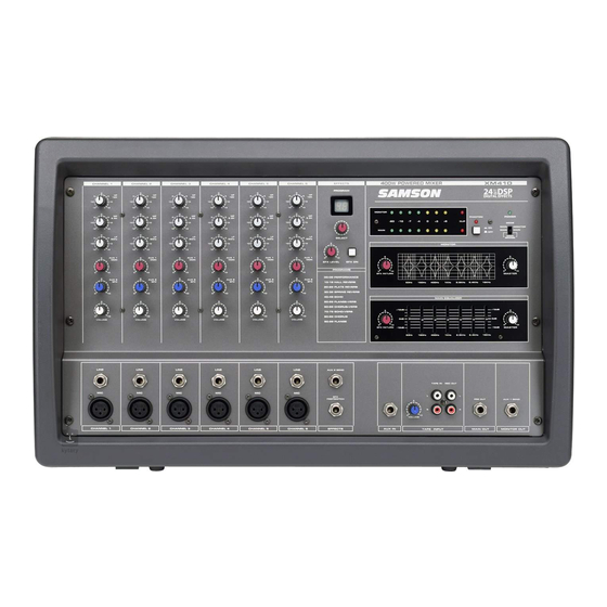
- Page 1 SIX CHANNEL POWERED MIXER WITH 24BIT DIGITAL EFFECTS...
- Page 2 XM410 is an ideal mixer and power amp solution offering big sound in a compact package. In these pages, you’ll find a detailed description of the features of the XM410 powered mixer, as well a descrip- tion of its front and rear panels, step-by-step instructions for its setup and use, and full specifications. You’ll also find a warranty card enclosed—please don’t forget to fill it out and mail it in so that you can receive...
- Page 3 XM410 Features The Samson XM410 Powered Mixer is a comprehensive, all-in-one mixer / power amplifier solution for live sound applications. Here are some of its main features: • Six channel powered mixer in ergonomically correct kickback enclosure allowing you to easily see and operate the front panel functions.
-
Page 4: Controls And Functions
Controls and Functions FRONT PANEL LAYOUT... - Page 5 MAIN+MONITOR. AUX 2 / EFX Effects Send The XM410 provides high quality, 24 Bit digital effects, and the level of effects can be set independently on each channel. The channel’s EFX (Effects) knob controls the amount of sig- nal that is sent to the EFX bus. The signal of the EFX bus is routed to the DSP EFX section for on-board signal processing.
-
Page 6: Bit Digital Effect Section
FRONT PANEL CONTROLS 24 BIT DIGITAL EFFECT SECTION The XM410 features a built-in, 24 Bit Digital Effects processor with 100 high quality, studio grade effects like Delay, Chorus and Reverb. The following section describes the features of the powerful on-board digital effects section: SELECT - Digital Effects Select Switch The SELECT switch allows you to pick one of the 100 built-in digital effects. -
Page 7: Main Monitor
POWER operating modes: CAUTION! SWITCHED OFF! Only change the power amp mode switch when the XM410’s power is MAIN-MONITOR With this setting, the MAIN and MONITOR sections can be used independently. The MAIN bus signal will be sent from the POWER AMP 2 jack, and the MONITOR bus signal will be sent from the POWER AMP 1 jack. -
Page 8: Main Section
Controls and Functions FRONT PANEL CONTROLS MAIN SECTION The XM410 has two internal power amplifiers and depending on the power amp MODE selec- tion switch, the amplifiers are sent the MAIN or MONITOR bus signal. The following section describes the MAIN bus operation, which allows... -
Page 9: Monitor Section
Controls and Functions FRONT PANEL CONTROLS MONITOR SECTION The XM410 has two internal power amplifiers and depending on the MODE selection switch, the amplifiers received their input signals from the MAIN or MONITOR bus. The following section describes the MONITOR bus opera-... -
Page 10: Xm410 Input And Output Connections
CHANNEL 1–6 MIC and LINE INPUTS The XM410’s six input channels each have a LINE level, Hi-Z (High Impedance) input and a MIC level, Low-Z (Low impedance) input. By using the PAD switches, you can connect a variety of signal sources from micro- phones to line level devices such as synthesizers, drum machines and direct boxes. -
Page 11: External Output Jacks
XM410 Input and Output Connections EXTERNAL OUTPUT JACKS The XM410 features several output connectors allowing you to interface a variety of external devices. A stereo recording device such as a cassette recorder can be connected to the REC OUT jacks, and additional power amplifiers can be connected to the MONITOR and MAIN output jacks. -
Page 12: Speaker Connection
There are three ways in which speakers can be connected to the XM410: A single speaker can be connected to the output jack of AMP 1 and AMP 2, two speakers can be connected in parallel to output jacks of AMP1 and AMP 2, or a single speaker can be connected to the BRIDGE jack (bridge connection). -
Page 13: Operating The Xm410
Operating the XM410 BASIC OPERATION The following section explains the basic operation of the XM410. CONNECTING MICROPHONES AND INSTRUMENTS 1. Before connecting mics or instruments, make sure that the power of all your systems components, including the XM410, is turned off. Also, make sure... -
Page 14: Using The Digital Effects
5. Now use the EFX RTN knob in the MAIN/MONITOR section to adjust the EFFECTS Return level. The EFX control is the overall level control for the DSP effects processor. If you are not using the XM410 in MAIN/ MONITOR or BRIDGE mode, be sure to raise the EFX RTN control up on both the MAIN and MAIN/ MONITOR sections so the level of effect is the same in both speakers. -
Page 15: Using An External Effect
MIC, LINE, TAPE IN and AUX inputs to a cas- sette deck, MD, DAT or any other type of recorder using the RECORD outputs. Simply connect the XM410’s REC OUT to the input jacks of the recorder as shown in the diagram above. -
Page 16: Xm410 System Set-Ups
XM410 System Set-Ups... - Page 17 XM410 System Set-Ups 16 16...
-
Page 18: Specifications
Specifications Specifications Rated Output power 200W/4Ω per amplifier Frequency response 20Hz~20KHz+/-0.5dB@1W Output into 8Ω (AMP OUT) 20 Hz~20KHz+/-0.4@+4dB Output into 10kΩ (MAIN OUT, MONITOR OUT, AUX 2 SEND) Total Harmonic Distortion Less than 0.06%@20Hz~20KHz, 75W output into4Ω (AMP OUT) Less than 0.1%@20 Hz~20KHz+14dB output into 10KΩ (MAIN OUT, MON OUT, AUX 2 SEND) + 4dB HUM &... - Page 19 Block Diagram/Synoptique/Blockdiagramm/Diagrama de bloques /Diagramma a Blocchi...