Table of Contents
Advertisement
Quick Links
625
WELLS BLOOMFIELD, LLC
2 ERIK CIRCLE, P. O. Box 280 Verdi, NV 89439
telephone: 775-689-5707
fax: 775-689-5976
www.wellsbloomfield.com
OWNERS MANUAL
for
DUAL
COFFEE BREWER
MODEL
8792
Includes:
Installation
Operation
Use & Care
Servicing Instructions
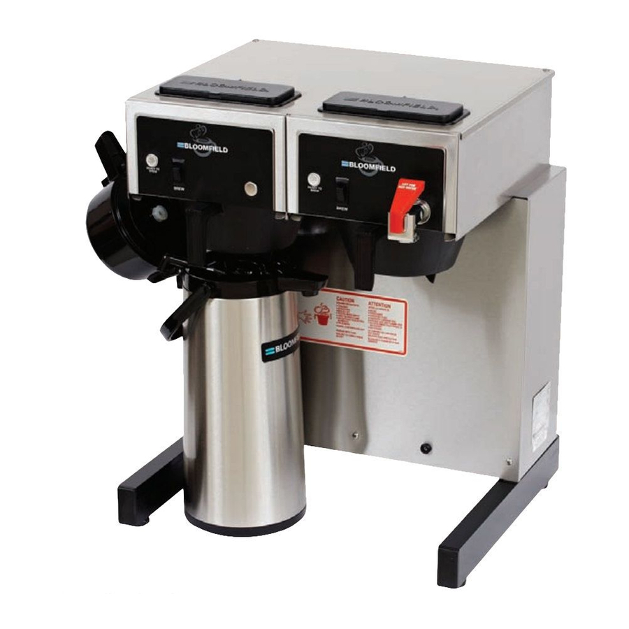
Model 8792 Brewer
with optional
7759 Airpots
PRINTED IN UNITED STATES OF AMERICA
75873
07
p/n
Rev. D ECN-13387
M625
1116 cps
Advertisement
Table of Contents

Related Manuals for Bloomfield GOURMET 1000 8792


Summary of Contents for Bloomfield GOURMET 1000 8792
- Page 1 WELLS BLOOMFIELD, LLC 2 ERIK CIRCLE, P. O. Box 280 Verdi, NV 89439 telephone: 775-689-5707 fax: 775-689-5976 www.wellsbloomfield.com OWNERS MANUAL DUAL COFFEE BREWER MODEL 8792 Includes: Installation Operation Use & Care Servicing Instructions Model 8792 Brewer with optional 7759 Airpots...
-
Page 2: Warranty Statement
It also does not apply if the serial nameplate has been removed or unauthorized service personnel perform service. The prices charged by Bloomfield Industries for its products are based upon the limitations in this warranty. obligation under this warranty is limited to the repair of defects without charge by a Bloomfield Authorized Service Agency or one of its sub-agencies. -
Page 3: Table Of Contents
EXPLODED VIEWS & PARTS LISTS WIRING DIAGRAMS MODEL VOLTS 8792 120/240 This manual applies to the following Wells Bloomfield Gourmet 1000™ products: 8792 with or without suffix Thank You for purchasing this Wells Bloomfield appliance. Proper installation, professional operation and consistent... -
Page 4: Features & Operating Controls
FEATURES AND OPERATING CONTROLS Fig. 1 Features & Operating Controls... -
Page 5: Precautions & General Information
WARNING: ELECTRIC SHOCK HAZARD All servicing requiring access to non-insulated components must be performed by qualified service personnel. Do not open any access panels which require the use of tools. Failure to heed this warning can result in electrical shock. WARNING: INJURY HAZARD All installation procedures must be performed by qualified personnel with full knowledge of all... -
Page 6: Installation Instructions
NOTE: Water supply inlet line must meet certain minimum criteria to insure successful operation of the brewer. Bloomfield recommends 1/4" copper tubing for installation of less than 12 feet and 3/8" for more than 12 feet from a 1/2" water supply line. - Page 7 NSF requires that the brewer be able to be moved for cleaning underneath. A flex line or loops of copper tubing will satisfy this requirement. See Figure 2 below. Fig. 2 Water Supply Installation In some areas, local codes require a backflow preventer (check valve) to be installed on the inlet water line.
-
Page 8: Operation
OPERATION Fig. 4 Brewer Operation Diagram IMPORTANT: Tanks must be full of water before connecting brewer to electrical power. Heating elements will be damaged if allowed to operate without being fully submerged in water. Damage caused by operating the brewer without water in the tanks is NOT COVERED BY WARRANTY. -
Page 9: Water Heater
WATER HEATER Water temperature is sensed by a thermobulb inserted into the water tank. This temperature signal is fed to the thermostat, which controls line power to the heating element. The setpoint temperature is adjustable at the thermostat. The element is protected from over- temperature by a hi-limit thermostat. -
Page 10: Brewing Coffee
Draw no more than one (1) cup of water at a time. A. PREPARATION Place one (1) genuine Bloomfield paper filter in the brew chamber. Add a pre-measured amount of fresh coffee grounds. Gently shake the brew chamber to level the bed of grounds. -
Page 11: Cleaning Instructions
PROCEDURE: Clean Coffee Brewer PRECAUTIONS: Disconnect brewer from electric power. Allow brewer to cool. FREQUENCY: Daily TOOLS: Mild Detergent, Clean Soft Cloth or Sponge Bristle Brush, Bottle Brush 1. Disconnect brewer from electric power. Allow brewer to cool before cleaning. 2. -
Page 12: Troubleshooting Suggestions
Be sure to add sufficient water (see pg. 6 START-UP) Increase water amount Adjust amount of grounds Adjust timer Use one (1) genuine Bloomfield filter per brew Thoroughly clean brew chamber Adjust coffee amount and grind Check/reinstall gasket on INSIDE of brew head... -
Page 13: Servicing Instructions
ACCESS PANELS TOP PANEL: Remove top panel to access hot water tank, thermostat, heating elements, brew circuit tubing, faucet valve and piping. Top panel is held by two screws at the rear and a retaining lip at the front. FRONT PANEL: Remove front panel to access timer, terminal block and solenoid. - Page 14 SERVICING INSTRUCTIONS (continued) CAUTION: SHOCK HAZARD These procedures involve exposed electrical circuits. These procedures are to be performed by qualified technical personnel only. NOTE: Optimum brewing temperature range is 195ºF to 205ºF (90ºC to 96ºC). IMPORTANT: A mechanical thermostat will maintain temperature within ±5ºF.
- Page 15 TIMER ADJUSTMENT The amount of water dispensed automatically during a brew cycle is controlled by the timer. Place empty decanter under brew chamber. Press BREW button. Brewer should dispense one decanter of water. To adjust amount: Remove brew chamber and button plug. Adjust knob on timer; clockwise increases time.
- Page 16 SERVICING INSTRUCTIONS (continued) IMPORTANT: When replacing heating element, also replace seal gaskets. Fig. 11 Remove Faucet Supply from Solenoid Fig. 12 Clean Strainer Screen REPLACE HEATING ELEMENT Remove tank lid assembly as described on page 13. Remove two hex nuts holding element to cover. Pull element from mounting holes.
- Page 17 REPLACE TIMER ASSEMBLY Unplug power cord or turn circuit breaker OFF. Remove front panel. Remove knob and three screws holding timer to bracket. Disconnect wiring to timer. Reassemble in reverse order. Adjust timer as described on page 13 REPLACE HOT WATER FAUCET COIL Symptom: Brewer drips continuously from brew head, except when faucet valve is turned OFF.
-
Page 18: Deliming Instructions
SERVICING INSTRUCTIONS (continued) CAUTION: CHEMICAL BURN HAZARD Deliming chemicals may be caustic. Wear appropriate protective gloves and goggles during this procedure. Never siphon deliming chemicals or solutions by mouth. This operation should only be performed by qualified and experienced service personnel. IMPORTANT: DO NOT spill, splash or pour water or deliming solution into or over any internal... - Page 19 Run at least three full brew cycles and discard all water generated. 12. Brewer is ready to use. SERVICING INSTRUCTIONS (continued) NOTE: Normally, silicone hoses do not need to be delimed. Should deliming hoses become necessary, Bloomfield recommends replacing the hoses.
-
Page 20: Exploded Views & Parts Lists
EXPLODED VIEW & PARTS LIST HOT WATER TANK ASSEMBLY ITEM PART NO. DESCRIPTION 8043-5 HOLD-DOWN STRAP 83457 NUT, HEX 8-32 KEPS 8512-51 THERMOSTAT (BLACK BODY - INCL. SEAL & MOUNTING SCREWS) 86280 THERMO (ALT) (GRAY BODY - INCL. TUBE & MOUNTING SCREWS) 8512-41 SEAL WASHER, THERMO CAP TUBE (ONLY) 8043-12... - Page 21 CABINET PLUMBING COMPONENTS TANK ASSY see PAGE 18 ITEM PART NO. DESCRIPTION 8540-3 FORMED TUBE, FAUCET OUTLET ASSEMBLY 10-7/8" LONG 8540-4 FORMED TUBE, FAUCET COIL INLET ASSEMBLY 8551-30 ADAPTER, 1/4" MALE FLARE x 1/8" FPT BRASS 8514-26 VALVE, FAUCET SHUT OFF, NEEDLE SEAT 85681 BRAIDED TUBE, FAUCET INLET 6MM x 299MM (11-3/4") LONG 8540-30...
-
Page 22: Electrical Components
EXPLODED VIEW & PARTS LIST (continued) ELECTRICAL COMPONENTS ITEM PART NO. DESCRIPTION 8707-55 SWITCH, MOMENTARY ROCKER, BREW 8718-31 INDICATOR, 120V, READY-TO-BREW 8718-1 TIMER, 2-MINUTE (WITH DIAL & KNOB) 120V 8552-18 TERMINAL BLOCK, 4P 85753 SOLENOID W/BYPASS, 120V, .50 GPM 85754 SOLENOID, SINGLE, 120V, .50 GPM 8512-51 THERMOSTAT (BLACK BODY - INCL. - Page 23 CABINET COMPONENTS ITEM PART NO. DESCRIPTION 8543-42 GASKET, SPRAY HEAD 82727 SPRAY DISK, EMBOSSED 8543-45 RETAINER, SPRAY HEAD (REQUIRES DRILL/RIVETS TO INSTALL) 8810-12 BUTTON PLUG, 1/2" DIA, PLASTIC (NON FAUCET MODELS) 8706-75 BUTTON PLUG, 2" DIA, METAL (TIMER) CAP, PLASTIC, LOWER SUPPORT SUPPORT, LOWER 81732 LEG ASSEMBLY, LEVELLING...
-
Page 24: Wiring Diagrams
WIRING DIAGRAM p/n 74810... - Page 25 NOTES...
- Page 26 Commercial Food Equipment Service Association Wells Bloomfield proudly supports CFESA Commercial Food Equipment Service Association SERVICE TRAINING - QUALITY SERVICE SERVICE TRAINING - QUALITY SERVICE Genuine Parts Protect - YOU - All - Ways CUSTOMER SATISFACTION CUSTOMER SATISFACTION WELLS BLOOMFIELD, LLC 2 ERIK CIRCLE, P.