Table of Contents
Advertisement
BLOOMFIELD INDUSTRIES
10 Sunnen Drive
St. Louis, MO 63143
telephone: 888-356-5362
fax: 314-781-2714
www.wellsbloomfield.com
75854
p/n 2M-
Rev. F
OWNERS MANUAL
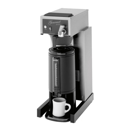
THERMAL SERVER
COFFEE BREWERS
8778
8783
8788
Servicing Instructions
Model 8780 Brewer
with optional
7750 Thermal Server
for
AIRPOT &
MODELS
8780
8782
8785
8786
Includes:
Installation
Use & Care
11
M622
0501
622
Advertisement
Table of Contents

Related Manuals for Bloomfield 8778


Summary of Contents for Bloomfield 8778
- Page 1 BLOOMFIELD INDUSTRIES 10 Sunnen Drive St. Louis, MO 63143 telephone: 888-356-5362 fax: 314-781-2714 www.wellsbloomfield.com OWNERS MANUAL AIRPOT & THERMAL SERVER COFFEE BREWERS MODELS 8778 8780 8782 8783 8785 8786 8788 Includes: Installation Use & Care Servicing Instructions Model 8780 Brewer...
-
Page 2: Warranty Statement
The prices charged by Wells Bloomfield for its products are installation or eighteen (18) months from the date of shipment based upon the limitations in this warranty. Seller’s obligation... -
Page 3: Table Of Contents
TABLE OF CONTENTS Thank You for purchasing this WARRANTY STATEMENT Wells Bloomfield appliance. SPECIFICATIONS Proper installation, professional FEATURES & OPERATING CONTROLS operation and consistent PRECAUTIONS & GENERAL INFORMATION maintenance of this appliance will AGENCY LISTING INFORMATION ensure that it gives you the very... -
Page 4: Features & Operating Controls
FEATURES AND OPERATING CONTROLS POUR-OVER COVER POUR-OVER OPENING “READY TO BREW” LIGHT BREW SWITCH HOT WATER FAUCET AIROT (BREWING POSITION) NOT AVAILABLE ON MODELS 8782 or 8785 IL1705 Fig. 1 Features & Operating Controls... -
Page 5: Precautions & General Information
PRECAUTIONS AND GENERAL INFORMATION WARNING: ELECTRIC SHOCK HAZARD All servicing requiring access to non-insulated components must be performed by qualified WARNING service personnel. Do not open any access panels which require the use of tools. Failure to heed this warning can result in electrical shock. WARNING: INJURY HAZARD All installation procedures must be performed by qualified personnel with full knowledge of... -
Page 6: Installation Instructions
(Use a low restriction type valve, operation of the brewer. such as a 1/4-turn ball valve, to avoid loss of water flow thru the Bloomfield recommends 1/4” valve. copper tubing for installation of NSF requires that the brewer be able to be moved for cleaning less than 25 feet and 3/8”... - Page 7 Models 8778, 8780, 8782, 8783 & 8785 (120V units) are brewer or result in decreased equipped with a cord and plug. They require a 115 - 125 volt performance.
-
Page 8: Operation
OPERATION IL1706 Fig. 4 Brewer Operation Diagram IMPORTANT: START-UP Tank must be full of For initial start-up, or if the brewer has not been used for an water before connecting extended period of time: brewer to electrical power. Be sure spray disk and brew gasket are properly installed in the Heating elements will be brew head. - Page 9 OPERATION (continued) WATER HEATER HI-LIMIT THERMOSTAT Water temperature is sensed by a thermobulb inserted into the water tank. This temperature signal is fed to the thermostat, which controls line power to the THERMOBULB heating element. The setpoint temperature is adjustable at the thermostat.
-
Page 10: Brewing Coffee
BREWING COFFEE CAUTION: A. PREPARATION Place one (1) genuine Bloomfield BURN HAZARD paper filter in the brew chamber. Exposed surfaces of the Add a pre-measured amount of brewer, brew chamber fresh coffee grounds. and airpot or server may Gently shake the brew chamber to be HOT to the touch, and level the bed of grounds. -
Page 11: Cleaning Instructions
CLEANING INSTRUCTIONS PROCEDURE: Clean Coffee Brewer CAUTION: BURN HAZARD PRECAUTIONS: Disconnect brewer from electric power. Allow brewer to cool. Brewing and serving temperatures of coffee are extremely hot. Hot coffee will FREQUENCY: Daily cause serious skin burns. TOOLS: Mild Detergent, Clean Soft Cloth or Sponge Bristle Brush, Bottle Brush CAUTION: SHOCK HAZARD... -
Page 12: Troubleshooting Suggestions
Coffee level too high or low Timer out of adjustment Adjust timer (automatic) Too many filter papers or wrong filter Use one (1) genuine Bloomfield paper filter per brew Brew chamber overflows Brew chamber dispense hole plugged Thoroughly clean brew chamber... -
Page 13: Servicing Instructions
SERVICING INSTRUCTIONS ACCESS PANELS CAUTION: TOP PANEL: SHOCK HAZARD Remove top panel to access hot water tank, thermostat, heating Opening access panels or elements, brew circuit tubing, faucet valve and piping. removing warmer plates on this Top panel is held by two screws at the rear and a retaining lip at brew may expose uninsulated the front. - Page 14 SERVICING INSTRUCTIONS (continued) TEMPERATURE ADJUSTMENT CAUTION: SHOCK HAZARD Unplug power cord or turn circuit breaker OFF. Remove top panel. These procedures involve exposed electrical circuits. Pull vent tube out of tank lid and insert a thermometer of known These procedures are to accuracy in vent hole.
- Page 15 SERVICING INSTRUCTIONS (continued) TIMER ADJUSTMENT IMPORTANT: Water pressure must be between 20 p.s.i and The amount of water dispensed automatically during a brew cycle 90 p.s.i. flowing pressure. is controlled by the timer. If water pressure exceeds this Place empty decanter under brew chamber. Press BREW value, or if water pressure button.
- Page 16 SERVICING INSTRUCTIONS (continued) IMPORTANT: When replacing REPLACE HEATING ELEMENT heating element, also replace Remove tank lid assembly as described on page 13. seal gaskets. Remove two hex nuts holding element to cover. Pull element from mounting holes. Reassemble in reverse order. REPLACE SOLENOID Symptom: Automatic brewer will not flow water;...
- Page 17 SERVICING INSTRUCTIONS (continued) REPLACE TIMER ASSEMBLY Unplug power cord or turn circuit breaker OFF. Remove front panel. Remove knob and three screws holding timer to bracket. Disconnect wiring to timer. Reassemble in reverse order. Adjust timer as described on page 13 REPLACE HOT WATER FAUCET COIL IMPORTANT: When replacing Symptom: Brewer drips continuously from brew head, except...
-
Page 18: Deliming Instructions
7. Set the tank back into the brewer. Reassemble the tank lid hoses become necessary, to the water tank. Make sure the gasket is properly in place, Bloomfield recommends and then reinstall the hold-down strap. replacing the hoses. 8. Reinstall wiring to heating element and thermostat. Reinstall the hi-limit thermostat (if removed). - Page 19 INCLUDES: MOUNTED THERMO, HI-LIMIT, 120V 1500W HEATING ELEMENT - NO HOT WATER COIL) DD-85575 INCLUDES: MOUNTED THERMO, HI-LIMIT, 120V 1800W HEATING ELEMENT & HOT WATER COIL) 8778, 8783, 8785 US WS-8541WF-300 INCLUDES: MOUNTED THERMO, HI-LIMIT, 120V 1500W HEATING ELEMENT & HOT WATER COIL)
-
Page 20: Exploded Views & Parts Lists
UK & EU 230V UNITS 2K-70101 TUBE, BASIN OUTLET/TANK INLET, SILICONE 2V-70102 TUBE, VENT, SILICONE 8780, 8782, 8786, 8788 2V-70398 TUBE, VENT, SILICONE LONG 8778, 8783, 8785 2K-70103 ELBOW, TANK OUTLET, SILICONE 2D-70095 BASIN PAN (AUTOMATIC) 8780, 8782, 8786, 8788 2D-70226 BASIN PAN (POUR-OVER) -
Page 21: Electrical Components
CORD & CAP ASSY UK (CE) 230UK UNITS 2E-70666 CORD & CAP EURO 3COND EU 230V UNITS 2K-70215 STRAIN RELIEF 8778, -80, -82, -83, -85 2K-70648 STRAIN RELIEF SMALL UK & EU 230V UNITS 2E-70709 TERMINAL BLOCK, 4P 8786, 8788 2E-75753 SOLENOID W/BYPASS, 120V, .50 GPM... - Page 22 EXPLODED VIEW & PARTS LIST (continued) CABINET COMPONENTS IL1711...
- Page 23 8780, 8782, 8786, 8788 Cap, Plastic, Lower Support Support, Lower 2A-71732 LEG ASSEMBLY, LEVELLING 2K-70229 BUSHING, HEYCO 2P-70272 Button Plug, 1/2" DIA PLASTIC (NON-FAUCET MODELS) 8778, 8783, 8785 A6-72288 BODY WRAP 8780 8780, 8778 A6-74813 BODY WRAP 8782 8782AF, 8785-A DD-74894 BODY WRAP...
-
Page 24: Wiring Diagrams
WIRING DIAGRAM 120VAC, POUR-OVER 1800 WATT MODELS” 8778 8783 8785 1500 WATT (Canadian) MODELS: 8778CA 8783CA 8785CA 120VAC, AUTOMATIC 1800 WATT MODELS” 8780 8782 8782XL 1500 WATT (Canadian) MODELS: 8780CA 8782CA 8782XLCA (BROWN 230V) BLACK 14 GA WHITE 14 GA... - Page 25 WIRING DIAGRAM (continued)
- Page 26 NOTES...
- Page 27 NOTES...
- Page 28 10 Sunnen Drive, St. Louis, MO 63143 telephone: 888-356-5362 fax: 314-781-2714 www.wellsbloomfield.com...