Advertisement
Advertisement
Table of Contents

Related Manuals for Audiolab 8200P


Summary of Contents for Audiolab 8200P
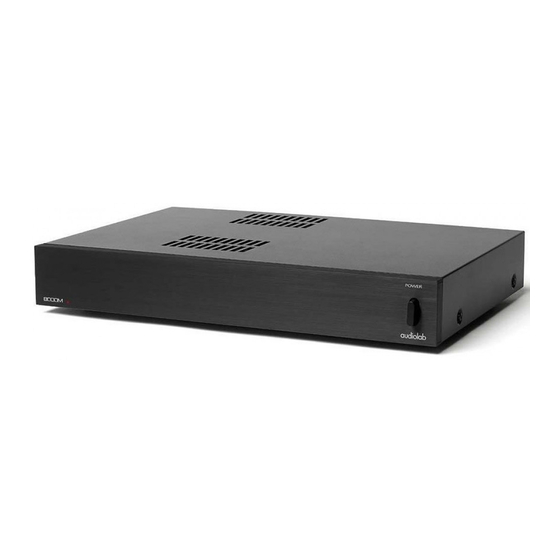
- Page 1 8200P...
- Page 2 VERSION HISTORY Date Update Content 2011.06.14 First Version 8200P...
-
Page 3: Table Of Contents
CONTENT Introduction Specification Assembly Sketch Schematic Diagram Wir ng Di gram Silk screen of Bottom 10-11 Maintenance Alignment Procedure Assembly Parts List 13-14 Electronic Parts List 15-19 8200P... -
Page 4: Introduction
This manual has been prepared with the greatest care, it is intended for information only and no liability shall be accepted for errors or changes to specification. For further service information, parts lists and updates, please contact our web-site at www.international audio group.com . 2011 International Audio Group Limited. All rights reserved. 8200P... -
Page 5: Specification
Within 1 dB Polarity (Phase) Non-Inverting Muting Muting controlled automatically Operating Temperature Range 10-35 °C Power Requirements(Depending on 50-60Hz 100V, 110-120V, and 220-230V models Region) available Maximum Power Consumption:500 VA Dimensions (W×H×D) 444×78×326mm Weight Net: 8.4 kg Shipping: 9.8 kg 8200P... -
Page 6: Assembly Sketch
ASSEMBLY SKETCH 8200P... -
Page 7: Schematic Diagram
SCHEMATIC DIAGRAM 8200P-Mainboard-P1/5 8200P... - Page 8 SCHEMATIC DIAGRAM 8200P-Mainboard-P2/5 8200P...
- Page 9 SCHEMATIC DIAGRAM 8200P-Mainboard-P3/5 8200P...
- Page 10 SCHEMATIC DIAGRAM 8200P-Mainboard-P4/5 8200P...
- Page 11 SCHEMATIC DIAGRAM 8200P-Mainboard-P5/5 8200P...
-
Page 12: Wir Ng Di Gram I A
WIRING DIAGRAM 8200P-Wiring Diagram-P1/1 8200P... -
Page 13: Silk Screen Of Top / Bottom
SILK SCREEN OF BOTTOM 8200P-MainBoard-Top Silkscreeen-P1/2 8200P... - Page 14 SILK SCREEN OF BOTTOM 8200P-MainBoard-Bottom Silkscreeen-P2/2 8200P...
-
Page 15: Maintenance Alignment Procedure
MAINTENANCE ALIGNMENT PROCEDURE 8200P -Bias Procedure And Ageing test step-P1/1 Audiolab 8200P Bias Procedure This procedure must only be carried out after the unit has passed a full functional test . 1.Connect the unit to be biased to mains and switch on. The mains voltage should be set to 230VAC ±... -
Page 16: Assembly Parts List
ASSEMBLY PARTS LIST 8200P-Assembly Bom-P1/2 PART NAME DESCRIPTION 300-1032410000R Front Panel finish and anodized aluminium Button Cap painted 215-1027410001R Power Button painted 215-1027410000R Mains Switch 305-1027410002R painted Bracket 500-3050240300AR M3 Ni 263-0020100102R 20*10*10mm EVA 309-1032410000R Chassis painted and silkscreen 588-3000066037R... - Page 17 ASSEMBLY PARTS LIST 8200P-Assembly Bom-P2/2 Remark:Colour Difference Table PART NAME DESCRIPTION 300-1032410000R screened, light grey(silver anodized) front panel 300-1032420000R screened, light grey(black anodized) 215-1027410001R silver painted,ABS757# button cap 215-1027420001R black painted,ABS757# 215-1027410000R silver painted,ABS757# power button 215-1027420000R black painted,ABS757# 309-1032410000R...
-
Page 18: Electronic Parts List
ELECTRONIC PARTS LIST 8200P-Electronic Bom-P1/5 PART NAME DISCRIPTION LOCATION 046-9400000400R 909 Terminal red/black 062-5118000201R Mains Cable 2 meter American SWITCH MAINS2P 041-1376000000QR Mains Switch SDDSA 3289A 071-1100000000R Tie Wrap 100MM YJ-100 MAINS INLET 2 POLE 2 044-1700000000QR Mains Inlet FUSE LOCS... - Page 19 ELECTRONIC PARTS LIST 8200P-Electronic Bom-P2/5 PART NAME DISCRIPTION LOCATION 27 001-1000205010QR Resistor 10R 1/4W 1% R135.136.235.236 28 001-1803205010QR Resistor 18K 1/4W 1% R108.208 29 001-1802205010QR Resistor 1K8 1/4W 1% R150.151.250.251 30 001-1004205010QR Resistor 100K 1/4W 1% R102.161.202.261.304 31 001-1005205010QR Resistor...
- Page 20 ELECTRONIC PARTS LIST 8200P-Electronic Bom-P3/5 PART NAME DISCRIPTION LOCATION 10000U/63V +50/-20% 66 006-1036508073QR Φ35*80 2U2 10% 50V MSK2 67 013-2250120505QR C121.122.221.222 WIMA 0U047 +80/-20% 25V 68 008-4703002517QR Transistor C118.220 69 018-3200653115R Transistor ZTX653 TO-92 Q115.215.304 70 018-3200753115R Transistor ZTX753 TO-92 Q116.216.306...
- Page 21 ELECTRONIC PARTS LIST 8200P-Electronic Bom-P4/5 PART NAME DISCRIPTION LOCATION 92 013-1010310507R Potentiometer 100pF 100V 5% C106.107.206.207 5K 25% BOURNS 93 020-5022121317R Insulation RV101.201 3329H-1-502LF Q121.122.221.222,Q123.1 94 324-0380250101QR Effect Transistor 38*25MM 24.223.224 2SK369GR TO-92 95 018-0500369115R 12 AWG WIRE TOSHIBA ("matched Q101.Q201...
- Page 22 ELECTRONIC PARTS LIST 8200P-Electronic Bom-P5/5 PART NAME DISCRIPTION LOCATION 120 306-1003770001QR Heat Sink1 anodized 121 306-1003770002QR Heat Sink2 anodized 122 306-1003770003QR Heat Sink3 anodized 123 306-1027410005R Heat Sink5 anodized,black 124 306-1027410003R Heat Sink anodized,black Connector Socket 125 812-1376000001R gilding Connector Socket...