
Related Manuals for Nakamichi SoundSpace 9


Summary of Contents for Nakamichi SoundSpace 9
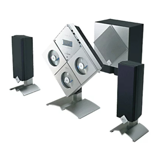
- Page 1 SS-9 General Service Manual Service Manual Stereo Music System SoundSpace 9 Random Memory Repeat Preset Disc Track Remaining Time Memory No. Vol. Loud.
- Page 2 SS-9 General GENERAL 1.1. Product Code Floor Stands (Option) D210 • Floor stand for Main Unit • Floor stand for Satellite Speakers L/R Abbreviations for Destinations: CAN — Canada — China 1.3. Cautions/Warnings — South America (1) Product Safety Notice —...
- Page 3 SS-9 General ADVERSEL: USYNLIG LASERSTRÅLING VED ÅBNING. CLASS 1 UNDGÅ UDSAETTELSE FOR STRÅLING. LASER PRODUCT VARO!: AVATTAESSA OLET ALTTIINA NÄKYMÄTTÖMÄLLE LAS- THIS COMPACT DISC PLAYER IS CLASSIFIED ERSÄTEILYLLE. AS A CLASS 1 LASER PRODUCT. ÄLÄ KATSO SÄTEESEEN. THE CLASS 1 LASER PRODUCT LABEL IS LOCATED ON THE REAR EXTERIOR.
- Page 4 SS-9 General 1.5. Package Ass’y and Accessory Ass’y (1) Main Unit Schematic Ref. No. Part No. Description Q'ty — Package & Accessory Ass'y (Main Unit) 0F05628A Carton Box 0F05630A Packing Bottom Center 0F05629A Packing Top Center — 0F05631A Accessory Box —...
- Page 5 SS-9 General (2) Subwoofer and Satellite Speakers Schematic Ref. No. Part No. Description Q'ty — Package and Accessory Ass’y (Subwoofer and Satellite Speakers) 0F05694A Carton Box S369 0F05703A Packing Bottom Subwoofer 0F05702A Packing Top Subwoofer 0F05691A Soft Sheet Subwoofer 0F05541A Soft Bag Satellite —...
- Page 6 SS-9 Main Unit Section Main Unit Main Unit Section Random Memory Repeat Preset Disc Track Remaining Time Memory No. Vol. Loud.
-
Page 7: Table Of Contents
SS-9 Main Unit Section CONTENTS REMOVAL PROCEDURES ..........................1-3 1.1. Rear Cover ............................. 1-3 1.2. Main P.C.B. Ass'y ..........................1-3 1.3. Mechanism CD Ass'y ..........................1-3 1.4. Front P.C.B. Ass'y ..........................1-4 1.5. Mechanism Chassis Block/Door Block of the Mechanism CD Ass'y ............ 1-4 1.6. -
Page 8: Removal Procedures
SS-9 Main Unit Section REMOVAL PROCEDURES NOTE: When parts required lubrication are replaced or reassembled, apply specified lubricant to the parts. For the parts which require lubrication, refer to 3. "MECHANISM ASS'Y AND PARTS LIST." 1.1. Rear Cover Refer to Fig. 1.1. (1) Remove F01 (Main Jack Cover) by pulling it out. -
Page 9: Front P.c.b. Ass'y
SS-9 Main Unit Section 1.4. Front P.C.B. Ass'y 1.5. Mechanism Chassis Block/Door Block of the Refer to Fig. 1.4. Mechanism CD Ass'y (1) Remove the Mechanism CD Ass'y. Refer to item 1.3. Refer to Fig. 1.5. (2) Remove screws F01 (BT2.6x6 + Flat Head, 2 pcs.) (1) Remove the Mechanism CD Ass'y. -
Page 10: Cd P.c.b. Ass'y And Traverse Mecha Ass'y
SS-9 Main Unit Section 1.7. CD P.C.B. Ass'y and Traverse Mecha Ass'y Refer to Figs. 1.7.1 and 1.7.2. Laser diode shorting lands (1) Remove the Mechanism Chassis Block. Refer to item 1.5. (2) Remove screws F01 (M3x5 + Binding (Black), 4 pcs.), F02 (Stabi SP) and F03, and detach F04 (Traverse Mechanism Block). -
Page 11: Laser Pickup
SS-9 Main Unit Section 1.8. Laser Pickup Short 1.8.1. Removing the Laser Pickup Refer to Fig. 1.8.1. (1) Remove the Traverse Mecha Ass'y. Refer to item 1.7. (2) Remove screws F01 (M1.7x4 + Pan, 2 pcs.) and F02 (M2.6x3.5 + Pan, 2 pcs.), and F03 (4 pcs.), and disas- semble F04 (Laser Pickup Block). - Page 12 SS-9 Main Unit Section How to reassemble the UD Cam S and UD Cam How to identify the UD Cam S and UD Cam: The UD Cam S is used on the left side of the CD Mecha- UD Cam S nism Ass'y in Fig.
-
Page 13: Electrical Checks
SS-9 Main Unit Section ELECTRICAL CHECKS Perform the following electrical checks for CD Players. 2.1. Measurement Instruments and Jigs (1) Oscilloscope (40 MHz or more) (2) DC Voltmeter (Digital Voltmeter) (3) ABEX Test Disc TCD-784 (DA09195A) (4) ABEX Test Disc TCD-726A (DA09204A) or TCD-725A 2.2. -
Page 14: Electrical Checks For Cd Player
SS-9 Main Unit Section 2.3. Electrical checks for CD Player Note: Do the same check for CD Player Nos. 1 to 3. STEP ITEM SIGNAL OUTPUT ADJUST- REMARKS SOURCE CONNECTION MENT Laser Current ABEX Test Disc DC Voltmeter — 1. Turn ON the power and load a test disc. Check TCD-784 across R101... - Page 15 SS-9 Main Unit Section STEP ITEM SIGNAL OUTPUT ADJUST- REMARKS SOURCE CONNECTION MENT Make sure that no noise nor track-jumping is found in Operation ABEX Test Disc — the following programs on the test disc. Check TCD-726 or TCD-725A To select the desired program, press Track Search button on the Main Unit or Remote Control •...
-
Page 16: Mechanism Ass'y And Parts List
SS-9 Main Unit Section MECHANISM ASS'Y AND PARTS LIST 3.1. Main Stand Ass'y Fig. 3.1 3.1. Main Stand Ass'y Schematic Ref. No. Part No. Description Q'ty — Main Stand Ass’y (Main Unit) 0J08792A Base Cushion Center S 0H08793B Stand Base Center R 0H08792B Stand Base Center L 0H08791D Base Joint 0H08796B Stand Pole... -
Page 17: Synthesis (Main Unit)
SS-9 Main Unit Section 3.2. Synthesis (Main Unit) Mechanism CD Ass'y 2 (A01) Mechanism CD Ass'y 1 (A01) 01 Fig. 3.2 1-12... - Page 18 SS-9 Main Unit Section 3.2. Synthesis Schematic Ref. No. Part No. Description Q'ty — Synthesis (Main Unit) — Mechanism CD Ass’y 1 — Mechanism CD Ass’y 2 0B85919A 2P Connector Ass’y (Except USA, CAN, TW) 0H08732A Dress panel 0H08733C Dress Plate (Except UK, EP) 0H09023A Dress plate RDS (UK, EP) 0H08739B Dress Plate Side A 0H08730A P Cap Button...
-
Page 19: Mechanism Cd Ass'y 1/Mechanism Cd Ass'y 2 (A01)
SS-9 Main Unit Section 3.3. Mechanism CD Ass'y 1/Mechanism CD Ass'y 2 (A01) Traverse Mecha Ass'y (B02) 12 Disc Loading Ass'y (B03) 07 Mechanism Chassis Ass'y (B01) 15 Fig. 3.3 1-14... - Page 20 SS-9 Main Unit Section 3.3. Mechanism CD Ass'y 1 (A01) 3.3. Mechanism CD Ass'y 2 (A01) Schematic Schematic Ref. No. Part No. Description Q'ty Ref. No. Part No. Description Q'ty — Mechanism CD Ass’y 1 — Mechanism CD Ass’y 2 HG08576A Door Cap Ass’y 2 (for Unit No.
- Page 21 SS-9 Main Unit Section 3.4. Mechanism Chassis Ass'y (B01) : Apply lubricant FL-955 : Apply lubricant G-4270 Approx. 10mm Lubricant: We suggest that you use FL- 955/G-4270 or equivalent type. Please contact: Kanto Chemicals Co. Ltd., 2- Approx. 10mm 7 Kanda Sakuma-cho, Chiyoda-Ku, Tokyo, Japan Fig.
-
Page 22: Traverse Mecha Ass'y (B02)
SS-9 Main Unit Section 3.5. Traverse Mecha Ass'y (B02) G-4270 : Apply lubricant G-4270. Apply G-4270: 05: Shafts (3 pcs.) 11: Shaft holes (2 places) G-4270 Lubricant: We suggest that you use G-4270 or equivalent type. Please contact: Kanto Chemicals Co. Ltd., 2-7 Kanda Sakuma-cho, Chiyoda- Ku, Tokyo, Japan Fig. -
Page 23: Disc Loading Ass'y (B03)
SS-9 Main Unit Section 3.6. Disc Loading Ass'y (B03) : Apply lubricant FL-955 Lubricant: We suggest that you use grease FL-955 or equivalent type. Please contact: Kanto Chemicals Co. Ltd., 2-7 Kanda Sakuma-cho, Chiyoda- Ku, Tokyo, Japan Fig. 3.6 1-18... - Page 24 SS-9 Main Unit Section 3.6. Disc Loading Ass'y (B03) Schematic Schematic Ref. No. Part No. Description Q'ty Ref. No. Part No. Description Q'ty CA09464A Loading Plate R SD S Ass’y CA09459A Disc Loading Ass’y 0C10191A Idler Pulley SL 0C10192A Pulley Fork SL BK10421A LED P.C.B.
-
Page 25: Electrical Parts List
SS-9 Main Unit Section ELECTRICAL PARTS LIST NOTES: 1. Abbreviations TR – Transistor, SID – Silicon Diode, ZD – Zener Diode, Varicap – Variable Capacitance Diode RK – Carbon Resistor, RM – Metal Film Resistor, RF – Fail Safe Type Resistor, RC –... -
Page 26: Cd P.c.b. Ass'y
SS-9 Main Unit Section Schematic 4.4. LED P.C.B. Ass'y Ref. No. Part No. Description Schematic LCD701 0B90913B LCD DLC-A1622P Ref. No. Part No. Description LED701 0B12806A LED Green BK10421A LED P.C.B. Ass’y LED702 0B12806A LED Green LED703 0B12806A LED Green LED1 0B12900A LED BLUE LED704... -
Page 27: Ic Block Diagrams
SS-9 Main Unit Section IC BLOCK DIAGRAMS µ • System Controller (U502 PD78F4225GC-8) Pin No. Signal Name Function Active Standby — Grounded. MASTER Remote controller's Main/Remote detect signal. — H.PIN Headphone connection detect signal. — AVss — GND. INH1 LCD/LED display inhibit signal. LCE1 Chip enable signal to the LCD driver. - Page 28 SS-9 Main Unit Section µ • System Controller-Continued (U502 PD78F4225GC-8) Pin No. Signal Name Function Active Standby — Not used. ENCDMU-M Main room muting permit output signal from the CD. ENCDMU-R Remote room muting permit output signal from the CD. MUTE-M Main room muting output.
- Page 29 SS-9 Main Unit Section µ • Mechanism Controller (U501 PD78018FGC) Pin No. Signal Name Function Active Standby LSI DATA DSP command data output. LSI CLK DSP command clock output. LSI XLT DSP command latch pulse output. SCLK DSP servo parameter readout clock. CDRST DSP reset output.
- Page 30 SS-9 Main Unit Section µ • Mechanism Controller-Continued (U501 PD78018FGC) Pin No. Signal Name Function Active Standby AVss — GND. — (For testing, etc.) — (For testing, etc.) — Not used. BSENS Battery voltage sensing input. — ASENS ACC voltage sensing input. —...
- Page 31 SS-9 Main Unit Section RCOM1 LCOM1 LCOM1 RCOM1 LCOM2 RCOM2 LCOM2 RCOM2 LCOM3 RCOM3 LCOM4 RCOM4 RCOM3 LCOM3 LEVEL SHIFT LEVEL SHIFT LATCH LATCH CONTROL CONTROL SHIFT REGISTER SHIFT REGISTER Function Switch LC78211 (U201, 202) Function Switch LC78213 (U204) DATA OUT IN OUT IN LATCH...
- Page 32 SS-9 Main Unit Section DATA LEVEL SHIFT BASS+ BASS+ BASS— BASS— TREBLE— TREBLE— CODE DETECTOR TREBLE+ TREBLE+ CIRCUIT Electronic Tone Controller TC9184AP (U208) NC 2 27 NC L-OUT 3 26 R-OUT NC 4 50K‰ / 25 NC 91STEP 24 R-IN L-IN 5 SAME AS FOR L-CH...
- Page 33 SS-9 Main Unit Section POWVCC2 VO3(–) VO3(+) VO4(–) VO4(+) PREVCC OPIN4(+) OPIN4(–) OPOUT4 OPIN3(+) OPIN3(–) OPOUT3 STBY2 + – + – STANDBY – – – + – LEVEL – SHIFT LEVEL – SHIFT LEVEL – SHIFT LEVEL – SHIFT STANDBY + –...
- Page 34 SS-9 Main Unit Section 2 VCC 7 VS CIRCUIT STANDBY CIRCUIT OUT1 OUT2 THERMAL SHUT-OFF 5 GND Motor Driver TA8409F (U105, 106) 24 RFI 23 MT 22 TON 21 CP 20 CC2 19 CC1 18 CB MIRR PEAK/BOT HOLD RF M DFCT 7.5K LD ON...
- Page 35 SS-9 Main Unit Section 35 DO MPU INTERFACE EMPHA 25 CSFLAG C BIT Pa,Pb DETECTOR DETECTOR 26 F0/P0/C0 AUDIO 27 F1/P1/C1 DISEL 28 F2/P2/C2 DOUT fs CALCULATOR 29 VF/P3/C3 DIN0 32 AUTO 33 BPSYNC DATA INPUT LOCK 34 ERROR DIN1 DEMODULATOR DETECTOR 16 DATAO...
- Page 36 SS-9 Main Unit Section DAC BLOCK TES1 TEST CLOCK ERROR XRST GENERATOR CORRECTOR RMUT SERIAL— IN RFAC DEMODULATOR INTERFACE INTERFACE LMUT ASYI ASYMMETRY XTAI TIMING ASYO OVER SAMPLING CORRECTOR LOGIC DIGITAL FILTER XTAO BIAS 3rd—ORDER XPCK NOISE SHAPER SUB CODE FILO DIGITAL PROCESSOR...
-
Page 37: Block Diagram
SS-9 Main Unit Section BLOCK DIAGRAM Fig. 6 1-32... - Page 38 SS-9 Subwoofer Section Subwoofer Subwoofer Section...
- Page 39 SS-9 Subwoofer Section CONTENTS ELECTRICAL ADJUSTMENTS .........................2-2 1.2. Adjustment Procedure ...........................2-3 MECHANISM ASS'Y AND PARTS LIST ......................2-4 2.1. Synthesis (Subwoofer) ...........................2-4 2.2. PA Chassis Ass'y (A01) ........................2-5 ELECTRICAL PARTS LIST ..........................2-6 3.1. AMP P.C.B. Ass'y ..........................2-6 3.2. REM P.C.B. Ass'y ..........................2-6 3.3.
-
Page 40: Adjustment Procedure
SS-9 Subwoofer Section 1.2. Adjustment Procedure STEP ITEM SIGNAL OUTPUT ADJUST- REMARKS SOURCE CONNECTION MENT Preparation — — — 1. Insert shorting plugs into input L/R jacks on the Subwoofer unit. 2. Remove the PA Chassis. 3. Turn ON the power of the Subwoofer unit and allow 15 minutes before starting adjustment. -
Page 41: Mechanism Ass'y And Parts List
SS-9 Subwoofer Section MECHANISM ASS'Y AND PARTS LIST 2.1. Synthesis (Subwoofer) 04 (A01) PA Chassis Ass'y Fig. 2.1 2.1. Subwoofer Synthesis Schematic Ref. No. Part No. Description Q'ty — Synthesis (Subwoofer) CB00729A Subwoofer Grille Ass’y CB00627A Subwoofer Speaker S800L05 0H08368D Power Amp Cover —... -
Page 42: Pa Chassis Ass'y (A01)
SS-9 Subwoofer Section 2.2. PA Chassis Ass'y (A01) Fig. 2.2 2.2. PA Chassis Ass'y (A01) Schematic Schematic Ref. No. Part No. Description Q'ty Ref. No. Part No. Description Q'ty BK10338A T.SEC P.C.B. Ass’y CE — PA Chassis Ass’y (Subwoofer) (UK, AUS, EP, CH, HK, KR) BK10339A T.SEC P.C.B. -
Page 43: Electrical Parts List
SS-9 Subwoofer Section ELECTRICAL PARTS LIST NOTES: 1. Abbreviations TR – Transistor, SID – Silicon Diode, ZD – Zener Diode, Varicap – Variable Capacitance Diode RK – Carbon Resistor, RM – Metal Film Resistor, RF – Fail Safe Type Resistor, RC –... -
Page 44: Ps P.c.b. Ass'y
SS-9 Subwoofer Section 3.4. PS P.C.B. Ass'y 3.8. T.SEC P.C.B. Ass'y Schematic Schematic Ref. No. Part No. Description Ref. No. Part No. Description BK10329A PS P.C.B. Ass’y BK10338A T.SEC P.C.B. Ass’y CE (UK, AUS, EP, CH, HK, D401,402 0B10520A GBU6D D403,404 0B12836A SID 1SR35-400A BK10339A T.SEC P.C.B. - Page 45 SS-9 Satellite Speaker Section Satellite Speaker Satellite Speaker Section...
- Page 46 SS-9 Satellite Speaker Section CONTENTS MECHANISM ASS'Y AND PARTS LIST ......................3-2 1.1. Satellite Ass'y (Front/Rear) ........................3-2 SPECIFICATIONS (See the end of this manual.) MECHANISM ASS'Y AND PARTS LIST 1.1. Satellite Ass'y (Front/Rear) Fig. 1.1 1.1. Satellite Ass'y (Front/Rear) Schematic Ref.
- Page 47 SS-9 Specifications SPECIFICATIONS CD Player Section Outputs (SONY TYPE-3) (1 kHz, 0 dB) Rec Output Level ........2.0 V ± 2 dB (Tr. No. 1) Total Harmonic Distortion + Noise (SONY TYPE-3) 1 kHz 0 dB ..........Less than 0.006% (Tr. No. 1) Frequency Response (SONY TYPE-3) 20 Hz - 20 kHz ........
- Page 48 SS-9 Specifications AM Tuner Section [Standard Test Condition (S.T.C.)] RF input levels are given by Loop Antenna, 90 dB/m Modulation ..........30% mod., 400 Hz RF Frequency ........U.S.A. Band - 1000 kHz Europe Band - 999 kHz Tuning Range ........USA, CAN 530 kHz - 1710 kHz 10 kHz step 531 kHz - 1602 kHz 9 kHz step 522 kHz - 1629 kHz 9 kHz step Usable Sensitivity (S/N = 20 dB) ....
- Page 49 SS-9 Specifications Output (Input 200 mV) 1 kHz ........200 mV ± 2 dB Remote 1 kHz ........200 mV ± 2 dB Rec Out Maximum Output Level 1% THD ..........More than 7 V Power Amplifier Section [Standard Test Condition (S.T.C.)] Signal ............
- Page 50 SS-9 Specifications OTR model ........... AC110-120/220-240V 50/60 Hz JPN model ..........AC100V 50/60 Hz Power Consumption ........280 W max. Dimensions* Main unit ..........523 (W) × 523 (H) × 115 (D) mm 20-5/8 (W) × 20-5/8 (H) × 4-1/2 (D) inches Main Unit (with tabletop stand) .....
- Page 51 Template × 1 * Dimensions do not include protruding parts. Height is the panel height. • Specifications and design are subject to change for further improvement without notice. Nakamichi Corporation 1-153 Suzukicho, Kodaira, Tokyo 187-8501, Japan Phone: 81 (42) 342-1111 Nakamichi America...
- Page 52 SS-9 SS-9 Main Unit Section - Main P.C.B. Ass’y (1/4) SS-9 SS-9...
- Page 53 SS-9 SS-9 Main Unit Section - CD P.C.B. Ass’y (2/4) SS-9 SS-9...
- Page 54 SS-9 SS-9 Main Unit Section - Front P.C.B. Ass’y (3/4) SS-9 SS-9...
- Page 55 SS-9 SS-9 Subwoofer Section (4/4) SS-9 SS-9...