
Related Manuals for Trane GETB


Summary of Contents for Trane GETB
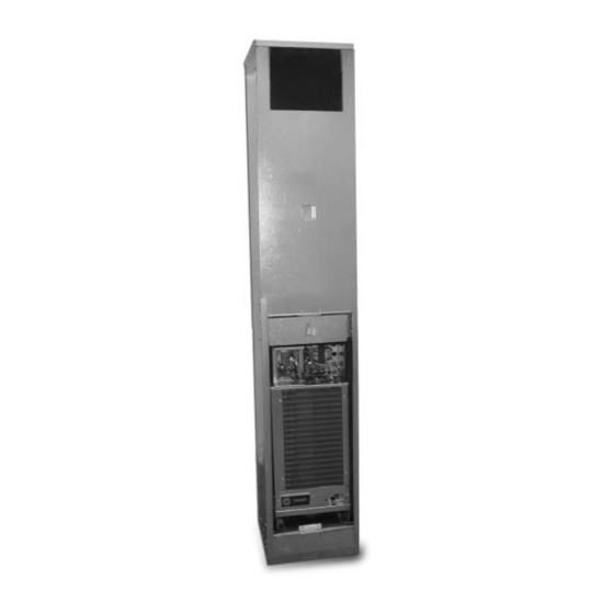
- Page 1 Installation Owner Diagnostics Vertical Stack Water-Source Heat Pump Model GETB Models “A” and later Design Sequence GETB – 009-036 60 HZ – 009-036 50 HZ February 2006 WSHP-SVN08B-EN...
- Page 2 Responsible Refrigerant Practices! Trane believes that responsible refrigerant practices are important to the environment, our customers, and the air conditioning industry. All technicians who handle refrigerants must be certified. The Federal Clean Air Act (Section 608) sets forth the requirements for handling, reclaiming, recovering and recycling of certain refrigerants and the equipment that is used in these service procedures.
-
Page 3: Table Of Contents
WSHP-SVN08B-EN Contents Installation/Startup/Commissioning Pre-installation Checklist General Information Dimensions/Weights Installation Instructions Electrical Requirements Pre-Startup Checklist Startup/Commissioning Sequence of Operation Operating Pressures Startup Checklist & Log Maintenance Warranty Information Troubleshooting Checklist Unit Wiring... -
Page 4: Installation/Startup/Commissioning
Pre-installation Checklist WARNING Fiberglass Wool! Product contains fiberglass wool. Disturbing the insulation in this product during installation, maintenance or repair will expose you to airborne particles of glass wool fibers and ceramic fibers known to the state of California to cause cancer through inhalation. Glass wool fibers may also cause respiratory, skin or eye irritation. -
Page 5: General Information
Units containing the Deluxe 24V con- trol design will incorporate a micro- processor-based control board. The Trane microprocessor board is factory wired to a terminal strip to provide all necessary terminals for field connec- tion. The deluxe board is equipped... -
Page 6: Dimensions/Weights
Table 1: Unit weights Shipping Shipping Size Weight Weight with pallet (lb) w/o pallet (lb) Cabinet Chassis ALLOW 36" (914 mm) AT UNIT FRONT FOR CHASSIS REMOVAL Figure 1: Mechanical clearances Dimensions/Weights/ Clearance WARNING Improper Unit Lift! Test lift unit approximately 24 inches to verify proper center of gravity lift point. - Page 7 BE ON THE SAME SIDE OF THE UNIT. 1/2" (12.7) O.D. ELECTRIC CONDUIT 1" (25.4) RISER LOCATION CAN BE ON ANY SIDE EXCEPT FRONT, AND MAY BE SUPPLIED BY TRANE OR BY OTHERS. RISER CONNECTION 1/2” (13) NPTE = 009-018 3/4” (19) NPTE = 024,036 NOTE:...
- Page 8 Return Air (hinged) Acoustical Door The hinged acoustical door is recessed into the wall so that the door is flush with the surface of the wall. The opening through the wall for the door assembly must be centered with the return-air opening of the unit cabinet.
-
Page 9: Installation Instructions
WSHP-SVN08B-EN Installation General Installation Checks The checklist below is a summary of the steps required to successfully in- stall a unit. This checklist is intended to acquaint the installing personnel with procedures required in the installation process. It does not replace the de- tailed instructions called out in the ap- plicable sections of this manual. - Page 10 For vibration isolation, it is recom- mended that flexible steel braided hoses be installed instead of hard pip- ing between the vertical risers and the unit chassis. Trane offers 4-types of hose kit varia- tions: • Stainless steel braided flexible hose with manual shut-off (ball) valves •...
- Page 11 Field Installed Power Wiring Power wiring to the equipment must conform to National and Local Electric Codes (NEC) by a professional electri- cian. WARNING Live Electrical Components! During installation, testing, ser- vicing and troubleshooting of this product, it may be necessary to work with live electrical compo- nents.
- Page 12 Drywall Installation Before installing drywall around cabi- net. Cover the cabinet supply and re- turn openings with plastic or cardboard to help prevent dust or con- struction debris from reaching unit components. Warranties will be void- ed if paint or foreign debris is allowed to contaminate internal unit compo- nents.
- Page 13 1 Secure the door frame to the side studs using the holes located in the door frame and field provided screws, Figure 6. Figure 6: Door opening Note: If the gap between the door frame, and the side stud is over 1/16- inch, place a shim in between the door frame and the stud to prevent the door frame from bending/denting.
- Page 14 WARNING Live Electrical Components! During installation, testing, ser- vicing and troubleshooting of this product, it may be necessary to work with live electrical compo- nents. Have a qualified licensed electrician or other individual who has been properly trained in handling live electrical compo- nents perform these tasks.
- Page 15 Using Antifreeze In areas of the country where entering water temperatures drop below 45°F or where piping is being run through areas subject to freezing, the loop must be freeze protected by using an approved antifreeze solution to pre- vent the earth loop water from freez- ing inside the heat exchanger.
- Page 16 Low Voltage Wiring Factory ordered thermostats and zone sensors are pre-wired with a quick connecting plug. 1 After installing the cabinet assem- bly, simply plug the male portion of thermostat/zone sensor plug into the female portion of the plug locat- ed inside the unit’s junction box.
- Page 17 Blower Motor Speed Retrofit Motors installed in the unit have mul- tiple speed configurations. To modify the rpm of the motor, the following steps may be followed. WARNING Hazardous Voltage! Disconnect all electric power, in- cluding remote disconnects and discharge motor start/run capaci- tors before servicing.
-
Page 18: Electrical Requirements
Table F2: Blower External Static Pressure with Return Air Door (RAD), with filter Speed Model No. Ducted GET009 High GET009 GET009 High GET009 GET012 High GET012 GET012 High GET012 GET015 High GET015 GET015 High GET015 GET018 High GET018 GET018 High GET018 GET024 High... -
Page 19: Pre-Startup Checklist
Pre-Start-up Checklist Before energizing the unit, the following system devices must be checked: ____ Is the high voltage power supply correct and in accordance with the nameplate ratings? ____ Is the field wiring and circuit protection the correct size? ____ Is the low voltage control circuit wiring correct per the unit wiring diagram? ____ Is the piping system clean/complete and correct? (A recommendation of all system flushing of debris from the water-to-refrigerant heat exchanger, along with air purging from the water-to-refrigerant heat exchanger be done in accordance with the Closed-Loop/Ground Source Heat Pump Systems Installation Guide). -
Page 20: Startup/Commissioning
Initial Unit Start-up Start-up with deluxe controls is included below: Note: Start-up for the Tracer ZN510 controller may be found in WSHP-IOP-2. WARNING Live Electrical Components! During installation, testing, servicing and troubleshooting of this product, it may be necessary to work with live electrical components. -
Page 21: Operating Pressures
Table OP-1: Operating Pressures GENERAL: There are many variables (airflow, air temperatures) in an air conditioning system that will affect operating re- frigerant pressures and temperatures. The chart below shows approximate conditions and is based on air flow at the rated SCFM, entering air at 80.6 °FDB, 66.2 °FWB in cooling, 68 °FDB in heating. - Page 22 Table OP-1: Operating Pressures Entering Water Model Water Flow Pressure, Temp, °F GET 018 GET 018 GET 018 GET 018 GET 018 GET 018 GET 018 GET 018 GET 018 GET 018 GET 018 GET 018 GET 018 GET 018 GET 024 GET 024 GET 024...
- Page 23 Water Pressure Drop Table 7 should be used to define feet of head/pressure drop. Note: To calculate feet of head, when using gauges that read in PSIG, multiply PSI by 2.31. Table 7: Water pressure drops (WPD) in feet of head Cooling Unit Size Ft.
-
Page 24: Startup Checklist & Log
Use this form to thoroughly check-out the system and units before and during start- Installing Contractor: up. (This form need not be returned to the factory unless requested during technical service support). Job Name: Model Number: Date: Serial Number: In order to minimize troubleshooting and costly system failures, complete the following checks and data entries before the system is put into full operation. -
Page 25: Maintenance
WSHP-SVN08B-EN Maintenance Preventive Maintenance Maintenance on the unit is simplified with the following preventive sugges- tions: Filter maintenance must be performed to assure proper operation of the equipment. Filters should be inspect- ed at least every three months, and re- placed when it is evident they are dirty. -
Page 26: Warranty Information
Warranty Information Standard Warranty The standard water-source heat pump warranty is Trane’s parts-only warranty, running 12-months from star- tup, not to exceed 18-months from shipment. Extended Warranty The optional extended warranty is a second through fifth year warranty. The time starts at the end of standard 1-year coverage through the fifth year. -
Page 27: Troubleshooting
WSHP-SVN08B-EN Troubleshooting WARNING Hazardous Service Procedures! The maintenance and trouble shooting procedures recommend- ed in this section of the manual could result in exposure to electri- cal, mechanical or other potential safety hazards. Always refer to the safety warnings provided throughout this manual concern- ing these procedures. -
Page 28: Troubleshooting Checklist
Problem No response to any thermostat setting Unit short cycles Blower runs, but compressor does not Insufficient capacity High pressure switch open High head pressure Low suction pressure Troubleshooting Checklist Heating Cooling Cause Main power off Defective control transformer Broken or loose connection Defective thermostat Transformer Thermostat or sensor improperly located... -
Page 29: Unit Wiring
AND/OR DASHED DEVICE OUTLINES INDICATE COMPONENTS PROVIDED BY THE FIELD. PHANTOM LINE ENCLOSURES INDICATE ALTERNATE CIRCUITRY OR AVAILABLE SALES OPTIONS. INDICATE WIRING BY TRANE CO. NUMBERS ALONG THE RIGHT SIDE OF THE SCHEMATIC DESIGNATE THE LOCATION OF BY LINE NUMBER. AN UNDERLINED... - Page 30 Unit Wiring Deluxe Diagram 208V-50/60 Hz-1PH WSHP-SVN08B-EN...
- Page 31 Unit Wiring ZN510 Diagram 230V-50/60 Hz-1PH WSHP-SVN08B-EN...
- Page 32 For more information, contact your local district office or e-mail us at comfort@trane.com Literature Order Number WSHP-SVN08B-EN File Number SV-UN-WSHP-SVN08B-EN-0206 Supersedes SV-UN-WSHP-SVN08A-EN-1105 Stocking Location Inland Trane has a policy of continuous product and data improvement and reserves the right to change design and specifications without notice.