Table of Contents
Advertisement
Advertisement
Table of Contents

Related Manuals for NBE RTB PHOENIX v16.0


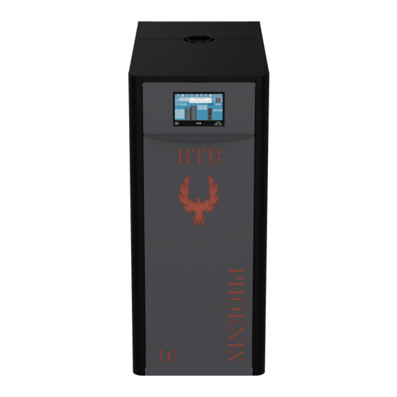
Summary of Contents for NBE RTB PHOENIX v16.0
- Page 1 TRÆPILLESYSTE RTB - ready to burn...
- Page 2 Dear Customer. Thank you for purchasing this NBE product which is designed and manufactured to the highest standards in the EU. In order for you to get the most out of your product, we strongly recommend that you carefully read this manual prior to installation and operation of the equipment.
- Page 3 New updated manuals can be downloaded from www.nbe-global.com Open top covers etc. with extreme caution. When the boiler is in operation, there is a risk of high temperature below the top covers, which can cause burns.
- Page 4 TECHNICAL DATA: RTB PHOENIX BOILERS Exhaust Fan with under pressure control NBE V16 printboard with wifi module Air compressor cleaning system (boiler) 7” capacitive O2 sensor touch screen Air compressor tank with air pressure sensor 10-100% stepless modulating Air compressor...
- Page 5 TECHNICAL DATA: RTB PHOENIX BOILERS Product Name RTB 10 RTB 16 RTB 30 RTB 50 RTB 80 Design Model Phoenix Phoenix Phoenix Phoenix Phoenix Nominal Performance 11 kW 17 kW 25 kW 48 kW 78kW Minimum Performance 3 kW 5,5 kW 7,5 kW 14 kW 23 kW...
- Page 6 RTB 10-30 Phoenix RTB 10-30 Phoenix RTB 10-30 Phoenix *kilo capacity will vary depending on the density of the pellets Double KIT for Product Name 80x80 hopper 80x80 Extension NBE hopper 80x80 300087 300085 300069 Compatible w/ All boilers 80x80...
- Page 7 BULK FEEDING: Our auger and vacuum feeds systems makes it easy to provide bulk storage and feeding of wood pellets to the boiler. Below you will find several examples on how to configure bulk feeding: Large hopper 3,3-7,6 ton with 3 meter auger. Large hopper, 3,3-7,6 ton with vacuum transport to RTB Phoenix hopper.
- Page 8 BOILER ROOM DESIGN: The boiler room for biomass boilers must be installed in accordance with the rules set forth by your local building codes, en vironmental authorities, and labor inspectorate. If you are in doubt on how to set up your boiler room, we recommend that you contact you r local certified RTB dealer for guidance.
- Page 9 BOILER ROOM DESIGN: The internal diameter of the chimney must be sufficient enough for the amount of flue gasses the chimney has to lead away. If the internal diameter is too small, this will prevent the smoke from exiting fast enough due to the large resistance in the chimney. This could cause the smoke to turn back;...
- Page 10 BOILER ROOM DESIGN: 8. Fuel. The pellets must be pure wood, 6-8 mm, max. 8 % water. Materials with glue, paint, wood paint or plastics shall not be burned. If the fuel storage is greater than 0,75 m3, the boiler system and fuel storage must be located in a separate fire cell with at least one BD30 door to the other room.
- Page 11 INSTALLATION DIAGRAMS: A properly executed installation ensures that the system functions properly. Both national/local guidelines and requirements must always be observed. The boiler can be installed on a pressurized system up to max 2.5 bar. 1. Simple Return water control with mechanical flow via adjustable shunt.
- Page 12 4. Weather Compensation and solar thermal heating for the DHW tank . With an NBE flow box and 3-way weather compensation vlave, the controller is able to control the minimum boiler return temperature on the system and adjust...
- Page 13 A properly executed installation ensures that the system functions properly. Both national/local guidelines and requirements must always be observed. The boiler can be installed on a pressurized system up to max 2.5 bar. 5. NBE CASCADE Cascade systems are ideal when achieving...
- Page 14 INSTALLATION OF THE BOILER: General Guidelines 1. The boiler should only be installed by qualified installers with a ”Certificate for installation and service of small biofuel plant” and must be installed according to your local and national building and construction codes. 2.
- Page 15 FIRST TIME START-UP: Installation and operation of the hopper level sensor Your RTB Phoenix boiler includes a lazer distance sensor that allows you to monitor the pellet level in your hopper. Installation: Find the laser distance sensor at the back of the boiler. If you are using a RTB Phoenix hopper, string the lazer distance sensor through the precut hole found in the back of the hopper.
- Page 16 V16 PRINT: 10 11 12 13 14 18 50 69 37 38 39 - 100-230 V power supply 12 pin BURNERPRINT Air flow sensor...
- Page 17 V16 PRINT CONNECTIONS Main Print Board 12 pin cable WIRE INPUTS OUTPUTS NUMBER FUNCTION 100V-240V PE-N-L 1-2-3 100-240 Volt 50-60Hz THERM C-C2 7-8-9 Safety Thermostat MOTOR PE-N-L1 4-5-6 External Auger BURNER Green/Yelllow BURNER WHITE BURNER YELLOW Blower BURNER GREEN Internal auger BURNER BLUE Igniter...
- Page 18 12 PIN BURNER PRINT CONNECTIONS RTB Phoenix 10-30 kW 12 pin BURNER PRINT WIRE INPUTS OUTPUTS FUNCTION SKU: MOTOR BLACK MOTOR WHITE Internal Auger Motor YN60 8RPM, SKU: 400020-180 MOTOR MOTOR CAP BLACK Capacitor MOTOR CAP BLACK BLOWER Green/Yelllow PE (grounded on motor) BLOWER BLACK Combustion Blower...
- Page 19 12 PIN PRINT CONNECTIONS RTB Phoenix 50 kW 12 pin BURNER PRINT WIRE INPUTS OUTPUTS FUNCTION SKU: MOTOR BLACK MOTOR WHITE Internal Auger Motor Gear motor YN70 RPM, SKU: 400022-180 MOTOR MOTOR CAP BLACK Capacitor Capacitor 1.8μF, SKU: 400031 MOTOR CAP BLACK BLOWER Green/Yelllow...
- Page 20 CONNECTING TO THE INTERNET: Connecting your burner via the web: 1. On your controller go to SETTINGS/COMMUNICATION/NETWORK and find your internet Router 2. Go to PASSWORD and enter the password for your router. Your controller will now be connected to the internet. Creating an account on Stokercloud 3.
- Page 21 CONNECTING TO THE INTERNET: 6. Enter where you live and save location. Once your configuration are saved, you will now have your own webpage and system dashboard on Stokercloud. After a short period of time you will see data streaming from the burner.
- Page 22 - If necessary, NBE will contact you by e-mail and ask your permission to make operational change. - NBE evaluates your graphs and the patterns of your burner, and makes adjustments based on the observations. - Changes to your settings can always be viewed via your system LOG.
- Page 23 SERVICE MAINTENANCE Cleaning should be carried out as needed. There is a big difference depending on the construction setup, adjustments and wood pellet quality on how often maintenance should be performed. The maintenance table below is only an indication of the type of maintenance required and applies only for RTB Phoenix systems! When 7 days...
- Page 24 TROUBLESHOOTING: We have collected the most typical solutions to small problems. Problem. Possible cause. Possible solution. Alarm hot drop shaft. Cinders in the burner head. More air for combustion. Cause must be identified. Back pressure in the boiler. Clean the boiler etc. Contact your dealer No draft in the chimney.
- Page 25 Replace the fuse to a new one. Safety thermostat not active. Reconnect by firmly pressing the red button. The controller has been overvoltage. Send controller to NBE for repair. The burner deactivate residual current protection Electric ignition is faulty. Change the electric ignition to a new.
- Page 26 PREVENTING FLUE GAS CONDENSATION: When a boiler has an extremely high efficiency >93 %, the temperature of the flue gas is naturally low. Typical flue loss is only 2-3 %. This creates greater demands on your chimney and on how to adapt the boiler to its existing installation. It is important, if you have condensation to prevent it;...
- Page 27 STOKERCLOUD MENU: Weather data is automatically retrieved if the controller is online and registered at www.stokercloud.dk. Output icons show the operational status of the equipment. You can choose which parameters you would like to track on the dashboard by going to System Menus/Screen Selecting an output icon shows more detailed information.
- Page 28 Submenus can be found when accessing a main menu. Select to retrieve parameter help text.
- Page 29 Under boiler timer you can choose between ON, OFF, or nightime reduction temperature. Under the DHW time you can choose between On/Off during a timer period.
- Page 30 Select to view weather data graphs. Choose graph periods upto 48 hours Choose color of line graph Choose data to graph. The blue bar graph shows DHW consumption. Green= heat consumption...
- Page 31 Displays setting changes Displays changes in operations status Provides info messages . Weather Compensation Data...
- Page 32 Returns are only made by agreement with NBE. To the extent that NBE is liable to the purchaser, NBE’s liability is limited only to direct loss and not to damages incurred by connected equipment and / or indirect damage, loss of earnings, operating losses, connection costs, etc.
- Page 34 ACCESSORIES: The controller supports the following accessories. Extension module for V13 and V16 Wifi Temperature Sensor: controller (SKU:300211) (SKU: 300042) Get additional 7 outputs and Battery powered wireless inputs for additional equipment. temperature senor that can be used as a reference sensor for weather compensation, domestic hot water, or as an external stop temperature reference.
- Page 35 WIRING DIAGRAM...
- Page 36 INSTALLING MOTOR VALVE WITH 12 PIN PLUG (Connect on 230 Volt AC) On available output L12 – L16 or on Ext Mod U14-U20) 1. Mount the 3-way valve on the flow from the boiler. 2. AB flow into the valve. 3.
- Page 37 Quick Installation Guide Pelvac Vacuum Transport System with rotary valves SKU: 708100, 707100 Put overpressure back into the top of the storage unit.. Failure to do so may cause the auger to jam Wire Wire Color Connection to print Vacuum/Rotary Valve Green/Yellow Vacuum/Rotary Valve Blue...
- Page 38 Installation Guide Pelvac Vacuum Transport System with rotary valves SKU: 708100, 707100 Under Vacuum Transport Menu: Specify Outputs for Vacuum/Rotary valve and External(Extraction )Auger in the controller Specify Maximum Distance (i.e. distance from the sensor when the vacuum will start) and Minimum Distance (i.e distance from the sensor when the vacuum should stop) .
- Page 39 INSTALLING CERAMIC HEATING ELEMENT 300 W. 12 pin BURNER PRINT WIRE INPUTS OUTPUTS FUNCTION SKU: IGNTION BLUE Ceramic heating element 250Watt, SKU : Igniter 400305 IGNITION BROWN Recommended adjustments: • Preheating 30 sek. • Power 65 % • Max time 6 min.
- Page 40 ¾” valve 570022 1” valve 570023 ¾” w/ weather compensation KIT 570024 1” w/ weather compensation KIT 570026 NBE ¾” weather compensation KIT w/ flowbox 510027 NBE 1” weather compensation KIT w/ flowbox 510028 Size ¾” 1” Settings The picture on right shows the starting point of the dial.
- Page 41 NBE 3-way valve Installation of temp sensor On the main printboard choose an available input between T2-T10. Or, on the extension print choose an available input port fra T11 - T18. Connection to printboard: As an outdoor reference: mount the sensor outside on the Ref.
- Page 42 NOTES: Date Date Weighing Weighing kW low kW low kW high kW high Blower low Blower low Blower middle Blower middle Blower high Blower high Comments: Comments: Date Date Weighing Weighing kW low kW low kW high kW high Blower low Blower low Blower middle Blower middle...
- Page 43 NOTES: Date Date Weighing Weighing kW low kW low kW high kW high Blower low Blower low Blower middle Blower middle Blower high Blower high Comments: Comments: Date Date Weighing Weighing kW low kW low kW high kW high Blower low Blower low Blower middle Blower middle...