
Related Manuals for UNI-T UT70D


Summary of Contents for UNI-T UT70D
-
Page 1: Table Of Contents
Table of Contents Title Page Overview Unpacking Inspection Safety Information Rules For Safe Operation International Electrical Symbols The Meter Structure Rotary Switch Functional Buttons Display Symbols Measurement Ranges Selecting a Measurement Range Manual Ranging and Autoranging Measurement Operation AC Voltage Measurement DC Voltage Measurement DC Milivolt Measurement Measuring Resistance / Conductance,... - Page 2 DC Current G. AC Current Frequency & Duty Cycle Maintenance General Service Testing the Fuses Replacing the Battery Replacing the Fuses RS232C Serial Port RS232C Port Cable Setting of RS232C Serial Ports System Requirements for Installing the UT70D Interface Program...
-
Page 3: Overview
This Operating Manual covers information on safety and cautions. Please read the relevant information carefully and observe all the Warnings and Notes strictly. Warning To avoid electric shock or personal injury, read the "Safety Information" and "Rules for Safe Operation" carefully before using the Meter. -
Page 4: Unpacking Inspection
Open the package case and take out the Meter. Check the following items carefully to see any missing or damaged part: Item Description English Operating Manual 1 piece Test Lead 1 pair Test Clip 1 piece 9V Battery (NEDA 1604,6F22 1 piece or 006P) (installed) RS232C Interface Cable... -
Page 5: Safety Information
Safety Information CE Version: The Meter complies with the standards IEC61010-1:in pollution degree 2, overvoltage category CAT III 1000V, CAT IV 600V and double insulation . UL Version: The Meter complies with the standards UL61010B-1, in pollution degree 2, overvoltage category CAT II 1000V and double insulation. -
Page 6: Rules For Safe Operation
Rules For Safe Operation(1) Warning To avoid possible electric shock or personal injury, and to avoid possible damage to the Meter or to the equipment under test, adhere to the following rules: Before using the Meter inspect the case. Do not use the Meter if it is damaged or the case (or part of the case) is removed. - Page 7 Rules For Safe Operation(2) Before measuring current, check the Meter's fuses and turn off power to the circuit before connecting the Meter to the circuit. Replace the battery as soon as the battery indicator appears. With a low battery, the Meter might produce false readings that can lead to electric shock and personal injury.
-
Page 8: International Electrical Symbols
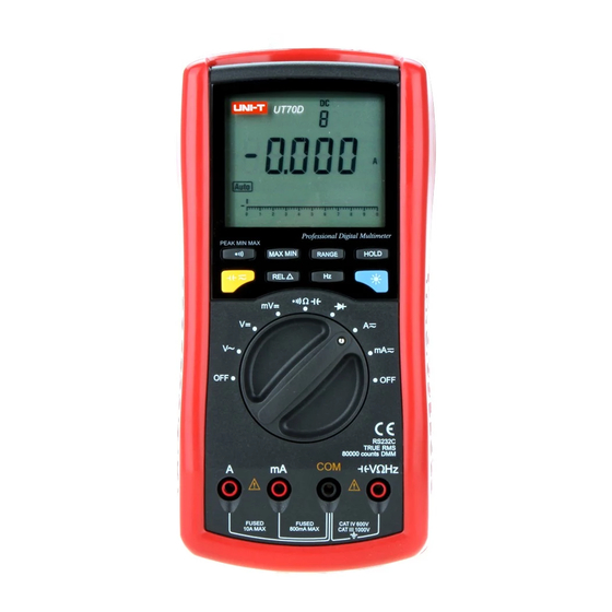
The Meter Structure (see figure 1) -
Page 9: Rotary Switch
Rotary Switch Below table indicated for information about the rotary switch positions. Continuity measurement. Capacitance measurement. measurement. AC or DC current measurement range from 0.1mA to 10.000A. AC or DC current measurement range from 0.001mA to 800.00mA. -
Page 10: Functional Buttons
Functional Buttons(1) Below table indicated for information about the functional button operations. Function Symbol Turn the continuity buzzer on and Continuity off in the Resistance measurement Test mode. Press while turning on the Power-Up Meter to disable the beeper Option of pressing any button. - Page 11 Functional Buttons(2) Function Symbol Press HOLD down to enter the DATA Data holding HOLD Auto Hold mode at any mode.t Press HOLD to switch between HOLD resistance and conductance value Others at conductance or resistance measuring mode. l Press to select capacitance test at measurement position.
-
Page 12: Display Symbols
Display Symbols(1) (see figure 2) Meaning No. Symbol... -
Page 14: Measurement Ranges
Measurement Ranges(1) A measurement range determine the highest value the Meter can measure. Most Meter functions have more than one range. See "Accuracy Specifications". A. Selecting a Measurement Range Being in the right measurement range is important: If the range is too low for the input, the Meter displays to indicate an overload. - Page 15 Measurement Ranges(2) Press RANGE. The Meter enters the manual range mode and turns off. Each presses of RANGE increments the range. When the highest range is reached, the Meter wraps to the lowest range. To exit the manual range mode, press and hold RANGE for over 1 seconds.
-
Page 16: Measurement Operation
When AC voltage measurement has been completed, disconnect the connection between the testing leads and the circuit under test, and remove the testing leads away from the input terminals of the Meter. -
Page 17: Dc Voltage Measurement
To avoid harms to you or damages to the Meter from electric shock, please do not attempt to measure voltages higher than 1000V though the reading may be obtained. The DC voltage ranges are: 8.0000V, 80.000V, 800.00V and 1000.0V. To measure DC Voltage, connect the Meter as follows: When DC voltage measurement has been completed, disconnect the connection between the testing leads... -
Page 18: Dc Milivolt Measurement
To avoid harms to you or damages to the Meter from electric shock, please do not attempt to measure voltages higher than 1000V though the reading may be obtained. The DC Millivolt ranges are: 80.000mV, 800.00mV. To measure DC Voltage, connect the Meter as follows: In this range, the Meter has an input impedance higher than 4000M When DC mV voltage measurement has been... -
Page 19: Measuring Resistance / Conductance, Capacitance And Continuity
Measuring Resistance / Conductance, Capacitance & Continuity To avoid damages to the Meter or to the devices under test, disconnect circuit power and discharge all the high-voltage capacitors before measuring resistance, capacitance & continuity. Use the DC voltage function to confirm that the capacitor is discharged. - Page 20 Note The test leads can add 0.1 to 0.2 of error to resistance measurement. To obtain precision readings in low-resistance measurement, that is the range of 800.00 , short-circuit the input terminals beforehand, using the relative measurement function button REL to automatically subtract the value measured when the testing leads are short-circuit from the reading.
- Page 21 Continuity Measurement (see figure 7) To measure the continuity, connect the Meter as follows: Insert the red test lead into the terminal and the black test lead into the COM terminal. Set the rotary switch to and press select measurement mode. The buzzer sounds if the resistance of a circuit under test is less than 100 The LCD displays...
- Page 22 Capacitance Measurement (see figure 8) The Meter's capacitance ranges are: 1.000nF, 10.00nF, 100.0nF, 1.000 F, 10.00 F, and 100.0 F. To measure capacitance, connect the Meter as follows: Insert the red test lead into the terminal and the black test lead or test clip into the COM terminal. Set the rotary switch to and press button...
-
Page 23: Testing Diodes
E. Testing Diodes (see figure 9) To avoid damages to the Meter or to the devices under test, disconnect circuit power and discharge all the high-voltage capacitors before measuring diodes. Use the diode test to check diodes, transistors, and other semiconductor devices. -
Page 24: Dc Or Ac Current Measurement
depending on the resistance of other pathways between the probe tips. Connect the test leads to the proper terminals as said above to avoid error display. The LCD will display indicating open-circuit for wrong polarity connection. The unit of diode is Volt (V), displaying the positive -connection voltage-drop value. - Page 25 The current measurement has 2 measurement positions on the rotary switch: A and mA The A has a 8.0000A and 10.000A range, with autoranging;the mA has a 80.000mA and 800.00mA range, with auto ranging. To measure current, connect the Meter as follows: Turn off power to the circuit.
-
Page 26: Frequency & Duty Cycle Measurement
G. Frequency & Duty Cycle Measurement (see figure 11) Frequency measurement The measurement ranges are: 1kHz, 10kHz, 100kHz and 1MHz. The maximum measurement range is 1MHz. To measure frequency, connect the Meter as follows: Insert the red test lead into the terminal and the black test lead into the COM terminal. - Page 27 The attenuate amplitude of signal is different from different measuring positions and ranges, therefore the required input amplitude is different when measuring frequency at different measuring positions and ranges. Although it is possible to select frequency and duty cycle measurement mode at resistance, continuity and diodes ranges, these functions cannot be used.
- Page 28 measuring frequency at different measuring positions and ranges. Although it is possible to select frequency and duty cycle measurement mode at resistance, continuity and diodes ranges, these functions cannot be used. It is recommended to use DCV 8V range. The polarity of trigger slope is positive. When duty cycle measurement has been completed, disconnect the connection between the testing leads and the circuit under test, and remove the testing...
-
Page 29: Max/Min Recording Mode
MAX MIN Recording Mode(1) (see figure 12) MAX/MIN recording mode applied to all measurement function except at conductance measurement function. MAX/MIN recording mode captures and stores the maximum and minimum input value detected, and calculates a running average of all readings taken. In the MAX/MIN mode, when the Meter detects an input that is below the recorded minimum or above the recorded maximum, the Meter beeps and records the new minimum... - Page 30 MAX MIN Recording Mode(2) Make sure that the Meter is in the desired measurement function and range. Press MAX/MIN to enter MAX/MIN recording mode. The present reading is displayed, and the Meter is locked in the present range, and Enter the REC is displayed.
-
Page 31: Peak Max/Min Mode
Peak Test PEAK MAX MIN mode is an additional function of Pressing to toggle between 100ms response time and 1ms response time. This function can only be enabled when the Meter is under MAX/MIN, HOLD mode. To enter PEAK MAX MIN mode: Press to enter PEAK MAX MIN mode (1ms response time), it steps through the sequence of MAX and MIN reading only. -
Page 32: Operation Of Hold Mode
Operation of Hold Mode To avoid possibility of electric shock, do not use HOLD mode to determine if circuits are without power. The HOLD mode will not capture unstable or noisy readings. The HOLD mode is applicable to all measurement functions. -
Page 33: The Use Of Relative Value And Relative Percentage Value Mode
The use of Relative Value and Relative Percentage Value Mode The and % mode applies to all measurement functions, with auto ranging.REL mode can be used together with AUTO-HOLD and MAX/MIN mode. The definition is as follows: Relative value ( )=present value - stored value. For instance, if the stored value is 20.0V and the present value is 22.0V, the reading would be 2.0V. -
Page 34: Turning On The Display Backlight
Turning on the Display Backlight... -
Page 36: General Specifications
Maximum Voltage between Terminals and Grounding :1A,250V fast type glass fuse, 5x20mm. :10A,250V fast type glass fuse, 5x20mm. CE Version: IEC61010 CAT III 1000V, CAT IV 600V overvoltage and double insulation standard. UL Version:UL 61010B-1, CAT II 1000V overvoltage double insulation standard. This meter is suitable for indoor use. -
Page 37: Accuracy Specifications
Overload 40 ~ 50Hz Protection 50 ~ 60Hz 60 ~ 400Hz (0.8%+60)* (1.5%+60)* 800.00mV (0.8%+40)** (1.5%+40)** 1000V DC/AC 8.0000V 100 V (0.8%+20) (1.5%+20) 80.000V continuous. 10mV 800.00V 100mV 1000.0V Remarks: Input impedance Displays True RMS value. Frequency response: 40 ~ 400Hz * When input signal 8mV. -
Page 38: Conductance Test
C. Resistance, Conductance & Continuity Test 800.00 0.01 (0.3%+60) 8.0000k 80.000k (0.3%+40) 800.00k 600Vp 8.0000M (0.5%+20) 80.000M (2%+20) 80.000nS 0.001nS (2%+120) Continuity Test 0.01 Remarks: Continuity Test Range: Buzzer beeps continuously. Open circuit voltage approximate 0.7V. At 800.00 ~ 80.000M Range: Open circuit voltage approximate 0.7V. -
Page 39: Dc Current
Remarks: Open circuit voltage approximate 3V. Displays approximate forward voltage drop reading. F. DC Current 80.000mA 1A,250V fast type (0.2%+40) glass fuse, 5x20mm. 10 A 800.00mA 8.0000A 100 A 10A,250V fast type (0.3%+40) glass fuse, 5x20mm. 10.000A Remarks: At 8A & 10A Range: For continuous measurement 10 seconds and interval time between 2 measurements greater... -
Page 40: Frequency & Duty Cycle
Frequency response 40Hz ~ 400Hz. Displays True RMS value. 600Vp 600Vp 1A,250V fast type glass fuse, 5x20mm. 10A,250V fast type glass fuse, 5x20mm. - Page 41 Duty Cycle 600Vp (1% ~ 99%)
-
Page 42: Maintenance
MAINTENANCE(1) This section provides basic maintenance information including battery and fuse replacement instruction. Warning Do not attempt to repair or service your Meter unless you are qualified to do so and have the relevant calibration, performance test, and service information. To avoid electrical shock or damage to the Meter, do not get water inside the case. -
Page 43: Testing The Fuses
MAINTENANCE(2) -
Page 44: Replacing The Battery
MAINTENANCE(3) -
Page 45: Replacing The Fuses
MAINTENANCE(4) D. Replacing the Fuses (see figure 14) Warning To avoid electrical shock or arc blast, or personal injury or damage to the Meter, use specified fuses ONLY in accordance with the following procedure. To replace the Meter's fuse: Turn the Meter to OFF position and remove all connections from the terminals. -
Page 46: Rs232C Serial Port
B. Setting of RS232C Serial Ports (see figure 15) -
Page 47: System Requirements For Installing The Ut70D Interface Program
RS232C Serial Port(2) System Requirements for Installing the UT70D Interface Program To use UT70D Interface Program, you need the following hardware and software: An IBM PC or equivalent computer with 80586 or higher processor and 640 x 480 pixel or better monitor. - Page 48 CCopyright 2002 Uni-Trend International Limited. All rights reserved. Manufacturer: UNI-TREND TECHNOLOGY(DONG GUAN)LIMITED Address: Dong Fang Da Dao, Bei Shan Dong Fang Industrial Development District, Hu Men Town, Dong Guan City, Guang Dong Province, China Headquarters: Uni-Trend International Limited Address: Rm901, 9/F, Nanyang Plaza 57 Hung To Road Kwun Tong Kowloon, Hong Kong Tel: (852) 2950 9168 Fax: (852) 2950 9303...