Advertisement
Quick Links
P/N:110401108881X
UT203+/UT204+
AC/DC Clamp Meters
User Manual
Preface
Thank you for purchasing the new clamp meter. In order to use this
product safely and correctly, please read this manual thoroughly,
especially the Safety Instruction part.
After reading this manual, it is recommended to keep the manual at
an easily accessible place, preferably close to the device, for future
reference.
Limited warranty and liability
Uni-Trend guarantees that the product is free from any defect in material
and workmanship within one year from the purchase date. This warranty
does not apply to damages caused by accident, negligence, misuse,
modification, contamination and improper handling. The dealer shall
not be entitled to give any other warranty on behalf of Uni-Trend. If
you need warranty service within the warranty period, please contact
your seller directly.
Uni-Trend will not be responsible for any special, indirect, incidental
or subsequent damage or loss caused by using this device. As some
countries or regions do not allow limitations on implied warranties and
incidental or subsequent damages, the above limitation of liability may
not apply to you.
1. Overview
The UT203+/UT204+ are portable true RMS AC/DC clamp meters
with automatic range. They are designed according to EN61010-1
CAT II 600V/CAT III 300V safety standards, and come with full-function
protection which ensures users a safe and reliable measurement
experience. Aside from basic measurement functions, they also have
high precision current scale and high voltage frequency measurement
extension. UT204+ also comes with live/neutral wire detection. These
meters are great tools for electrical measurements up to 1000A current.
2. Features
True RMS measurement
Audio visual NCV electric field detection
High voltage frequency range: 10Hz~60kHz; low voltage frequency
range: 60Hz~10MHz
UT203+ AC/DC current range: 40A, 400A, frequency response:
45Hz~400Hz
UT204+ AC/DC current range: 60A, 600A, frequency response:
45Hz~400Hz, live/neutral wire detection
ACA/DCA mode memory function for current measurement
Large capacitance (UT203+: 40mF, UT204+: 60mF) and temperature
measurement (U 204+)
T
Large LCD and fast refresh rate (3 times/s), capacitance measurement
response time:
≤1mF: less than 3s; ≤10mF: about 6s; ≤60mF: about 8s
Full-function false detecting protection for up to 600V (3.6kVA)
energy surge; overvoltage and overcurrent alarm
The power consumption without backlight is about 1.8 mA. The
circuit has an automatic power saving function. The consumption
in sleep state is <11uA, which effectively extends the battery life to
400 hours.
Please read the safety and warning parts in this manual
thoroughly.
Caution: Please read the safety instructions carefully before use.
3. Standard Accessories
Open the package and check the below items, if any is missing or
damaged, please contact your supplier immediately:
User manual ----------------------- 1 pc
Test leads --------------------------- 1 pair
K-type temperature probe ------ 1 pc (Only UT204+)
Cloth bag ---------------------------- 1 pc
4. Safety Instructions
The meter is designed according to EN61010-1, 61010-2-032/033
and electromagnetic radiation protection EN61326-1 safety standards,
and conforms to double insulation, CAT II 600V, CAT III 300V and
pollution grade II. In case the meter is not used properly as instructions,
the protection provided may be weakened or lost.
Do not use the tester or test leads if they appear to be damaged.
Do not use the meter if the rear or battery cover is open.
Keep fingers behind finger guard and do not touch the live parts to
prevent electric shock.
The function switch should be correctly set before measurement.
It is forbidden to switch scale during measurement or damage may
occur!
Do not apply AC/DC voltage over 600V to any terminal to prevent
electric shock or damage.
Use caution to avoid shock hazard when working with voltages
above DC 60V, or AC 30Vrms.
Never input voltage or current which exceeds the specified limit.
Maximum range should be selected if measured value is unknown.
Before measuring resistance, diode and continuity, please disconnect
all power and fully discharge all capacitors to avoid inaccuracy.
When the "
" symbol appears on the LCD, please replace the
batteries in time to ensure measurement accuracy. Batteries should
be removed If the meter is long-term idle.
Do not change the internal circuit of the meter to avoid damage to
the meter and user!
Do not expose the meter in high temperature/humidity, flammable,
explosive or intense magnetic environments.
Clean the meter casing with a soft cloth and mild detergent.
Do not use abrasives or solvents!
5. Symbols
Symbol
Description
Caution, possibility of electric shock
Alternating current
Direct current
Equipment protected throughout by double insulation
or reinforced insulation
Earth (ground) terminal
Warning or caution
6. General Specifications
Max LCD display counts: 4099 (U 203+), 6099 (U 204+)
T
T
Polarity display: Auto
Overload display: "OL" or "- OL"
Low battery indication: "
" means low battery
Low battery shutdown prompt: The "Lo.bt" interface appears on LCD
and lasts for about 10s, the buzzer beeps 3 times, and the meter
automatically shuts down.
Test position error: If the source under test is not placed at the center
of the clamp jaws when measuring current, ±1.0% additional error in
reading may be produced.
Drop protection: 1m
The maximum size of jaw opening: 28mm in diameter
Battery: AAA 1.5V battery × 2
Auto power off (adjustable): The meter will auto power off if there is no
operation for 15 min.
Dimensions: 215mm × 63.5mm × 36mm
Weight: About 235g (including batteries)
Altitude: 2000m
Operating temperature and humidity: 0°C~30°C (≤80%RH), 30°C~40°C
(≤75%RH), 40°C~50°C (≤45%RH)
Storage temperature and humidity: -20°C~+60°C (≤80%RH)
Electromagnetic compatibility: RF=1V/m, overall accuracy=specified
accuracy+5% of range; RF>1V/m, no specified calculation
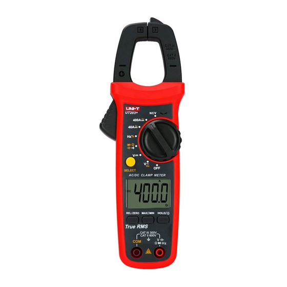
7. External Structure (Picture 1)
1) NCV sensing end
2) Clamp jaws
3) Hand guard
4) LED indicator
5) Jaw opening trigger
6) Function scale knob
7) LCD display
8) Function buttons
9) Signal input jack (red and positive +)
10)COM input jack (black and negative -)
Picture 1
8. Button Description
SELECT Button
In composite scale, press this button to switch between the corresponding
functions or ranges;
HOLD/BACKLIGHT Button
Short press this button to enter/exit the data hold mode, and long press
(about 2s) this button to turn on/off the backlight.
MAX/MIN Button
(valid for ACV/DCV, ACA/DCA, "C/"F, resistance and capacitance scales)
Short press this button to enter the maximum/minimum measurement mode
and long press this button to exit.
REL Button
(valid for ACV/DCV, DCA, "C/"F and capacitance scales).
Press this button to store the current reading as a reference for future
readings. When the LCD display value is reset to zero, the stored reading
will be subtracted from the future readings. Press this button again to exit
the relative value mode.
9.Operating Instructions
9.1 AC/DC Current Measurement (Picture 2)
Select the corresponding current range.
Press the trigger to open the clamp jaws, and fully enclose one conductor.
Only one conductor can be measured at a time, or the measurement
reading will be wrong.
Caution:
Do not insert the testing leads during current measurement to avoid
electric shock.
The current measurement must be taken with safeguard protection.
Press the REL button to return to zero before the DC current measurement,
and meanwhile the center hole of jaw should be perpendicular to the
current direction to ensure accuracy.
The open circuit zeroing reading may be relatively large after (high) DC
current measurement. Please perform the AC current detection again to
counteract the remanence signal by alternating electric field.
Current Measurement
Picture 2
9.2 AC/DC Voltage and Voltage Frequency (% duty cycle)
Measurement (Picture 3)
Select the corresponding function scale.
Insert the red test lead into the "positive" jack, and the black into
the "COM" jack.
Connect test leads with both ends of the measured objects.
Caution:
Do not input voltage above 600V to prevent electric shock or damage.
The input impedance of each range scale is 10MΩ, this load effect
in high resistance measurement may cause error. If the input
impedance is lower than 10kΩ, the error can be ignored (≤0.1%).
Be cautious to avoid electric shock when measuring high voltage.
Please check the functions by applying a known voltage before use.
Red
Black
Picture 3
9.3 Continuity Test/Resistance/Diode/Capacitance
Measurement (Picture 4)
Select the corresponding function scale.
Insert the red test lead into the "
" jack, and the black
into the "COM" jack.
Connect test leads with both ends of the measured object.
Caution:
Do not input voltage above DC 60V or AC 30V to avoid personal
injury.
Please disconnect all the other parts of the circuit to avoid inaccuracy.
Before the resistance online measurement, please do disconnect
all the power and fully discharge all capacitors to avoid injury or
device damage.
If the resistance is over 0.5Ω when the test leads are short-circuited,
please check the test leads for looseness or other abnormalities.
If the measured resistor is open or the resistance exceeds the
maximum range, the LCD will display "OL".
Measured value = displayed value – probe short circuit value
It is recommended to use "REL" measurement mode for capacitance
less than 100nF.
Capacitance
Continuity
Diode
Resistance
Red
Black
Picture 4
9.4 Temperature Measurement (UT202+ only, Picture 5)
Select the temperature measurement function scale.
Insert K-type thermocouple to the meter , fix the temperature probe
on the measured object, and read after the value is stable.
Red
Black
Picture 5
Advertisement

Related Manuals for UNI-T UT203+


Summary of Contents for UNI-T UT203+
- Page 1 P/N:110401108881X UT203+/UT204+ 5. Symbols 9.2 AC/DC Voltage and Voltage Frequency (% duty cycle) Measurement (Picture 3) AC/DC Clamp Meters Symbol Description Select the corresponding function scale. Insert the red test lead into the “positive” jack, and the black into User Manual Caution, possibility of electric shock the “COM”...
- Page 2 9.5 NCV AC Electric Field Sensing and Live/Neutral Wire Caution: 10.2 Voltage Measurement Measurement (Picture 6a) Measurement sensitivity: DC Voltage 9.5.1 AC Electric Field Sensing ≤100kHz: 200mVrms≤ input range≤30Vrms; The electric field sensing sensitivity is divided into two levels Range >100kHz~1MHz: 600mVrms≤...