
Related Manuals for Toshiba 4200FA CT/XT


Summary of Contents for Toshiba 4200FA CT/XT
- Page 1 TOSHIBA NINTERRUPTIBLE OWER YSTEM THREE-PHASE 15/25/30/50 kVA UPS 4200FA CT/XT User’s Manual Document Number: 53878-006 Date: September 2007...
- Page 2 TOSHIBA 4200FA CT/XT THREE-PHASE 15/25/30/50 kVA UNINTERRUPTIBLE POWER SYSTEM CT-Internal Batteries XT- External Batteries or External Transformer USER’S MANUAL FOR MODELS C42F3F150X#MBN C42F3F150F#MBN C42#3#150##MXN C42F3F250X#MBN C42F3F250F#MBN C42#3#250##MXN T42F3F300X#MBN T42F3F300F#MBN T42#3#300##MXN T42F3F500XAMBN T42F3F500F#MBN T42#3#500##MXN TOSHIBA INTERNATIONAL CORPORATION INDUSTRIAL DIVISION 13131 West Little York Road...
-
Page 3: Important Notice
UNINTERRUPTIBLE POWER SYSTEM If additional information or technical assistance is required call TOSHIBA Customer Support Center toll free at 1- 877-876-8773, or write to: Toshiba International Corporation, 13131 West Little York Road, Houston, TX 77041- 9990 Attn: UPS Product Manager. -
Page 4: Table Of Contents
IMPORTANT NOTICE... 2 TABLE OF CONTENTS... 3 Purpose and Scope of Manual ... 5 Contacting TOSHIBA Customer Support Center ... 5 GENERAL SAFETY INSTRUCTIONS... 6 EQUIPMENT WARNING LABELS ... 7 IMPORTANT SAFETY INSTRUCTIONS ... 10 Product Description... 14 Theory of Operation ... 14 Application and Use ... - Page 5 Start-up/Scheduled Maintenance/Part Replacement... 61 Start-up... 61 Preventive Maintenance... 61 Parts Replacement... 62 External Dimensions / Shipping Dimensions / Weights... 63 9.1 External Dimensions 15/25/30 kVA ... 63 External Dimensions 50kVA... 64 Shipping Dimensions and Weights ... 65 4200FA CT/XT User’s Manual TOSHIBA...
-
Page 6: Purpose And Scope Of Manual
TOSHIBA shall not be liable for technical or editorial omissions or mistakes in this manual. Nor shall it be liable for incidental or consequential damages resulting from the use of information contained in this manual. -
Page 7: General Safety Instructions
Explosion warning ─ The explosion warning symbol is an explosion image enclosed in a triangle. The Explosion warning symbol is used to indicate locations and conditions where molten exploding parts that may cause serious injury or death if the proper precautions are not observed. 4200FA CT/XT User’s Manual TOSHIBA... -
Page 8: Equipment Warning Labels
If the labels are damaged or if additional labels are required, contact your TOSHIBA representative for additional labels. The following are examples of the warning labels that may be found on the equipment. The labels are there to provide useful information or to indicate an imminently hazardous situation that may result in serious injury, severe property and equipment damage, or death if the instructions are not followed. - Page 9 While servicing, stand on some type of insulation, and be sure not to be grounded. Follow the safety instructions given in the equipment manual carefully and observe all danger, warning and caution notices. 4200FA CT/XT User’s Manual TOSHIBA DANGER RISK OF ELECTRIC SHOCK Capacitors stay charged after power has been shut off.
- Page 10 TOSHIBA NOTE: This Label for Battery Units Only 4200FA CT/XT User’s Manual...
-
Page 11: Important Safety Instructions
Therefore, a user-installed circuit breaker should be provided between the UPS output and the load input. 3. Battery servicing should be performed by a qualified TOSHIBA Representative only. 4. Unauthorized personnel should not service batteries. - Page 12 UPS. The nominal battery voltage for all internal battery models is 288 VDC. The nominal battery voltage for all external battery models is 288 VDC. An Authorized TOSHIBA Representative who is knowledgeable of batteries and the required precautions should perform service on the batteries. Keep unauthorized personnel away from batteries.
- Page 13 6) Determine if the battery is inadvertently grounded. If inadvertently grounded, remove source of ground. Contact with any part of a grounded battery can result in electrical shock. The likelihood of shock will be reduced if such grounds are removed prior to installation or maintenance. 4200FA CT/XT User’s Manual TOSHIBA...
- Page 14 INSTRUCTIONS IMPORTANTES CONCERNANT CONSERVER CES INSTRUCTIONS ATTENTION ATTENTION 4200FA CT/XT User’s Manual TOSHIBA LA SÉCURITÉ Un battery puet présenter un risque de choc électrique, de brûlure par transfert d’ énergie. L’élimination des batteries est règlementèe. Consultar les codes locaux à cet effet...
-
Page 15: Product Description
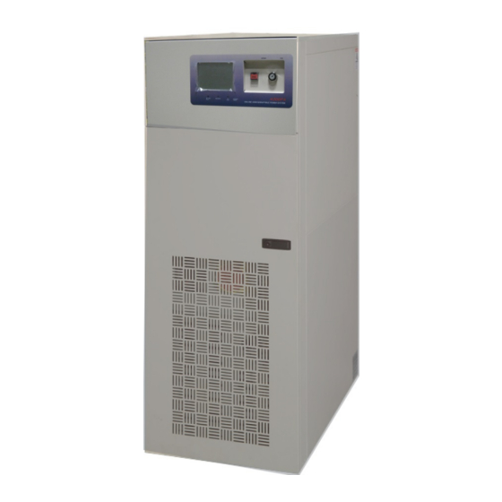
Application and Use The TOSHIBA 4200FA On-Line, Uninterruptible Power Systems (UPS) provide continuous computer grade isolated AC power in a compact, efficient, high performance unit. The UPS assures safe, reliable operation of critical office equipment, ranging from personal computers to mini-computers to local area networks (LAN). -
Page 16: Unpacking/Inspection/Storage/Disposal
Attach the rails as shown in the front to the front of the pallet. DANGER 4200FA CT/XT User’s Manual TOSHIBA remove the screws that attach the shipping crate to the pallet. Remove the crate and foam packing material. -
Page 17: Unpacking The New Ups Equipment 50 Kva
3. Place the tie brackets in the slots at the lower end of the ramps. SLOWLY roll the unit down th ramp. DANGER 4200FA CT/XT User’s Manual TOSHIBA Remove packing material. For international units, remove the screws that attach the shipping crate to the pallet. -
Page 18: Inspection Of The New Ups Equipment
It is ILLEGAL to dump lead-acid batteries in landfills or dispose of ATTENTION improperly. Please help our Earth by contacting the environmental protection agencies in your area, the battery manufacturer, or call TOSHIBA toll-free at (877) 867-8773 for more information about recycling batteries. 4200FA CT/XT User’s Manual... -
Page 19: Installation Precautions
If such interference occurs, the UPS should either be installed farther away from the affected equipment and/or powered from a different source than the affected equipment. 4200FA CT/XT User’s Manual TOSHIBA LEFT 6” (152mm) REAR 6” (152mm) RIGHT 6”... -
Page 20: System Preparation (Pre-Power)
CHARGE LED has gone out before removing the front panel of the UPS once the UPS power has been turned off. Do not attempt to disassemble, modify, or repair the UPS. Call TOSHIBA Service for repair information. Turn the power on only after attaching ALL the covers and DO NOT remove any covers of the UPS when the power is on. -
Page 21: Ups Connections
3-phase, 3-Wire *208 V requires 3-phase, 4-Wire Wye 4200FA CT/XT User’s Manual TOSHIBA When the UPS is in the Inverter mode, turning the breaker to the OFF position will cause the unit to go into the battery backup mode. The Do not EPO (Emergency Power OFF) the UPS and then reset the breaker until the UPS has been fully discharged. -
Page 22: Power Connections 15/25/30 Kva With Internal Transformer
UPS) to the terminal block of the 15/25/30 kVA UPS Models TO BATTERY SYSTEM GND Optional Bypass Input: 3-Phase, 3-Wire *208 V requires 3-Phase, 4-Wire Wye 4200FA CT/XT User’s Manual TOSHIBA CUSTOMER-PROVIDED AC DISTRIBUTION PANEL INPUT GROUND RESISTANCE LESS THAN 10 OHMS... -
Page 23: Recommended Wire Size And Torque Requirements
208 V 220 V 240 V 380 V 400 V 415 V 480 V 600 V Maximum Wire Size is 2 AWG. 4200FA CT/XT User’s Manual TOSHIBA 25 kVA Torque Torque 51 in-lbs. 51 in-lbs. 51 in-lbs. 51 in-lbs. 51 in-lbs. -
Page 24: Power Connection Cable Routing And Conduit Placement 15/25/30 Kva
1) Input and Output conductors shall be installed in separate conduits, and installed in accordance with the latest edition of NEC and the Local Authority having jurisdiction. 2) Battery conductors shall be installed in a separate conduit and be of low resistance type. 4200FA CT/XT User’s Manual TOSHIBA OUTPUT CONDUIT... -
Page 25: Control Circuit And External Battery Interface Connections 15/25/30 Kva
CIRCUITS (3-6)* BATTERY (+/-) *Indicates Class 1 wiring methods are to be used. Maximum Wire Size for Control Circuits is 12 AWG. Maximum for Battery is 2 AWG. 4200FA CT/XT User’s Manual TOSHIBA Battery Connection (+) Positive Negative 15/25/30 kVA... -
Page 26: Power Connections 50 Kva
The following illustrates the wiring connections from the power distribution panel (not part of the UPS) to the terminal block of the 50 kVA UPS Model (H1) (H2) (H3) (N) INPUT: 3-phase, 3-wire 208 V requires 3-phase, 4-wire 4200FA CT/XT User’s Manual TOSHIBA (L1) (L2) (L3) OUTPUT: 3-phase (4-wire) (H1) -
Page 27: Recommended Wire Size And Torque Requirements For Ups Input And Output Terminals
415 V 480 V 600 V Maximum Wire Size for Input is 1/0 AWG. Maximum Wire Size for Neutral is 250MCM. 4200FA CT/XT User’s Manual TOSHIBA Minimum Wire Size and Torque Requirements UPS Input and Output Terminals 50 kVA NEUTRAL... -
Page 28: Power Connection Cable Routing And Conduit Placement 50 Kva
Power Connection Cable Routing and Conduit Placement 50 kVA The following illustrates the proper cable routing that should be followed during the power connection process for the 50kVA. Removable cover for conduit access 4200FA CT/XT User’s Manual TOSHIBA Bottom Conduit Entry... -
Page 29: Control Circuit And External Interface Connections 50 Kva
UPS CONTROL CIRCUITS (1-24)* BATTERY CONTROL CIRCUITS (3-6)* *Indicates Class 1 wiring methods are to be used. Maximum Wire Size is 12 AWG. 4200FA CT/XT User’s Manual TOSHIBA (3) Battery Shunt Trip (4) Battery Shunt Trip (5) Battery Aux. (6) Battery Aux. -
Page 30: Communication Interface
1) Pin “switches” are shown in their inactive states. Example: (if battery voltage is low, pin 7 will be connected to System Common). 2) Contacts are rated at 30 VDC, 0.1 amps; 125 VAC, 3 amps. 3) Pin number “3” is not used. 4200FA CT/XT User’s Manual TOSHIBA 5 System Common DB9 Male Connector Outline... -
Page 31: Rs-232C
The RS-232C serial communication interface is available through a DB9 female connector located on the inside of the UPS. This interface allows control of the UPS from a computer network running TOSHIBA RemotEyeII™ software. The computer and the UPS serial RS-232C communication port. The available data from the UPS, via the RS-232C... -
Page 32: Specifications
24 hrs is necessary to obtain proper battery performance level before the unit is placed in operation. (***) At 6600-ft (2000 m) above sea level, output capacity should be derated by 3% (Consult Factory for higher elevations). 4200FA CT/XT User’s Manual TOSHIBA... -
Page 33: 4200Fa 15/25 Kva W/Internal Transformer
24 hrs is necessary to obtain proper battery performance level before the unit is placed in operation. (***) At 6600-ft (2000 m) above sea level, output capacity should be derated by 3% (Consult Factory for higher elevations). 4200FA CT/XT User’s Manual TOSHIBA... -
Page 34: 4200Fa 30 Kva @ 208 Vac Input/ 208 Vac Output W/Internal Batteries
24 hrs is necessary to obtain proper battery performance level before the unit is placed in operation. (***) At 6600-ft (2000 m) above sea level, output capacity should be derated by 3% (Consult Factory for higher elevations). 4200FA CT/XT User’s Manual TOSHIBA... -
Page 35: 4200Fa 30 Kva W/Internal Transformer
24 hrs is necessary to obtain proper battery performance level before the unit is placed in operation. (***) At 6600-ft (2000 m) above sea level, output capacity should be derated by 3% (Consult Factory for higher elevations). 4200FA CT/XT User’s Manual TOSHIBA Input # =(B: 208;... -
Page 36: 4200Fa 50Kva @ 208 Vac Input/ 208 Vac Output W/Internal Batteries
24 hrs is necessary to obtain proper battery performance level before the unit is placed in operation. (***) At 6600-ft (2000 m) above sea level, output capacity should be derated by 3% (Consult Factory for higher elevations). (****) Prolonged operation at this level requires some derating of the output capacity. 4200FA CT/XT User’s Manual TOSHIBA T42F3F500XAMBN... -
Page 37: 4200Fa 50Kva W/Internal Transformer
24 hrs is necessary to obtain proper battery performance level before the unit is placed in operation. (***) At 6600-ft (2000 m) above sea level, output capacity should be derated by 3% (Consult Factory for higher elevations). (****) Prolonged operation at this level requires some derating of the output capacity. 4200FA CT/XT User’s Manual TOSHIBA Input # =(B: 208;... -
Page 38: Operating The Ups
The batteries are maintained in a constantly charged state when the UPS is in the “Normal Operation Mode.” Power Flow Input Isolating Power XFMR 4200FA CT/XT User’s Manual TOSHIBA Bypass MCCB Converter Charger/ Chopper... -
Page 39: Bypass Mode
Bypass Mode for Optional Alternate Input Models Power Flow Bypass Power Input Isolating Power XFMR Power flow in Bypass mode for the Alternate Input Models 4200FA CT/XT User’s Manual TOSHIBA Bypass MCCB Converter Charger/ Chopper External Batteries Power flow in Bypass mode... -
Page 40: Battery Backup Mode
When this occurs, the batteries will stop supplying power to the load. This minimum level is the rated minimum voltage (V min). MCCB Isolating XFMR 4200FA CT/XT User’s Manual TOSHIBA Bypass Converter Inverter... -
Page 41: Battery Backup Time And Discharge Process
Battery Backup Time and Discharge Process The UPS system, when used in conjunction with a TOSHIBA designed Battery System, is designed to provide several minutes of back-up time (Refer to the Battery System Manual for back-up times). These times are valid when the unit is operating under full load. When these models are operating at half load, the batteries can provide approximately 2 times the specified value. -
Page 42: Battery Recharging
75 °F (24 °C) ambient. Model Internal Battery 324.0 VDC V float 216 VDC V min 4.0 A I charge 4200FA CT/XT User’s Manual TOSHIBA Rated Battery Voltages 15/25/30 kVA Internal Internal Transformer Battery 324 VDC 216 VDC 10.0 A... -
Page 43: Front Panel Layout (All Units)
'EMERGENCY OFF' screen. The following figure shows the UPS condition after application of the EPO switch. Use the Start-up Procedure for restarting the unit. Power Flow Input Isolating Power XFMR 4200FA CT/XT User’s Manual TOSHIBA Emergency Emergency Power Off switch power off switch (see Section 6.9) (see Section 6.6) -
Page 44: Audible Alarm Functions
BATT lamp will flicker on and off slowly (1.2 second on and 1.2 second off). The BATT LED will go off if the battery voltage reaches the shutdown level during the battery-discharge mode. On when the UPS is experiencing a fault. 4200FA CT/XT User’s Manual TOSHIBA Audible pattern .5 S .5 S... -
Page 45: Led (Light Emitting Diode) System Status
- BYPASS OPERATION - - UPS ON-LINE - - BATTERY DISCHARGE - - OUTPUT SHUTDOWN - - BATTERY BACKUP - 4200FA CT/XT User’s Manual TOSHIBA ON/OFF STATUS (After EPO received (Emergency Power Off )) LINE-1 MESSAGES Displayed when UPS is in the start-up condition or display board is resetting. -
Page 46: Line-2 System Fault Messages
* INOV * * INUV * * BATT. OH *OR MCCB-B OPEN * MM/DD/YY (DAY) HH:MM * * TRANSFER INHIBITED * * ENTER FOR DETAILS * 4200FA CT/XT User’s Manual TOSHIBA LINE-2 MESSAGES Translation DC Over-current DC Unbalanced DC Over-voltage... -
Page 47: Initial Battery Charge
2) Allow 24-72 hours for the batteries to charge and then move the Circuit Breaker to "off." 3) Repeat Initial Battery Charge procedure. (A failure indicates battery replacement may be necessary). 4200FA CT/XT User’s Manual TOSHIBA - UPS START UP - > PLEASE WAIT... -
Page 48: Start-Up Procedure
If a fault occurs during start-up, the red FAULT lamp will be "on" and the LCD screen will display a FAULT(s) DETECTED at start-up message such as the following: Refer to the "Line-2 System Fault Messages" section for details. 4200FA CT/XT User’s Manual TOSHIBA - UPS START UP - >... -
Page 49: Shutdown Procedure
Failure to adhere to the following instructions could result in damage to your WARNING equipment and/or you risk removal of power to any equipment attached to the UPS. 4200FA CT/XT User’s Manual TOSHIBA BYPASS OPERATION OUTPUT VOLTAGE=208 >CURRENT 100/100/100%... - Page 50 5) Rotate the “STOP/RUN” switch to the “RUN” position. 6) Verify that the Inverter indicator light on the front panel is lit. The unit is now back On-Line and supplying conditioned power to the load. 4200FA CT/XT User’s Manual TOSHIBA...
-
Page 51: Keypad Overview
Press to reset UPS panel’s message-display area. RESET Press to forward through display data values or to forward through menus. Press to reverse through display data values or to reverse through menus. 4200FA CT/XT User’s Manual TOSHIBA BATT BATT TEST... -
Page 52: Key Functions
The Output Line Voltages (phase-neutral, and phase to phase), Frequencies / Sync Mode, Inverter Output Power, and Power factor can be monitored by pressing the "up/down" keys. 4200FA CT/XT User’s Manual TOSHIBA - UPS ON-LINE - OUTPUT VOLTAGE= 208 V... -
Page 53: Batt Key
The following system message is displayed: Press the F1+ ENTER keys at the same time to begin the battery test and to display the following screen while batteries are tested: 4200FA CT/XT User’s Manual TOSHIBA - UPS ON-LINE - BATTERY VOLTAGE=324V CHARGE CURR.=0%... -
Page 54: Buzz Stop Key
15 seconds, a fatal time-out occurs and the following system message displays: If the 'Reset' function is successful then the display will begin from the 'Start-up screen' and then change to the 'main monitor' screen. 4200FA CT/XT User’s Manual TOSHIBA - UPS ON-LINE -... -
Page 55: Menu Data Screens
When setting this feature, press the MENU key to access the menu data screens and press the 'down' arrow key to scroll to the LCD-Idle Mode Select screen display: Press the F1 key to display the LCD-Idle mode setting adjustment screen: 4200FA CT/XT User’s Manual TOSHIBA CALENDER / CLOCK DATE (DAY) TIME >*F1: DATA SET MODE... -
Page 56: Run Switch Select
Press the MENU key to access the menu data screens and press the 'down' arrow key to scroll to the “Serial Comm Station Address” setting screen display: Press the F1 key to display the following active adjustment screen: 4200FA CT/XT User’s Manual TOSHIBA DISPLAY DURATION SET <3 MIN>... -
Page 57: Output Voltage Adjustment
Pressing the F1 key will have no effect on this display screen 6.19.7 Equalize Charge Mode Select Contact Toshiba Customer Support toll free at 1-877-867-8773 before using this option. DAMAGE to the battery system may occur if this option is used improperly. -
Page 58: Reset To Default Settings
If the STOP/RUN key switch is in the STOP position; the UPS is in the Bypass Mode and, if the overload condition is still present, the following screen will be displayed: 4200FA CT/XT User’s Manual TOSHIBA MENU DATA RESET DATA INITIALIZATION >F1: TO ACCESS RESET... -
Page 59: Backup History And Fault History
Pressing the MONI and F1 keys simultaneously, for a few seconds will cause the Battery Discharge Count screen to be displayed. Press the F1 key to display the record relating to the first discharge event. 4200FA CT/XT User’s Manual TOSHIBA - BYPASS OPERATION -... - Page 60 Press the F1 key to display the record relating to the first fault. Press the F1 key again to display the record relating to each subsequent fault. Press the ‘up’ or ‘down’ arrow keys to return to the Fault Count screen. 4200FA CT/XT User’s Manual TOSHIBA BACKUP HISTORY ( #)
-
Page 61: Ups Protection System
Operation Mode Battery Discharge after Fault Audible Alarm Battery Lamp Flickers Visible Alarm Low Battery Relay Relay Contact closed Alarm Auto-Retransfer 4200FA CT/XT User’s Manual TOSHIBA Bypass MCCB Converter Charger/ Overcurrent Chopper Low Batteryt External Batteries Built-in UPS Fault Protection Functions... -
Page 62: Start-Up/Scheduled Maintenance/Part Replacement
Maintenance Bypass. Preventive Maintenance The TOSHIBA 4200FA Uninterruptible Power Systems have been designed to provide no years of trouble-free operation requiring a minimum of preventive maintenance. The best preventive measure that the UPS user can take is to keep the area around the unit, particularly the air inlet vents, clean and free of moisture and dust accumulations. -
Page 63: Parts Replacement
C. Optionally test for the purpose of trending the battery over time. D. Re-torque all inter-battery connecting hardware (if applicable). 2) Aluminum electrolytic capacitors: Replace once every 5 years. 3) Fuses: Replace once every 7 years. 4) Cooling fan: Replace once every 3 years. 4200FA CT/XT User’s Manual TOSHIBA... -
Page 64: External Dimensions / Shipping Dimensions / Weights
9.0 External Dimensions / Shipping Dimensions / Weights External Dimensions 15/25/30 kVA 20.0 in. (508 mm) 59.7 in. (1516 mm) 56.0 in. (1422 mm) 36.3 in. (922 mm) 4200FA CT/XT User’s Manual TOSHIBA... -
Page 65: External Dimensions 50Kva
External Dimensions 50kVA 35.5 in. (901 mm) 38.3 in. (972 mm) 4200FA CT/XT User’s Manual TOSHIBA 59.3 in. (1506 mm) -
Page 66: Shipping Dimensions And Weights
50 kVA with internal battery 50 kVA with no internal transformer or battery 50 kVA with 1 internal transformer 50 kVA with 2 internal transformers 4200FA CT/XT User’s Manual TOSHIBA Shipping Dimensions, Standard Inches (cm) 42.8 (109) 49.0 (125) 64.6 (164) 67.6 (172) - Page 68 INDUSTRIAL DIVISION 13131 West Little York Rd., Houston, TX 77041 Tel: 713/466-0277 Fax 713/466-8773 US 877/867-8773 Canada 800/872-2192 Mexico 01/800/527-1204 www.toshiba.com/ind Printed in the U.S.A.