Panasonic EP-MA70 Service Manual
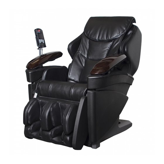
Massage lounger
Hide thumbs
Also See for EP-MA70:
- Operating instructions manual (324 pages) ,
- Manual (13 pages) ,
- Instrucciones de uso (48 pages)

Related Manuals for Panasonic EP-MA70


Summary of Contents for Panasonic EP-MA70
-
Page 1: Specifications
EP-MA70 ORDER NO. HPD1102U24CE MASSAGE LOUNGER EP-MA70 CANADA SPECIFICATIONS ©2011 Panasonic Electric Works Co., Ltd. All rights reserved. Unauthorized copying and distribution is a violation of law. - 1 -... -
Page 2: Table Of Contents
EP-MA70 ORDER NO. HPD1102U24CE Contents PAGE 1 COMPONENTS IDENTIFICATION………………………………………………………………………………………………………3 DISPLAY…………………………………………………………………………………………………………………………5 3 TURNING ON THE POWER……………………………………………………………………………………………………………6 4 REQUIRED TOOLS………………………………………………………………………………………………………………………7 5 OPERATION OF ELECTROMAGNETIC VALVES AND AIR BAGS…………………………………………………………………8 DISASSEMBLY…………………………………………………………………………………………………………………………9 7 ACTUAL WIRING…………………………………………………………………………………………………………………………41 8 CHECKING………………………………………………………………………………………………………………………………43 9 SECRET MODE…………………………………………………………………………………………………………………………59 10 EXPLODED VIEW………………………………………………………………………………………………………………………70 11 REPLACEMENT PARTS LIST…………………………………………………………………………………………………………76... -
Page 3: Components Identification
EP-MA70 ORDER NO. HPD1102U24CE 1.COMPONENTS IDENTIFICATION 1.1 MASSAGE LOUNGER - 3 -... - Page 4 EP-MA70 ORDER NO. HPD1102U24CE 1.2 CONTROLLER Control Panel *Display language on the control panel may differ depending on the region the unit was purchased. - 4 -...
-
Page 5: Display
EP-MA70 ORDER NO. HPD1102U24CE 2.Display *Display language on the control panel may differ depending on the region the unit was purchased. - 5 -... -
Page 6: Turning On The Power
EP-MA70 ORDER NO. HPD1102U24CE 3. TURNING ON THE POWER Plug the power into power socket. Turn the lock switch to the open position. Turn on the power switch on the power source switch box. ・When the operating lock switch is pointing toward ‘lock’, the power switch cannot be moved to the ‘on’ position. -
Page 7: Required Tools
EP-MA70 ORDER NO. HPD1102U24CE 4. REQUIRED TOOLS - 7 -... -
Page 8: Operation Of Electromagnetic Valves And Air Bags
EP-MA70 ORDER NO. HPD1102U24CE 5. OPERATION OF ELECTROMAGNETIC VALVES AND AIR BAGS Air massage is operated driving the Pump unit x 1pc, 3-way 3-roll electromagnetic valve, and 3-way 4-roll electromagnetic valve. When the operation stops, the Pump and all the Electromagnetic valves are OFF. -
Page 9: Disassembly
EP-MA70 ORDER NO. HPD1102U24CE 6. DISASSEMBLY 6.1. Removing the Armrests (right/left) 6.2. Removing the Outside parts - 9 -... - Page 10 EP-MA70 ORDER NO. HPD1102U24CE - 10 -...
- Page 11 EP-MA70 ORDER NO. HPD1102U24CE - 11 -...
- Page 12 EP-MA70 ORDER NO. HPD1102U24CE 6.3. Removing the Rear cover - 12 -...
- Page 13 EP-MA70 ORDER NO. HPD1102U24CE 6.4. Removing the Shoulder side air bags - 13 -...
- Page 14 EP-MA70 ORDER NO. HPD1102U24CE 6.5. Removing the Seat side unit - 14 -...
- Page 15 EP-MA70 ORDER NO. HPD1102U24CE 6.6. Removing the Seat side air unit - 15 -...
- Page 16 EP-MA70 ORDER NO. HPD1102U24CE 6.7. Removing the Seat - 16 -...
- Page 17 EP-MA70 ORDER NO. HPD1102U24CE - 17 -...
- Page 18 EP-MA70 ORDER NO. HPD1102U24CE 6.8. Removing the Under box - 18 -...
- Page 19 EP-MA70 ORDER NO. HPD1102U24CE - 19 -...
- Page 20 EP-MA70 ORDER NO. HPD1102U24CE - 20 -...
- Page 21 EP-MA70 ORDER NO. HPD1102U24CE 6.9. Removing the Ottoman - 21 -...
- Page 22 EP-MA70 ORDER NO. HPD1102U24CE - 22 -...
- Page 23 EP-MA70 ORDER NO. HPD1102U24CE - 23 -...
- Page 24 EP-MA70 ORDER NO. HPD1102U24CE - 24 -...
- Page 25 EP-MA70 ORDER NO. HPD1102U24CE - 25 -...
- Page 26 EP-MA70 ORDER NO. HPD1102U24CE - 26 -...
- Page 27 EP-MA70 ORDER NO. HPD1102U24CE 6.10. Removing the Massage mechanism block - 27 -...
- Page 28 EP-MA70 ORDER NO. HPD1102U24CE - 28 -...
- Page 29 EP-MA70 ORDER NO. HPD1102U24CE 6.11. Massage block up/down sensor gear adjustment method When the Massage mechanism block is removed from the Chair, the position of the Up/down sensor gear changes resulting in the change of the up/down stop position. When installing the Massage mechanism block on the Rear frame, be sure to adjust the position with the Up/down sensor gear.
- Page 30 EP-MA70 ORDER NO. HPD1102U24CE 6.12. Tips in installing the Connecting cord for power source Move the Massage mechanism block to the highest position. * After installing each Connecting wires, be sure to move the Massage mechanism block up and down pushing the buttons on the Controller so as to check whether each Connecting cords do not touch Belts or the Rear cover fixing plate ore at not hooked on the Up/down pinions on both sides.
- Page 31 EP-MA70 ORDER NO. HPD1102U24CE 6.13. Allocation of the Lead wires of the Massage mechanism block Allocation of the Lead wires of the Main PCB, each Motors, other parts, Cable ties are as follows: - 31 -...
- Page 32 EP-MA70 ORDER NO. HPD1102U24CE 6.14. Tips of disassembly and assembly of the Massage mechanism block 6.14.1. Removing the Up/down sensor 1. Disconnect the connector (CN106) on the Main PCB. 2. Cut the Cable tie T30R x 2, T18S x 1, which bind the Lead wires.
- Page 33 EP-MA70 ORDER NO. HPD1102U24CE 6.14.2. Removing the Intensity sensor Disconnect the Connector (CN103) on the Main PCB. Cut the Cable tie T30R x 2, T18S x 1, which bind the Lead wires. 2. Remove the Install screw on the Massage block frame and the Intensity sensor install stand.
- Page 34 EP-MA70 ORDER NO. HPD1102U24CE 6.14.3. Removing the Width sensor - 34 -...
- Page 35 EP-MA70 ORDER NO. HPD1102U24CE 6.14.4. Removing the Width motor 1. Disconnect the Connectors (CN501, CN1, CN30) on the Main PCB. 2. Cut the Cable ties (T18S, T30R) binding the Lead wires. 3. Remove the Width belt. 4. Remove two Install screws on the Width motor.
- Page 36 EP-MA70 ORDER NO. HPD1102U24CE 6.14.6. Removing the Up/down shaft (Up/down shaft bolt) * Remove the Massage mechanism block from the Massage chair before executing this work. 1. Remove the Up/down shaft bolt on the Pinion B/C with the 13mm-Box driver...
- Page 37 EP-MA70 ORDER NO. HPD1102U24CE 6.15. Removing each Lift units 6.15.1. Removing the Ottoman lift unit - 37 -...
- Page 38 EP-MA70 ORDER NO. HPD1102U24CE 6.15.2. Removing the Reclining lift unit - 38 -...
- Page 39 EP-MA70 ORDER NO. HPD1102U24CE 6.16. Removing the Rear frame - 39 -...
- Page 40 EP-MA70 ORDER NO. HPD1102U24CE 6.17. Appearance checking Check if Cable ties, Screws, Connectors, and Hoses are properly installed. - 40 -...
-
Page 41: Actual Wiring
EP-MA70 ORDER NO. HPD1102U24CE 7.ACTUAL WIRING 7.1. Air hoses - 41 -... - Page 42 EP-MA70 ORDER NO. HPD1102U24CE 7.2. Wiring (Connecting cord for power source – Sub PCB, Power source switch block) - 42 -...
-
Page 43: Checking
EP-MA70 ORDER NO. HPD1102U24CE 8. CHECKING - 43 -... - Page 44 EP-MA70 ORDER NO. HPD1102U24CE - 44 -...
- Page 45 EP-MA70 ORDER NO. HPD1102U24CE - 45 -...
- Page 46 EP-MA70 ORDER NO. HPD1102U24CE - 46 -...
- Page 47 EP-MA70 ORDER NO. HPD1102U24CE - 47 -...
- Page 48 EP-MA70 ORDER NO. HPD1102U24CE - 48 -...
- Page 49 EP-MA70 ORDER NO. HPD1102U24CE - 49 -...
- Page 50 EP-MA70 ORDER NO. HPD1102U24CE - 50 -...
- Page 51 EP-MA70 ORDER NO. HPD1102U24CE - 51 -...
- Page 52 EP-MA70 ORDER NO. HPD1102U24CE - 52 -...
- Page 53 EP-MA70 ORDER NO. HPD1102U24CE - 53 -...
- Page 54 EP-MA70 ORDER NO. HPD1102U24CE - 54 -...
- Page 55 EP-MA70 ORDER NO. HPD1102U24CE - 55 -...
- Page 56 EP-MA70 ORDER NO. HPD1102U24CE 8.2. Checking the pressure of the Air bags - 56 -...
- Page 57 EP-MA70 ORDER NO. HPD1102U24CE - 57 -...
- Page 58 EP-MA70 ORDER NO. HPD1102U24CE 8.3. Wiring diagram of Main PCB and Sub PCB The following values are in the standby conditions with the Off/On switch on the Controller pushed. Values with * are when each operations are executed. (Output voltages are approximate.) Remove Connectors to check the resistance of the parts.
-
Page 59: Secret Mode
EP-MA70 ORDER NO. HPD1102U24CE 9. SECRET MODE 9.1. Preparation of Secret Mode Before proceeding to each Secret Modes, execute the following Preparation of the Secret Mode. Insert the Power plug to the power source and turn on the Switch on the Power source switch box. - Page 60 EP-MA70 ORDER NO. HPD1102U24CE 9.2. Display of total usage time [C0] 1. Proceed the procedures 1-4 of 9.1. Preparation of Secret Mode. 2. Push the button of BACK INTENSITY till C0 appears, and push the OK button. 3. Push the OK again, then 1,000’s place, 100’s plate, ten’s place, and single’s place are shown every time you push the OK button.
- Page 61 EP-MA70 ORDER NO. HPD1102U24CE 9.4. Display of each operation time [C3] 1. Proceed the procedures of 9.1. Preparation of Secret Mode. 2. Push the button of BACK INTENSITY till C3 appears, and push the OK button twice. 3. Then, push the BACK INTENSITY and choose from 01 to 08, and from 11 to 16.
- Page 62 EP-MA70 ORDER NO. HPD1102U24CE 9.5. Display of malfunction analysis-1 [C4] . Category of abnormal stop is shown. 1. Proceed the procedures 1-4 of 9.1. Preparation of Secret Mode. 2. Push the button of BACK INTENSITY till C4 appears, and push the OK button. Any of the following is shown.
- Page 63 EP-MA70 ORDER NO. HPD1102U24CE 9.5. Display of malfunction analysis-1 [C4] . Category of abnormal stop is shown. 1. Proceed the procedures 1-4 of 9.1. Preparation of Secret Mode. 3. Push the button of BACK INTENSITY till C4 appears, and push the OK button. Any of the following is shown.
- Page 64 EP-MA70 ORDER NO. HPD1102U24CE 9.7. Display of malfunction analysis-3 [C7] It is shown which parts were stalled in the abnormal stop. 1. Proceed the procedures of 9.1. Preparation of Secret Mode. 2. Push the button of BACK INTENSITY till C7appears, and push the OK button. Any of the following is shown.
- Page 65 EP-MA70 ORDER NO. HPD1102U24CE 9.8. Display of malfunction analysis-4 [C8] * If the display is 15 (Heater error). ①: If you push OK, the Heater lights. ②: When in the condition of ①, 1) If you push the Wider switch, the Heater arm(CN101) is shown when the operation error occurred.
- Page 66 EP-MA70 ORDER NO. HPD1102U24CE 9.9. Checking after assembly [CA] Check if the Massage mechanism block is properly assembled or there is nothing wrong with the Sensors or Motors. *Detect failures in Sensors or Motors. 1. Proceed the procedures of 9.1. Preparation of Secret Mode.
- Page 67 EP-MA70 ORDER NO. HPD1102U24CE 9.11. Checking the Heater Check if the Heater increases its temperature properly by the list of the room temperature and its time till it reaches designated temperatures. (Our criterion is that the spot touching the human body is 50℃. However, there is the balance 5℃ in the Heat sensor and the spot of the human body touching the Massage ball, therefore in the list 45℃...
- Page 68 EP-MA70 ORDER NO. HPD1102U24CE 9.12. Manual mode [CE] Manual mode is used to remove or install the Massage mechanism block from or to the Massage chair, or to check each operations. 1. Proceed the procedures of 9.1. Preparation of Secret Mode.
- Page 69 EP-MA70 ORDER NO. HPD1102U24CE - 69 -...
-
Page 70: Exploded View
EP-MA70 ORDER NO. HPD1102U24CE 10. EXPLODED VIEW - 70 -... - Page 71 EP-MA70 ORDER NO. HPD1102U24CE - 71 -...
- Page 72 EP-MA70 ORDER NO. HPD1102U24CE - 72 -...
- Page 73 EP-MA70 ORDER NO. HPD1102U24CE - 73 -...
- Page 74 EP-MA70 ORDER NO. HPD1102U24CE - 74 -...
- Page 75 EP-MA70 ORDER NO. HPD1102U24CE - 75 -...
-
Page 76: Replacement Parts List
EP-MA70 ORDER NO. HPD1102U24CE 11. REPLACEMENT PARTS LIST Ref.No. Part No. Part Name & Description Remarks Unit WEPMA70L0087 REAR FRAME WEP3530L0007 SIDE HINGE FITTING RIGHT WEP3530L0017 SIDE HINGE FITTING LEFT WEP3530L6717 SCREW WEP3200L0887 RESIN BUSHING WEPMA70L0267 REAR COVER FIXING PLATE... - Page 77 EP-MA70 ORDER NO. HPD1102U24CE Ref.No. Part No. Part Name & Description Remarks Unit WEPMA70L0597 LOCK PIN SUPPORT FRAME WEPMA70L0387 LOCK PIN WEPMA70L0437 LOCK PIN RAIL WEPMA70L0607 LOCK PIN SPRING WEPMA70L0727 LOCK PIN COVER WEPMA70L0297 OTTOMAN BASE FRAME WEP3530L0927 HINGE PIN B...
- Page 78 EP-MA70 ORDER NO. HPD1102U24CE Ref.No. Part No. Part Name & Description Remarks Unit WEPMA70L0867 FOOT AIR BAG RIGHT WEPMA70L0997 FOOT AIR BAG LEFT WEP3530L9677 SCREW WEPMA70L0568 FOOT COVER WEP3200L0937 HINGE PIN MINI D WEP596N0357 SNAP PIN WEPMA70L0307 FOOT PIPE WEPMA70L0238...
- Page 79 EP-MA70 ORDER NO. HPD1102U24CE Ref.No. Part No. Part Name & Description Remarks Unit WEPMA70L3518 UNDER BOX BOTTOM WEPMA70L0707 ARMREST HOSE RIGHT WEPMA70L0717 ARMREST HOSE LEFT WEPMA70L0537 ARMREST RIGHT CONNECTING HOSE WEPMA70L0937 SEAT SIDE CONNECTING HOSE WEPMA70L0797 SEAT SIDE AIR HOSE RIGHT...
- Page 80 EP-MA70 ORDER NO. HPD1102U24CE Ref.No. Part No. Part Name & Description Remarks Unit WEPMA70L3228 SIDE COVER OUTSIDE LEFT WEPMA70K3237 SIDE COVER INSIDE RIGHT K WEPMA70C3237 SIDE COVER INSIDE RIGHT C WEPMA70K3247 SIDE COVER INSIDE LEFT K WEPMA70C3247 SIDE COVER INSIDE LEFT C...
- Page 81 EP-MA70 ORDER NO. HPD1102U24CE Ref.No. Part No. Part Name & Description Remarks Unit WEPMA70L6047 HEXAGONAL WASHER WEPMA70K3137 LEG COVER RIGHT K WEPMA70C3137 LEG COVER RIGHT C WEPMA70K3157 LEG COVER LEFT K WEPMA70C3157 LEG COVER LEFT C WEPMA70L9687 SCREW WEP3530L0167 GUIDE ROLLER SPRING...
- Page 82 EP-MA70 ORDER NO. HPD1102U24CE Ref.No. Part No. Part Name & Description Remarks Unit WEPMA50L0207 ECCENTRIC LINK PLATE RIGHT WEPMA50L0217 ECCENTRIC LINK PLATE LEFT WEP3510S9057 SCREW WEP3200L0157 ARM PULLING SPRING WEP3510L0477 INTENSITY SENSOR PLATE WEP3510L0507 INTENSITY SENSOR PLATE GREASE COVER WEP3510L0497...