Icom IC-GM1600E Service Manual
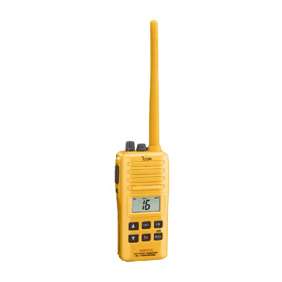
Survival craft 2-way radio
Hide thumbs
Also See for IC-GM1600E:
- Instruction manual (32 pages) ,
- Instruction manual (32 pages) ,
- Instruction manual (32 pages)
Table of Contents
Advertisement
Quick Links
Advertisement
Table of Contents

Related Manuals for Icom IC-GM1600E


Summary of Contents for Icom IC-GM1600E
- Page 1 SERVICE MANUAL SURVIVAL CRAFT 2-WAY RADIO...
- Page 2 8. READ the instructions of test equipment thoroughly before connecting equipment to the transceiver. Icom, Icom Inc. and logo are registered trademarks of Icom Incorporated (Japan) in the United States, the United Kingdom, Germany, France, Spain, Russia and/or other countries.
-
Page 3: Table Of Contents
TABLE OF CONTENTS SECTION SPECIFICATIONS SECTION INSIDE VIEWS SECTION DISASSEMBLY INSTRUCTIONS SECTION CIRCUIT DESCRIPITON RECEIVER CIRCUITS............4-1 TRANSMITER CIRCUITS . - Page 4 (at 10% distortion with an 8 Ω load) 8 Ω • Output impedance (audio) – Specifications are measured in accordance with TIA/EIA–603 and FCC PARTS 80.271 (IC-GM1600), and IEC61097 12 (IC-GM1600E). All stated specifications are subject to change without notice or obligation. 1 - 1...
- Page 5 • CHANNEL LISTS • International channels Frequency (MHz) Frequency (MHz) Frequency (MHz) Frequency (MHz) Frequency (MHz) Frequency (MHz) Transmit Receive Transmit Receive Transmit Receive Transmit Receive Transmit Receive Transmit Receive 156.050 160.650 156.550 156.550 157.050 161.650 156.075 160.675 156.575 156.575 157.075 161.675 156.100...
- Page 6 SECTION 2 INSIDE VIEWS • MAIN UNIT TOP VIEW BOTTOM VIEW Antenna Switches *D131, D151: 1SV307 D152: MA2S077 S5V Regulator (Q561: 2SA1588) Power amplifier (*Q111: RD07MVS1) T5V Regulator (Q323: 2SA1588) Pre-drive (*Q101: RD01MUS1) RF amplifier R5 Regulator IF amplifier (Q165: 3SK294) (Q322: 2SA1588) (Q211: 2SC4215) TX/RX swith...
-
Page 7: Section 3 Disassembly Instructions
SECTION 3 DISASSEMBLY INSTRUCTIONS • REMOVING THE REAR PANEL 1 Remove the speaker panel A. 2 Unscrew 2 screws B, and remove 2 washers C. 3 Unscrew 2 screws D. 4 Unscrew 2 screws E, and remove 2 washers F. 5 Remove the rear panel and the main seal from the front panel. -
Page 8: Receiver Circuits
SECTION 4 CIRCUIT DESCRIPTION The 1st IF signal from the 1st mixer is passed through the 4-1 RECEIVER CIRCUITS crystal filter (FI211) to suppress unwanted signals, and 4-1-1 ANTENNA SWITCHING CIRCUIT amplified at the 1st IF amplifier (Q211). The antenna switching circuit toggles receive line and transmit line. -
Page 9: Transmitter Circuits
4-1-6 SQUELCH CIRCUIT 4-2-2 MODULATOR CIRCUIT Squelch circuit mutes AF output signal when no signals are The modulation circuit modulates the VCO oscillating signal received. with the audio signals from the microphone. A portion of the AF signals from the FM IF IC (IC231, pin 9) are AF signals from the D/A converter (IC251, pin 3) are applied applied to the IC251 to control the level, and the active filter to the modulation circuit (D39) to modulate the oscillated... -
Page 10: Pll Circuits
The phase detector compares the input signal with a 4-3 PLL CIRCUITS reference frequency, and then outputs the control signal 4-3-1 GENERAL (pulse-type) from pin 5. The pulse-type signal is converted PLL circuits control TX and RX VCO circuits. IC1 is a into DC voltage at the loop filter (R17–R19, C16, C17), and PLL IC and contains prescaler, programmable counter, then applied to the RX VCO (Q41, D31–D34) as the lock... -
Page 11: Power Supply Circuits
4-4 POWER SUPPLY CIRCUITS PORT DESCRIPTION NUMBER NAME 4-4-1 VOLTAGE LINES Output port for dimmer control LINE DESCRIPTION 77, 78 LEDS1, LEDS2 signal. The voltage from the connected DC power Output port for microphone mute supply passed through the [VOL] switch (R1: MICMS signal. -
Page 12: Section 5 Adjustment Procedures
SECTION 5 ADJUSTMENT PROCEDURES 5-1 PREPARATION REQUIRED TEST EQUIPMENTS When adjusting IC-GM1600/E, the optional CS-M90/GM1600 ADJ (Rev. 1.0 or later), OPC-478 (RS-232 ADJUSTMENT SOFTWARE type) or OPC-478U (USB type) OPC-1028 and JIG cable (see page 5-2) are required. CLONING CABLE, EQUIPMENT GRADE AND RANGE EQUIPMENT... - Page 13 • CONNECTION AC millivoltmeter Audio generator OPC-478 (RS-232C type) to RS-232C port Standard signal generator to the antenna connector 0.1 µV to 32 mV (–127 dBm to –17 dBm) OPC-478U (USB type) DO NOT transmit while to USB port an SSG is connected to the antenna connector.
- Page 14 • PC SCREEN EXAMPLE I/O check button NOTE: The above screen is an example. Each transceiver has its own specific values for each setting. q: Adjustment condition y: Receive sensitivity (Manualy) w: Reference frequency u: Squelch level e: RF output power i: S-meter r: FM deviation (Wide) o: VOX...
-
Page 15: Software Adjustments
5-2 SOFTWARE ADJUSTMENT (FREQUENCY) Select the adjustment item with [↑] / [↓] keys, then set the value with [←] / [→] keys on the connected PC. MEASUREMENT ADJUSTMENT ADJUSTMENT CONDITION VALUE UNIT OPERATION PLL LOCK 1 • Operating CH. : 16 Check the LVIN Data cell's 1.5–3.0 V [USA] VOLTAGE... - Page 16 5-2 SOFTWARE ADJUSTMENT (TRANSMITTING) Select the adjustment item with [↑] / [↓] keys, then set the value with [←] / [→] keys on the connected PC. MEASUREMENT ADJUSTMENT ADJUSTMENT CONDITION VALUE UNIT OPERATION OUTPUT POWER 1 • Operating CH. : 16 Connect the RF power meter to [RF Power (High)] •...
- Page 17 5-2 SOFTWARE ADJUSTMENT (RECEIVING) Select the adjustment item with [↑] / [↓] keys, then set the value with [←] / [→] keys on the connected PC. MEASUREMENT ADJUSTMENT ADJUSTMENT CONDITION VALUE UNIT OPERATION Connect the distortion meter with an 8 Ω RECEIVE 1 •...
-
Page 18: Section 6 Parts List
SECTION 6 PARTS LIST • IC-GM1600/E [MAIN UNIT] [MAIN UNIT] ORDER ORDER DESCRIPTION DESCRIPTION LOCATION LOCATION 1140005990 S.IC MB15A02PFV1-G-BND-ER 55.7/12.1 1790000620 S.DIO MA77 (TX) 81.3/22 IC141 1110002750 S.IC TA75S01F (TE85R) T 107.2/24.2 D121 1790001670 S.DIO RB706F-40T106 T 108.3/15.9 IC231 1110003201 S.IC TA31136FNG (EL) 76.4/36.5... - Page 19 [MAIN UNIT] [MAIN UNIT] ORDER ORDER DESCRIPTION DESCRIPTION LOCATION LOCATION S.RES ERJ2GEJ 120 X (12 Ω) 7030005050 S.RES ERJ2GEJ 103 X (10 kΩ) 49.7/7.2 R204 7030010430 85.9/20.8 S.RES ERJ2GEJ 471 X (470 Ω) 7030005210 S.RES ERJ2GEJ 822 X (8.2 kΩ) 45.8/4.5 R205 7030005000...
- Page 20 [MAIN UNIT] [MAIN UNIT] ORDER ORDER DESCRIPTION DESCRIPTION LOCATION LOCATION R431 7030005600 S.RES ERJ2GEJ 273 X (27 kΩ) T 106.1/27.6 R682 7030005700 S.RES ERJ2GEJ 274 X (270 kΩ) 6.6/26.5 R683 7030006610 S.RES ERJ2GEJ 394 X (390 kΩ) 12/29.3 R432 7030005160 S.RES ERJ2GEJ 105 X (1 MΩ) T 107.6/27.1 R433...
- Page 21 [MAIN UNIT] [MAIN UNIT] ORDER ORDER DESCRIPTION DESCRIPTION LOCATION LOCATION 4030007000 S.CER C1608 CH 1H 090D-T 78.9/21.2 C231 4030017460 S.CER ECJ0EB1E102K 82.8/38.2 C232 4030007130 S.CER C1608 CH 1H 101J-T 75.7/34.7 4030017460 S.CER ECJ0EB1E102K 83/16.2 4030017460 S.CER ECJ0EB1E102K 86.1/14.2 C233 4030016930 S.CER ECJ0EB1A104K 73.3/35 4030017420...
- Page 22 [VR UNIT] [MAIN UNIT] ORDER ORDER DESCRIPTION DESCRIPTION LOCATION LOCATION R801 7210002530 TP96N937N-15F-10KA-1540 C522 4030016970 S.CER ECJ0EB1C223K 48.2/30 C531 4030016950 S.CER ECJ0EB1A473K 35.2/15.5 C532 4030016940 S.CER ECJ0EB1A393K 37.8/18.6 5210000900 S.FUS 0434003.NRP 12.2/4.4 C533 4030016930 S.CER ECJ0EB1A104K 37.3/20.9 C534 4030017740 S.CER ECJ0EB1E821K 39.4/23.7 C535 4030016790...
- Page 23 SECTION 7 MECHANICAL PARTS AND DISASSEMBLY 7-1 CABINET PARTS [MAIN UNIT] [MIC BOARD] REF. ORDER. NO. DESCRIPTION QTY. REF. ORDER. NO. DESCRIPTION QTY. DS681 5030002790 LCD A0286 J416 6510024650 246S-550-4P-134 connector EP681 8930064210 LCD contact SRCN-2795-SP-N-W [ACCESSORIES] MP681 8930063850 2795 LCD holder REF.
- Page 24 EP1 ( A ) Grease NOTE 2 MP73 MP71 ( C ) MP66 ( C ) MP80 ( C ) MP46 ( C ) NOTE 2 J41 ( C ) MP71 ( C ) MP75 ( C ) MP73 Unit: mm (inch) MP69 ( C ) MP74 ( C ) MP74 ( C )
-
Page 25: Section 8 Semiconductor Information
SECTION 8 SEMICONDUCTOR INFORMATION • BC-158 CHARGER PARTS LIST • TRANSISTORS AND FET’s 2SA1588 GR 2SB1132 Q 2SC4116 BL 2SC4116 GR 2SC4213 B (Symbol: ZG) (Symbol: BAQ) (Symbol: LL) (Symbol: LG) (Symbol: AB) MECHANICAL PARTS MP1(C) [CHASSIS UNIT] REF. ORDER. NO. DESCRIPTION QTY. -
Page 26: Section 9 Board Layouts
SECTION 9 BOARD LAYOUTS 9-1 MAIN UNIT • TOP VIEW Horizontal MC461 J412 (CHASSIS unit) R277 to the SP1 IC282 Q442 R611 D231 R441 S100 S101 C441 AFOUT R236 R234 – C217 SPGO R237 Q211 R243 C552 R216 J414 R235 C245 R232 R214... - Page 27 • BOTTOM VIEW S641 R461 C461 B6190B J352 S461 C266 R274 C473 C691 FI231 C268 C463 C270 R270 R718 VOLO R463 C462 C467 C395 R709 C696 VOLIN R387 C391 R467 R697 R696 C689 C465 C381 R700 R701 Q551 R264 C481 C397 C695 R262...
-
Page 28: Vr Board
9-2 VR BOARD • TOP VIEW Horizontal 9-3 MIC BOARD • TOP VIEW Horizontal J416 9-4 BC-158 • TOP VIEW Horizonal B5787B to the AC adapter AC-147A/E 9 - 3... - Page 29 • BOTTOM VIEW Horizontal • BOTTOM VIEW Horizontal J415 to the MAIN unit J414 J415 EP458 EP451 B6192B R714 DS655 R713 • BOTTOM VIEW Horizonal 9 - 4...
-
Page 30: Block Diagram
SECTION 10 BLOCK DIAGRAM ANTENNA RIPPLE 146-174 MHz Q47: XP6501 Q91: Q101: Q111: D91, D92: MA77 2SC5110 RD01MUS1 RD07MVS1 Q61: 2SC4215 Q62: 2SC4215 Q41: 2SC4226 LOINV D31-34: HVC350B TX/RX BUFF BUFF BUFF BUFF DRIVE Q3: 2SK880 VCOS D39: IC141: D132: 1SV245 TA75S01F 1SS375... -
Page 31: Voltage Diagram
SECTION 11 VOLTAGE DIAGRAM 11-1 MAIN UNIT SRXMS CTFIS DETMS MODIN DS653 SML-311YT EP682 CV1083 Q651 XP1213 IC261 NJM12902V IC261 NJM12902V R262 R272 R274 C270 12 k 150 k 0.01 C262 C261 0.015 0.033 R270 15 k AF7V R411 C411 IC261 R275 C269... - Page 32 NOTES : Contorol line SRXMS Common line TX line CTFIS DETMS RX line MODIN Q655 UMD6 L124 EP111 2.7 H MPZ1608S221A R19 470 V5FV V5FV R122 EP101 BLM11B221SB 2SC4226 R25 PLL5V XP6501 AB C106 L102 0.001 18 nH 150 k L112 R47 2.2 k ELJNC R47K 0.47U...
- Page 33 : http://www.icomspain.com Highway 17 Delta, B.C., V4K 5B8, Canada Phone : +1 (604) 952-4266 Fax : +1 (604) 952-0090 E-mail : icom@icomspain.com : http://www.icomcanada.com E-mail : info@icomcanada.com Unit 9, Sea St., Herne Bay, Kent, CT6 8LD, U.K. Phone : +44 (01227) 741741 Fax : +44 (01227) 741742 : http://www.icomuk.co.uk...
- Page 34 S-141221Z-C1-q © 2005 Icom Inc.