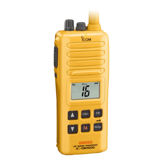
Icom IC-GM1600 Instruction Manual
Survival craft 2-way radio
Hide thumbs
Also See for IC-GM1600:
- Instruction manual (32 pages) ,
- Service manual (34 pages) ,
- Instruction manual (32 pages)

Related Manuals for Icom IC-GM1600


Summary of Contents for Icom IC-GM1600
- Page 1 INSTRUCTION MANUAL SURVIVAL CRAFT 2-WAY RADIO iGM1600 This device complies with Part 15 of the FCC Rules. Operation is subject to the condition that this device does not cause harmful inter- ference.
- Page 2 • ALWAYS keep the antenna at least 2.5 cm (1 inch) away from the body when transmitting and only use the Icom belt-clips which are listed on page 26 when attaching the radio to your belt, etc., to ensure FCC RF ex- posure compliance requirements are not exceeded.To provide the recipi-...
-
Page 3: Recommendation
Water may enter into the transceiver, and damage it. FOREWORD Thank you for purchasing this Icom radio. The IC-GM1600 SUR- VIVAL CRAFT 2-WAY RADIO is designed and built with Icom’s state of the art technology and craftsmanship. With proper care, this product should provide you with years of trouble-free oper- ation. -
Page 4: Precaution
For U.S.A. only CAUTION: Changes or modifications to this device, not expressly approved by Icom Inc., could void your authority to operate this device under FCC regulations. Icom, Icom Inc. and the logo are registered trademarks of Icom Incor- porated (Japan) in the United States, the United Kingdom, Germany, France, Spain, Russia and/or other countries. -
Page 5: Table Of Contents
TABLE OF CONTENTS SAFETY TRAINING INFORMATION ... i RECOMMENDATION ... ii FOREWORD ... ii IMPORTANT ... ii EXPLICIT DEFINITIONS ... ii PRECAUTION ... iii TABLE OF CONTENTS ... iv 1 OPERATING RULES ... 1 2 SUPPLIED ACCESSORIES AND ATTACHMENTS ... 2–3 I Supplied accessories ... -
Page 6: Operating Rules
OPERATING RULES D Priorities • Read all rules and regulations pertaining to priorities and keep an up-to-date copy handy. Safety and distress calls take priority over all others. • You must monitor Channel 16 when you are not operating on another channel. •... -
Page 7: Supplied Accessories And Attachments
SUPPLIED ACCESSORIES AND ATTACHMENTS I Supplied accessories The following accessories are supplied: q Handstrap ........1 w Battery charger (BC-158) . -
Page 8: Battery Pack
Turn the screw counterclockwise, then pull the battery pack in the direction of the arrow as shown below. To attach the battery pack: Insert the battery pack in the IC-GM1600 completely, then turn the screw clockwise. NEVER remove or insert the battery pack when the trans- ceiver is wet or soiled. -
Page 9: Panel Description
I Front, top and side panels PANEL DESCRIPTION q VOLUME CONTROL [VOL] Turns power ON and adjusts the audio level. w MICROPHONE CONNECTOR [MIC/SP] Connects the optional external microphone. NOTE: Attach the [MIC/SP] cap when the optional speaker-microphone is not used. e ANTENNA Fixed type. -
Page 10: I Function Display
PANEL DESCRIPTION i CHANNEL 16 KEY [16] Selects Channel 16 when pushed. (p. 7) o CHANNEL UP/DOWN KEYS [Y Y ]/[Z Z ] ➥ Selects an operating channel. (pgs. 7–8) ➥ Selects the SET mode condition of the item. (p. 11) ➥... - Page 11 t BATTERY INDICATOR Indicates remaining battery power. y VOX INDICATOR “VOX” appears when the VOX function is used. (p. 10) u SET MODE ITEM READOUT Indicates the SET mode items while in the SET mode. (p. 11) i LOCK INDICATOR Appears when the lock function is activated.
-
Page 12: Basic Operation
BASIC OPERATION I Channel selection D Channel 16 Channel 16 (Distress channel) is used for establishing initial contact with another station and for emergency communica- tions. While standing by, you must monitor Channel 16. q Push [16] to select Channel 16. w Push [CH] to return to the condition before selecting Chan- nel 16, or push [Y]/[Z] to select the operating channel. -
Page 13: I Receiving And Transmitting
The power save function activates automatically when no signal is received for 5 sec. For U.S.A version: To prevent accidental prolonged trans- mission, etc., the IC-GM1600 has a time-out-timer func- tion. The timer cuts a transmission OFF after 5 min. of con- tinuous transmission. -
Page 14: I Call Channel Programming
• The call channel number stops flashing. I Adjusting the squelch level To adjust the IC-GM1600’s squelch level, use the [Y]/[Z] keys. In order to receive signals properly, the squelch must be ad- justed to the proper level. -
Page 15: I Lock Function
I Lock function This function electronically locks all keys (except for [PTT], [SQL• ] and [Hi/Lo• ]) to prevent accidental channel MONI changes and function access. ➥ Push [Hi/Lo• ] for 1 sec. to turn the lock function ON and OFF. Push for 1 sec. -
Page 16: Set Mode
SET MODE I SET mode programming SET mode is used to change the condition of 11 transceiver functions: beep tone function, monitor switch action, back- lighting function, LCD contrast selection, auto power save function, self check function, battery voltage indicator, signal strength indicator, squelch sensitivity function, VOX gain* and VOX delay*. -
Page 17: I Set Mode Items
I SET mode items D Beep tone function “bP” You can select silent operation by turning the beep tones OFF, or you can have 2 types of confirmation beeps sound at the push of a key. When “ON” is selected, a fixed beep (Pi) sounds, and when “US”... - Page 18 SET MODE D Auto power save function “PS” The auto power save function reduces battery drain by deac- tivating the receiver circuit for preset intervals. • ON : The power save function is turned ON. The power save func- tion will activate when no signal is received, and no operation is performed for 5 sec.
- Page 19 D Battery voltage indicator “bt” This function controls display or non-display settings of the connected battery pack’s voltage when the power is ON. • The voltage of the connected battery pack is displayed for 2 sec. after power is turned ON. Push Battery voltage Battery voltage...
- Page 20 SET MODE D VOX delay “dL” (Available for on-board use only) Sets the VOX delay timer (0.5 to 3.0 sec. in 0.5 sec. steps) keeping the radio in transmit mode after you stop speaking. • Setting the delay to 0.5 (0.5 sec.) is a short VOX delay. •...
-
Page 21: Bp-234 Battery Pack
The optional BP-234 battery pack is a non-rechargeable, Lithium battery pack for operation in a survival craft. The fol- lowing precaution must be observed. NEVER • dispose of the BP-234 battery pack in a fire. This could re- sult in an explosion. DO NOT •... -
Page 22: Battery Charging (For On-Board Use Only)
BATTERY CHARGING (FOR ON-BOARD USE ONLY) I Battery charging Prior to using the transceiver for the first time, the battery pack must be fully charged for optimum life and operation. CAUTION: To avoid damage to the transceiver, turn the power OFF while charging. •... - Page 23 DO NOT charge the BP-224 more than 12 hours. Oth- erwise, the BP-224 will be damaged. Turn power OFF BP-224 Charge indicator Lights green when the BP-224 (with/without IC-GM1600) is inserted. AC adapter* *Plug type is dependent on version. BATTERY CHARGING (FOR ON-BOARD USE ONLY) IC-GM1600 Supplied screws...
-
Page 24: I Optional Battery Chargers
BATTERY CHARGING (FOR ON-BOARD USE ONLY) I Optional battery chargers ï AD-109 installation q Connect the charger’s 10-pin connector to the AD-109 desktop charger adapter’s plug. NOTE: The 3-pin connector is not used. Desktop charger adapter Plug w Install the adapter into the charger in the direction of the arrow, then use the supplied 2 screws to attach the charger adapter to the charger. - Page 25 The following are additionally required. • AD-109 charger adapter • An AC adapter (BC-145A/E)* or the DC power cable (OPC-515L/CP-17L). Depends on version. IC-GM1600 Turn power OFF BP-224 AC adapter* Plug type is dependent on version. Optional OPC-515L (for 13.8 V power...
-
Page 26: Optional Swivel Belt Clip
OPTIONAL SWIVEL BELT CLIP I MB-86 contents Belt clip ………………………………………………………… 1 Base clip ……………………………………………………… 1 Supplied screws ……………………………………………… 2 I Attachment q Screw the base clip to the back of the transceiver using the two screws (supplied) as shown below. Supplied screws w Clip the belt clip over your belt and insert the transceiver. -
Page 27: Optional Speaker-Microphone (For On-Board Use Only)
OPTIONAL SPEAKER-MICROPHONE (FOR ON-BOARD USE ONLY) I HM-125 descriptions Alligator-type clip To attach the speaker-mic. to your shirt or collar, etc. PTT switch Transmits when push. Receives when release. Microphone Speaker NEVER immerse the connector in water without connecting with the transceiver. If the connector becomes wet, be sure to dry BEFORE connecting it to the transceiver. -
Page 28: Channel List For Survival Operation
CHANNEL LIST FOR SURVIVAL OPERATION Channel number TX/RX 156.300 MHz 156.500 MHz 156.650 MHz 156.800 MHz 156.425 MHz 156.625 MHz 156.875 MHz *U.S.A. version is low power only Channel number TX/RX 156.400 MHz 156.550 MHz 156.700 MHz 156.850 MHz 156.475 MHz 156.675 MHz Channel number TX/RX... -
Page 29: Troubleshooting
PROBLEM POSSIBLE CAUSE The transceiver does • The battery is exhausted. not turn ON. • Bad connection to the battery pack. No sound from the • Squelch level is too deep. speaker. • Volume level is too low. • Speaker has been exposed to water. •... -
Page 30: Specifications
SPECIFICATIONS D GENERAL • Frequency coverage TX/RX : 156.300–156.875 MHz • Mode : 16K0G3E • Channel spacing : 25 kHz • Power supply requirement : Battery packs (BP-234 or BP- • Current drain (approx.) : TX High (2 W) 1.0 A at 7.5 V DC for [USA] at 7.2 V DC for [GEN] •... -
Page 31: Options
D BATTERY PACKS <FOR SURVIVAL CRAFT USE> • BP-234 LITHIUM BATTERY PACK 9.0 V/3300 mAh Lithium battery pack. <FOR ON-BOARD USE> • BP-224 Ni-Cd BATTERY PACK 7.2 V/750 mAh Ni-Cd battery pack. • BP-225 Ni-Cd BATTERY PACK 7.2 V/1100 mAh Ni-Cd battery pack. D BELT CLIPS •... - Page 32 A-6383D-1EX Printed in Japan 1-1-32 Kamiminami, Hirano-ku, Osaka 547-0003, Japan 2004 Icom Inc. ©...