Table of Contents
Advertisement
Advertisement
Table of Contents

Related Manuals for HP EliteDesk 705 G5


Summary of Contents for HP EliteDesk 705 G5
- Page 1 Maintenance and Service Guide HP EliteDesk 705 G5 Desktop Mini...
- Page 2 Bluetooth is a trademark owned by its bound by the terms of the HP End User License Not all features are available in all editions or proprietor and used by HP Inc. under license.
- Page 3 Safety warning notice WARNING! To reduce the possibility of heat-related injuries or of overheating the computer, do not place the computer directly on your lap or obstruct the computer air vents. Use the computer only on a hard, flat surface. Do not allow another hard surface, such as an adjoining optional printer, or a soft surface, such as pillows or rugs or clothing, to block airflow.
- Page 4 Safety warning notice...
-
Page 5: About This Guide
About this guide WARNING! Indicates a hazardous situation that, if not avoided, could result in serious injury or death. CAUTION: Indicates a hazardous situation that, if not avoided, could result in minor or moderate injury. IMPORTANT: Indicates information considered important but not hazard-related (for example, messages related to property damage). - Page 6 About this guide...
-
Page 7: Table Of Contents
Table of contents 1 Computer features ............................1 Front panel components ............................2 Rear panel components ............................3 Serial number location ............................4 Changing from desktop to tower orientation ......................5 Attaching the computer to a mounting fixture ..................... 6 Installing a security lock ............................ - Page 8 SATA data cable ....................... 19 Cable management ........................... 20 4 Removal and replacement procedures ......................21 Warnings and cautions ............................21 Preparation for disassembly ..........................22 Front bezel dust filter ............................22 Access panel ................................. 23 Front bezel ................................24 Hood sensor .................................
- Page 9 Using HP PC Hardware Diagnostics UEFI ......................103 Starting HP PC Hardware Diagnostics UEFI ..................104 Downloading HP PC Hardware Diagnostics UEFI to a USB flash drive ..........104 Downloading the latest HP PC Hardware Diagnostics UEFI version ......104...
- Page 10 Backing up information and creating recovery media ..................107 Using Windows tools ........................107 Using the HP Cloud Recovery Download Tool to create recovery media (select products only) ... 107 Restoring and recovery ............................. 108 Restoring, resetting, and refreshing using Windows tools ............108 Recovering using HP Recovery media .....................
-
Page 11: Computer Features
Computer features Features vary depending on the model. For support assistance and to learn more about the hardware and software installed on your computer model, run the HP Support Assistant utility. NOTE: You can use this computer model in a tower orientation or a desktop orientation. -
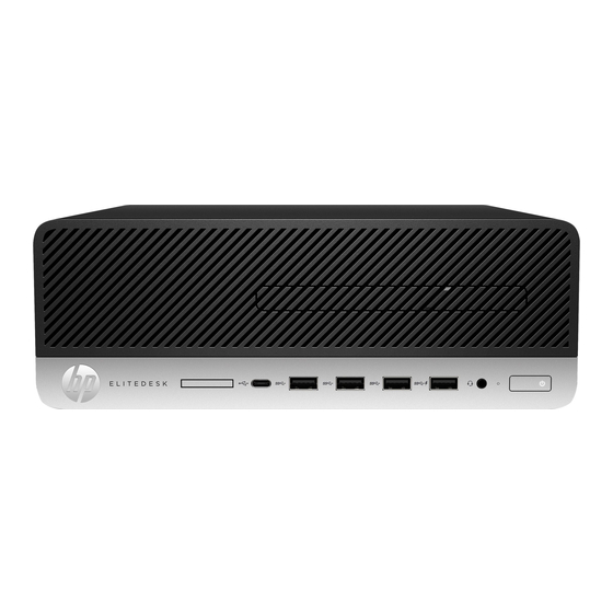
Page 12: Front Panel Components
Audio-out (headphone)/Audio-in (microphone) combo jack USB SuperSpeed port Hard drive activity light USB SuperSpeed port with HP Sleep and Charge Power button Audio-out (headphone) jack NOTE: The combo jack supports headphones, line output devices, microphones, line input devices, or CTIA style headsets. -
Page 13: Rear Panel Components
Rear panel components Table 1-2 Identifying the rear panel components Rear panel components Security cable slot USB SuperSpeed ports* (2) DisplayPort™ monitor connectors (2) RJ-45 (network) jack USB SuperSpeed ports (2) Power cord connector Optional port* *Optional port offers choice of HDMI 2.0a, DisplayPort 1.2, VGA, serial port or USB Type-C. **Bottom port allows for wake from keyboard. -
Page 14: Serial Number Location
Serial number location Each computer has a unique serial number and a product ID number that are located on the exterior of the computer. Keep these numbers available when contacting customer service for assistance. Chapter 1 Computer features... -
Page 15: Changing From Desktop To Tower Orientation
Changing from desktop to tower orientation The computer can be used in a tower orientation with an optional tower stand that can be purchased from HP. Remove or disengage any security devices that prohibit opening the computer. Remove all removable media, such as a USB flash drive, from the computer. -
Page 16: Attaching The Computer To A Mounting Fixture
Attaching the computer to a mounting fixture The computer can be attached to a wall, swing arm, or other mounting fixture. NOTE: This apparatus is intended to be supported by UL or CSA Listed wall mount bracket. If the computer is on a stand, remove the computer from the stand and lay the computer down. To attach the computer to a swing arm (sold separately), insert four screws through the holes on the swing arm plate and into the mounting holes on the computer. -
Page 17: Installing A Security Lock
Installing a security lock You can attach a security cable lock to the rear of the computer. Use the key provided to attach and remove the lock. To install a padlock, slide the padlock loop out from the rear of the computer and install the padlock in the loop. -
Page 18: Illustrated Parts Catalog
Illustrated parts catalog NOTE: HP continually improves and changes product parts. For complete and current information on supported parts for your computer, go to http://partsurfer.hp.com, select your country or region, and then follow the on-screen instructions. Computer major components Item... - Page 19 Item Description 1 TB, 7200 rpm, 7 mm 500 GB, 7200 rpm, 7 mm 500 GB, 7200 rpm, OPAL2, self-encrypting drive (SED), 7 mm 500 GB, 5400 rpm, FIPS, 7 mm Solid-state drives, 2.5 inch, SATA-3, TLC 512 GB, FIPS-140-2 512 GB, OPAL 2, self-encrypting drive (SED) 512 GB 256 GB, FIPS-140-2...
-
Page 20: Mass Storage Devices
Item Description (15) Computer chassis Processor (include replacement thermal material) AMD Ryzen™ 5 3400 AMD Ryzen 5 3400GE AMD Ryzen 3 3200 AMD Ryzen 3 3200GE AMD Athlon 300GE Option board HDMI option board DisplayPort option board VGA option board Serial port option board USB Type-C option board USB Type-C option board with 100 W power delivery option board... -
Page 21: Miscellaneous Parts
Hard drive cage Miscellaneous parts Description AC adapter 150 W, APFC 90 W, APFC 65 W, nPFC Front bezel dust filter (not illustrated) Antenna cable, wireless Stand EPS bracket Quick release 2 HP USB-Type C to USB Type-A Hub Miscellaneous parts... - Page 22 Description Adapters USB Type-C to DisplayPort USB Type-C to USB 3.0 Keyboard Washable, PVC, USB/PS2 Conferencing, USB USB, slim Wireless keyboard and mouse Smart card, slim, CCID, USB Anti-microbial, slim Grey, slim, USB Collaboration, USB Collaboration, wireless Wireless, premium Health care, wired, USB Premium, wireless, keyboard and mouse Mouse USB, optical...
-
Page 23: Routine Care, Sata Drive Guidelines, And Disassembly Preparation
Routine care, SATA drive guidelines, and disassembly preparation This chapter provides general service information for the computer. Adherence to the procedures and precautions described in this chapter is essential for proper service. IMPORTANT: When the computer is plugged into an AC power source, voltage is always applied to the system board. -
Page 24: Preventing Electrostatic Damage To Equipment
Table 3-1 Static electricity occurrence based on activity and humidity (continued) Relative humidity Removing DIPs from vinyl tray 2,000 V 4,000 V 11,500 V Removing DIPs from polystyrene foam 3,500 V 5,000 V 14,500 V Removing bubble pack from PCB (printed circuit board) 7,000 V 20,000 V 26,500 V... -
Page 25: Grounding The Work Area
● Use field service tools, such as cutters, screwdrivers, and vacuums that are conductive. Recommended materials and equipment HP recommends the following materials and equipment to prevent static electricity: Antistatic tape ● Antistatic smocks, aprons, or sleeve protectors ●... -
Page 26: Operating Guidelines
Operating guidelines To prevent overheating and to help prolong the life of the computer: Keep the computer away from excessive moisture, direct sunlight, and extremes of heat and cold. ● Operate the computer on a sturdy, level surface. Leave a 10.2 cm (4 inch) clearance on all vented sides of ●... -
Page 27: Cleaning The Keyboard
After cleaning, always wipe the unit with a clean, lint-free cloth. ● ● Occasionally clean the air vents on the computer. Lint and other foreign matter can block the vents and limit the airflow. Cleaning the keyboard Follow all safety precautions in General cleaning safety precautions on page 16 before cleaning the keyboard. -
Page 28: Tools And Software Requirements
If an incorrect screw is used during the reassembly process, it can damage the unit. HP strongly recommends that all screws removed during disassembly be kept with the part that was removed and then returned to their proper locations. -
Page 29: Lithium Coin Cell Battery
Do not dispose of batteries, battery packs, and accumulators with general household waste. In order to forward them to recycling or proper disposal, please use the public collection system or return them to HP, their authorized partners, or their agents. -
Page 30: Cable Management
Cable management Always follow good cable management practices when working inside the computer. Keep cables away from major heat sources like the heat sink. ● Keep cables clear of sliding or moveable parts to prevent them from being cut or crimped when the parts ●... -
Page 31: Removal And Replacement Procedures
Not all features listed in this guide are available on all computers. NOTE: HP continually improves and changes product parts. For complete and current information on supported parts for your computer, go to http://partsurfer.hp.com, select your country or region, and then follow the on-screen instructions. Warnings and cautions Before performing upgrades be sure to carefully read all of the applicable instructions, cautions, and warnings in this guide. -
Page 32: Preparation For Disassembly
Preparation for disassembly Routine care, SATA drive guidelines, and disassembly preparation on page 13 for initial safety procedures. Remove or disengage any security devices that prohibit opening the computer. Remove all removable media, such as a USB flash drive, from the computer. Turn off the computer properly through the operating system, and then turn off any external devices. -
Page 33: Access Panel
Access panel To access internal components, you must remove the access panel: Prepare the computer for disassembly (Preparation for disassembly on page 22). Remove the thumbscrew on the rear of the computer (1), and then slide the panel forward and lift it off the computer (2). -
Page 34: Front Bezel
Front bezel NOTE: It is not necessary to remove the front bezel to access other components. The front bezel is secured to the top cover by tabs. Prepare the computer for disassembly (Preparation for disassembly on page 22). Remove the access panel (Access panel on page 23). -
Page 35: Hood Sensor
Hood sensor The hood sensor is located near the front of the computer. Prepare the computer for disassembly (Preparation for disassembly on page 22). Remove the access panel (Access panel on page 23). Lift the rubber cover from the hood sensor (1). Disconnect the cable from the system board, and then lift the hood sensor out of the computer (2). -
Page 36: Speaker
Speaker A single speaker is located on the left side of the computer behind the front bezel, inside the chassis. It is secured by a white peg that you pull out to release. To remove the speaker: Prepare the computer for disassembly (Preparation for disassembly on page 22). -
Page 37: Hard Drive
Hard drive Models with a hard drive and drive cage do not include a separate graphics processor card. For a list of available hard drives, see Mass storage devices on page NOTE: Before you remove the old hard drive, be sure to back up the data from the old hard drive so that you can transfer the data to the new hard drive. -
Page 38: Hard Drive Connector
Hard drive connector The hard drive connector is installed in the hard drive cage and connects to the system board. Prepare the computer for disassembly (Preparation for disassembly on page 22). Remove the access panel (Access panel on page 23). Remove the hard drive (Hard drive on page 27). -
Page 39: Drive Cage
Drive cage Prepare the computer for disassembly (Preparation for disassembly on page 22). Remove the access panel (Access panel on page 23). Remove the hard drive (Hard drive on page 27). Lift the connector latch on the system board (1), and then disconnect the hard drive cable using the pull tab on the cable (2). -
Page 40: Graphics Processor And Heat Sink Assembly
Graphics processor and heat sink assembly IMPORTANT: Do not remove the heat sink/fan from the graphics processor. Remove the assembly as an entire unit. For a list of available graphics processors, see Computer major components on page Prepare the computer for disassembly (Preparation for disassembly on page 22). -
Page 41: Pcie Solid State Drive (Ssd)
M.2 PCIe solid state drive (SSD) For a list of available solid-state drives, see Mass storage devices on page Prepare the computer for disassembly (Preparation for disassembly on page 22). Remove the access panel (Access panel on page 23). In models with a hard drive, remove the hard drive (Hard drive on page 27) and drive cage Drive cage... - Page 42 Remove the screw (1) securing the solid-state drive to the system board, and then pull the drive from the socket on the system board (2). To replace the solid-state drive module, reverse the removal procedures. Chapter 4 Removal and replacement procedures...
-
Page 43: Wlan Module
WLAN module For a list of available WLAN modules, see Computer major components on page Prepare the computer for disassembly (Preparation for disassembly on page 22). Remove the access panel (Access panel on page 23). In models with a hard drive, remove the hard drive (Hard drive on page 27) and drive cage Drive cage... - Page 44 Remove the screw (2) that secures the WLAN module to the system board, and then grasp the WLAN module by the sides and pull it out of the socket (3). NOTE: You may need to use a small tool, such as a pair of tweezers or needle-nose pliers, to disconnect and connect the antenna cables.
-
Page 45: Battery
The lithium battery is only used when the computer is not connected to AC power. HP encourages customers to recycle used electronic hardware, HP original print cartridges, and rechargeable batteries. For more information about recycling programs, go to http://www.hp.com/recycle. - Page 46 Locate the battery and battery holder on the system board. NOTE: You may need to use a small tool, such as tweezers or needle-nose pliers, to remove and replace the battery. Lift the battery out of the holder. Slide the replacement battery into position, positive side up. The battery holder automatically secures the battery in the proper position.
-
Page 47: Expansion Connector Board
Expansion connector board For a list of available expansion connector boards, see Computer major components on page An expansion board can be installed near the back of the system board that provides an additional connector on the rear I/O panel. The board is secured with two screws and connects to the a connector on the system board. -
Page 48: Memory Modules
Memory modules constructed with ×8 and ×16 DDR devices are supported; memory modules constructed with ×4 SDRAM are not supported. HP offers upgrade memory for this computer and advises that the consumer purchase it to avoid compatibility issues with unsupported third-party memory. - Page 49 The system operates in flex mode if the memory capacity of the memory module in Channel A is not ● equal to the memory capacity of the memory module in Channel B. In flex mode, the channel populated with the least amount of memory describes the total amount of memory assigned to dual channel and the remainder is assigned to single channel.
- Page 50 Locate the memory modules (1) and (2) on the system board. To remove a memory module, press outward on the two latches on each side of the memory module (1), and then pull the memory module (2) out of the slot. The computer automatically recognizes the new memory when you turn on the computer.
-
Page 51: Fan
Prepare the computer for disassembly (Preparation for disassembly on page 22). Remove the access panel (Access panel on page 23). Disconnect the fan cable from the system board (1). Remove the fan cable from the clips on the side of the heat sink (2). Lift fan up to an approximate 45°... -
Page 52: Heat Sink
Heat sink IMPORTANT: The bond between the heat sink and the processor may be very tight. If the computer can start, before removing the heat sink, turn on the computer until it warms the heat sink. Warming the fan sink lessens the bond between the heat sink and the processor, thereby making separating them easier. - Page 53 Heat sink...
-
Page 54: Processor
After installing a new processor onto the system board, update the system ROM to ensure that the latest version of the BIOS is being used on the computer. You can find the latest system BIOS at: https://support.hp.com/us-en/drivers. Chapter 4 Removal and replacement procedures... -
Page 55: System Board
System board NOTE: All system board spare part kits include replacement thermal material. Prepare the computer for disassembly (Preparation for disassembly on page 22). Remove the access panel (Access panel on page 23). In models with a hard drive, remove the hard drive (Hard drive on page 27) and drive cage Drive cage... - Page 56 On models without a hard drive, disconnect the speaker cable from the system board (1), and then remove the five Torx T15 screws (2) that secure the system board to the computer. Lift the front of the system board (1), and then pull it out of the computer (2). To install the system board, reverse the removal procedures.
- Page 57 NOTE: When replacing the system board, you must change the chassis serial number in the BIOS. System ID Setup Page Setup Field Name Comment Label Product Name Enter the model name/number or Flexbuild marketing name. Serial Number Enter the serial number of unit. Support SKU Number Enter the SKU or product number including...
-
Page 58: System Board Components
System board components Sys Bd Callout Label Component Callout Sys Bd Label Component COMM_DP Expansion board connector HSENSE Hood sensor SATA Hard drive (10) CMOS CMOS reset button Solid-state module (11) CPU FAN RTC battery (12) Processor Graphics card (13) DIMM3 Secondary memory WLAN... -
Page 59: Internal Wlan Antenna Cables
Internal WLAN antenna cables The antennas route from the WLAN module to the cable connectors on the front and the rear of the computer. To install the antennas: Prepare the computer for disassembly (Preparation for disassembly on page 22). Remove the access panel (Access panel on page 23). - Page 60 Rotate and remove the antenna (3), and then pull the cable out of the front of the chassis (4). Reverse the removal procedure to install the WLAN antennas and cables. Chapter 4 Removal and replacement procedures...
-
Page 61: Computer Setup (F10) Utility
Computer Setup (F10) Utility Computer Setup (F10) Utilities Use Computer Setup (F10) Utility to do the following: Change settings from the defaults or restore the settings to default values. ● View the system configuration, including settings for processor, graphics, memory, audio, storage, ●... - Page 62 Use the arrow (left and right) keys to select the appropriate heading. Use the arrow (up and down) keys to select the option you want, and then press enter. To return to the Computer Setup Utilities menu, press esc. To apply and save changes, select Main > Save Changes and Exit. ●...
-
Page 63: Computer Setup-Main
Computer Setup–Main NOTE: Support for specific Computer Setup options can vary depending on the hardware configuration. Table 5-1 Computer Setup—Main Option Description System Information Lists all information in following list if Advanced System Information is selected. Lists smaller subset if Basic System Information is selected. - Page 64 Description System Diagnostics If the hard drive has HP PC Hardware Diagnostics installed, the application will launch. If HP PC Hardware Diagnostics is not installed, then a basic version built into the BIOS provides the capability to perform the following functions: ●...
-
Page 65: Computer Setup-Security
Table 5-1 Computer Setup—Main (continued) Option Description Network Configuration Settings ● Update System and Supported Device Firmware Using Local Media ● Change Date and Time Allows you to set system time and date. Set Machine Unique Data Lets you update the following values: ●... - Page 66 Table 5-2 Computer Setup—Security (continued) Option Description WMI commands that change system settings ● ● BIOS Configuration Utility (BCU) Alternative power-on password ● NOTE: Creating a BIOS user disables the Fast Boot option. NOTE: If the password is set, it is required to change Computer Setup options, update the BIOS, and make changes to certain plug and play settings under Windows.
- Page 67 Only select Manual in situations in which forensic analysis is to be performed before HP Sure Start Recovery. When this policy is set to manual, HP Sure Start does not correct any issues that are found until the manual recovery key sequence is entered by the local user. This can result in a system that is unable to boot after inputting the manual recovery key sequence.
-
Page 68: Computer Setup-Advanced
Table 5-2 Computer Setup—Security (continued) Option Description IMPORTANT: Restoring a previously saved MBR after a disk utility or operating system has modified the MBR, may cause the data on the disk to become inaccessible. Only restore a previously saved MBR if you are confident that the current bootable disk's MBR has been corrupted or infected with a virus. - Page 69 Enable to cause system firmware to get the recovery agent from the network. Disable to cause firmware to get the agent from a local drive. Recover after Boot Failure If enabled and no bootable UEFI operating system is found, system firmware launches HP Sure Recover. Secure Boot Configure Legacy Support and Secure Boot...
- Page 70 AMD DASH Default is enabled. USB Type-C Connector System Software Interface (UCSI) Allows the operating system to monitor and report USB Type-C events and status. Default is enabled. HP Application Driver Default is enabled. Built-In Device Options Embedded LAN Controller Select to show the device in the operating system.
- Page 71 Table 5-3 Computer Setup—Advanced (for advanced users) (continued) Option Heading Select to show the device in the operating system. Default is enabled. Internal Speakers (does not affect external speakers) Clear to disable the chassis speaker or speakers. This function is applicable to normal audio playback in the operating system and does not affect the error or warning beeps during POST.
- Page 72 Table 5-3 Computer Setup—Advanced (for advanced users) (continued) Option Heading Enabling this feature reduces the power of the system as much as possible in the S5 state. Power is removed from the wake up circuitry, the expansion slots, and any management features while in S5. Default is disabled.
-
Page 73: Computer Setup-Uefi Drivers
Table 5-3 Computer Setup—Advanced (for advanced users) (continued) Option Heading BIOS Watchdog Timer (min.) – (5/10/15/20/25). Default is 5 min. ● CIRA Timeout (min.) (1/2/3/4/Never) CIRA is Customer Initiated Remote Assistance, an Intel service to help users employing Active Management Technology (AMT). Computer Setup—UEFI Drivers Lets you restart the computer into the 3rd Party Option ROM Management application. -
Page 74: Troubleshooting Without Diagnostics
To assist you in resolving problems online, HP Instant Support Professional Edition provides you with self- solve diagnostics. If you need to contact HP support, use HP Instant Support Professional Edition's online chat feature. Access the Business Support Center (BSC) at http://www.hp.com/go/bizsupport... -
Page 75: Helpful Hints
If it becomes necessary to call for technical assistance, be prepared to do the following to be sure that your service call is handled properly: Be in front of your computer when you call. ● Write down the computer serial number, product ID number, and monitor serial number before calling. ●... -
Page 76: Solving General Problems
If you have installed an operating system other than the factory-installed operating system, check to be ● sure that it is supported on the system. If the system has multiple video sources (embedded, PCI, or PCI-Express adapters) installed (embedded ● video on some models only) and a single monitor, the monitor must be plugged into the monitor connector on the source selected as the primary VGA adapter. - Page 77 In case of forgotten password, power loss, or computer malfunction, you must manually disable the Smart Cover lock . A key to unlock the Smart Cover Lock is not available from HP. Keys are typically available from a hardware store.
- Page 78 Poor performance. Cause Solution Program previously accessed did not release reserved memory Restart the computer. back to the system. Virus resident on the hard drive. Run virus protection program. Too many applications running. Close unnecessary applications to free up memory. Add more memory.
-
Page 79: Solving Power Problems
System does not power on and the LEDs on the front of the computer are not flashing. Cause Solution supply) is set to the appropriate voltage. Proper voltage setting depends on your region. Remove the expansion cards one at a time until the 5V_aux light on the system board turns on. -
Page 80: Solving Hard Drive Problems
Power LED flashes Red four times, once every second, followed by a 2 s pause, and the computer beeps four times. (Beeps stop after fifth iteration but LEDs continue flashing.) Cause Solution Power failure (power supply is overloaded). If equipped with a voltage selector, check that the voltage selector, located on the rear of the power supply (some models), is set to the appropriate voltage. - Page 81 Drive not found (identified). Cause Solution Computer Setup. If it is listed, the probable cause is a driver problem. If it is not listed, the probable cause is a hardware problem. If this is a newly installed drive, run the Computer Setup utility and try adding a POST delay under Advanced >...
-
Page 82: Solving Media Card Reader Problems
Computer seems to be locked up. Cause Solution Program in use has stopped responding to commands. Use the task manager to close programs that do not respond. Attempt the normal Windows “Shut Down” procedure. If this fails, press the power button for four or more seconds to turn off the power. -
Page 83: Solving Display Problems
Do not know how to remove a media card correctly. Cause Solution The computer’s software is used to safely eject the card. In Windows 10, type file in the taskbar search box, and then select File Explorer from the list of applications. In the left column, expand This PC, right-click on the corresponding drive icon, and then select Eject. - Page 84 Reseat DIMMs. Power on the system. Replace DIMMs one at a time to isolate the faulty module. Replace third-party memory with HP memory. Replace the system board. Blank screen and the power LED flashes Red six times, once every second, followed by a 2 s pause, and the computer beeps six times.
- Page 85 Blank screen and the power LED flashes Red six times, once every second, followed by a 2 s pause, and the computer beeps six times. (Beeps stop after fifth iteration but LEDs continue flashing.) Cause Solution Replace the system board. For systems with integrated graphics, replace the system board.
- Page 86 The picture is broken up, rolls, jitters, or flashes. Cause Solution Fluorescent lights or fans might be too close to the monitor. Monitor needs to be degaussed. Degauss the monitor. See the documentation that came with the monitor for instructions. Image is not centered.
-
Page 87: Solving Audio Problems
To download a SoftPaq that will assist you with the synchronization, go to the following website, select the appropriate monitor, and download either SP32347 or SP32202: http://www.hp.com/support Graphics card is not seated properly or is bad (some models). Reseat the graphics card. Replace the graphics card. - Page 88 Sound does not come out of the speaker or headphones. Cause Solution Software volume control is turned down or muted. Double-click the Speaker icon on the taskbar, make sure that Mute is not selected, and use the volume slider to adjust the volume.
-
Page 89: Solving Printer Problems
Line-in jack is not functioning properly. Cause Solution Jack has been reconfigured in the audio driver or application In the audio driver or application software, reconfigure the jack or software. set the jack to its default value. There is no sound or sound volume is too low. Cause Solution The application is set to use a different audio device than... - Page 90 Printer prints garbled information. Cause Solution The correct printer driver for the application is not installed. Install the correct printer driver for the application. The cables may not be connected properly. Reconnect all cables. Printer memory might be overloaded. Reset the printer by turning it off for one minute, and then turn it back on.
-
Page 91: Solving Keyboard And Mouse Problems
Solving keyboard and mouse problems If you encounter keyboard or mouse problems, see the documentation that came with the equipment and to the common causes and solutions listed in the following table. A wireless keyboard/mouse is not working correctly. Symptoms include lagging mouse movement, jumpy mouse/keyboard, or no function of mouse/keyboard and external drive. -
Page 92: Solving Hardware Installation Problems
Mouse does not respond to movement or is too slow. Cause Solution IMPORTANT: When attempting to resume from Sleep state, do not hold down the power button for more than 4 s. Otherwise, the computer will shut down and you will lose any unsaved data. Mouse will only move vertically, horizontally, or movement is jerky. -
Page 93: Solving Network Problems
DIMM1 or XMM1 must always be installed. DIMM1 must be installed before DIMM2, and DIMM3 must be installed before DIMM4 Replace third-party memory with HP memory. Replace the system board. Solving network problems Some common causes and solutions for network problems are listed in the following table. These guidelines do not discuss the process of debugging the network cabling. - Page 94 Network status link light never flashes. NOTE: The network status light is supposed to flash when there is network activity. Cause Solution No active network is detected. Check cabling and network equipment for proper connection. Network controller is not set up properly. Check for the device status within Windows, such as Device Manager for driver load and the Network Connections applet within Windows for link status.
-
Page 95: Solving Memory Problems
Management Engine (ME) settings). To avoid damage to the DIMMs or the system board, you must unplug the computer power cord before attempting to reseat, install, or remove a memory module. For those systems that support ECC memory, HP does not support mixing ECC and non-ECC memory. Otherwise, the computer will not boot the operating system. - Page 96 Solution Memory is installed incorrectly or is bad. Reseat DIMMs. Power on the system. Replace DIMMs one at a time to isolate the faulty module. Replace third-party memory with HP memory. Replace the system board. Chapter 6 Troubleshooting without diagnostics...
-
Page 97: Solving Cd-Rom And Dvd Problems
System memory is performing at a speed lower than DIMM specification. Cause Solution If the system is populated with two DIMMs, it runs at the When the system is configured with two DIMMs in dual-channel maximum speed of the DIMMs as allowed by the system mode, it might operate at a higher speed. - Page 98 CD-ROM or DVD devices are not detected or driver is not loaded. Cause Solution Drive is not connected properly or not properly configured. See the documentation that came with the optional device. Movie will not play in the DVD drive. Cause Solution Movie might be regionalized for a different country.
-
Page 99: Solving Usb Flash Drive Problems
Recording or copying CDs is difficult or impossible. Cause Solution Wrong or poor quality media type. Try using a slower speed when recording. Verify that you are using the correct media for the drive. Try a different brand of media. Quality varies widely between manufacturers. -
Page 100: Solving Front Panel Component Problems
Solving front panel component problems If you encounter problems with devices connected to the front panel, see the common causes and solutions listed in the following table. A USB device, headphone, or microphone is not recognized by the computer. Cause Solution Device is not properly connected. -
Page 101: Solving Software Problems
● be supported on the system. If you encounter software problems, see the applicable solutions listed in the following table. Computer will not continue and the HP logo does not appear. Cause Solution ROM issue - POST error has occurred. -
Page 102: Post Error Messages
POST error messages This chapter lists the error codes, error messages, and the various indicator light and audible sequences that you may encounter during Power-On Self-Test (POST) or computer restart, the probable source of the problem, and steps you can take to resolve the error condition. POST Message Disabled suppresses most system messages during POST, such as memory count and non- error text messages. - Page 103 Memory configuration incorrect. Run Computer Setup or Windows utilities. Make sure the memory module(s) are installed properly. If third-party memory has been added, test using HP-only memory. Verify proper memory module type. 201-Memory Error RAM failure. Ensure memory modules are correctly installed.
- Page 104 System test under using F2 Diagnostics when booting the computer. Apply hard drive firmware patch if applicable. (Available at http://www.hp.com/support.) Back up contents and replace hard drive. 2212-USB Key Provisioning failure writing to USB device used for USB key provisioning will...
- Page 105 Control panel message Description Recommended action If the error still persists, replace the system board. 2219-USB Key Provisioning file has invalid Provisioning file contained on the USB key has Recreate the provisioning file using third header identifier been corrupted or is not a valid version for the party management console software.
-
Page 106: Interpreting Post Diagnostic Front Panel Lights And Audible Codes
Beeps stop after fifth iteration DIMM module. but lights continue until problem Reseat DIMMs. is solved. Replace DIMMs one at a time to isolate the faulty module. Replace third-party memory with HP memory. Chapter 7 POST error messages... - Page 107 Table 7-1 Interpreting POST diagnostic front panel lights and audible codes (continued) Activity Beeps Possible cause Recommended action Replace the system board. Red power light flashes six Pre-video graphics error. Replace the system board. times, once every second, followed by a two second pause. Beeps stop after fifth iteration but lights continue until problem is solved.
-
Page 108: Password Security And Resetting Cmos
BIOS settings or save them as custom defaults before resetting them in case they are needed later. Back up can be performed in Computer Setup or using the BiosConfigUtility tool available from www.hp.com. See Computer Setup (F10) Utility on page 51 for information on backing up the BIOS settings. -
Page 109: Changing A Setup Or Power-On Password
Shut down the operating system properly, and then turn off the computer and any external devices, and disconnect the power cord from the power outlet. With the power cord disconnected, press the power button again to drain the system of any residual power. -
Page 110: Deleting A Setup Or Power-On Password
When the key icon appears, type your current password, a slash (/) or alternate delimiter character, your new password, another slash (/) or alternate delimiter character, and your new password again as shown: current password/new password/new password NOTE: Type the new password carefully since the characters do not appear on the screen. Press enter. - Page 111 IMPORTANT: Pushing the CMOS button resets CMOS values to factory defaults. Back up the computer CMOS settings before resetting them in case you need them. Back up is easily done through Computer Setup. See Computer Setup (F10) Utility on page 51 for information on backing up the CMOS settings.
-
Page 112: Using Hp Pc Hardware Diagnostics
The tool runs within the Windows operating system to diagnose hardware failures. If HP PC Hardware Diagnostics Windows is not installed on your computer, first you must download and install it. To download HP PC Hardware Diagnostics Windows, see... -
Page 113: Downloading The Latest Hp Pc Hardware Diagnostics Windows Version
To download HP PC Hardware Diagnostics Windows, follow these steps: Go to http://www.hp.com/go/techcenter/pcdiags. The HP PC Diagnostics home page is displayed. Select Download HP Diagnostics Windows, and then select a location on your computer or a USB flash drive. The tool downloads to the selected location. -
Page 114: Starting Hp Pc Hardware Diagnostics Uefi
If your PC does not start in Windows, you can use HP PC Hardware Diagnostics UEFI to diagnose hardware issues. When HP PC Hardware Diagnostics UEFI detects a failure that requires hardware replacement, a 24-digit Failure ID code is generated. For assistance in solving the problem: ▲... -
Page 115: Downloading Hp Pc Hardware Diagnostics Uefi By Product Name Or Number (Select Products Only)
For some products, you might have to download the software to a USB flash drive by using the product name or number. To download HP PC Hardware Diagnostics UEFI by product name or number (select products only) to a USB flash drive: Go to http://www.hp.com/support. - Page 116 Set the location for downloading the diagnostic tools. This feature provides access to the tools from the ● HP website or from a server that has been preconfigured for use. Your computer does not require the traditional local storage (such as a hard drive or USB flash drive) to run remote diagnostics.
-
Page 117: 10 Backing Up, Restoring, And Recovering
Using the HP Cloud Recovery Download Tool to create recovery media (select products only) You can use the HP Cloud Recovery Download Tool to create HP Recovery media on a bootable USB flash drive. For details: Go to http://www.hp.com/support, search for HP Cloud Recovery, and then select the result that ▲... -
Page 118: Restoring And Recovery
You can use HP Recovery media to recover the original operating system and software programs that were installed at the factory. On select products, it can be created on a bootable USB flash drive using the HP Cloud Recovery Download Tool. For details, see... -
Page 119: Using Hp Sure Recover (Select Products Only)
Using HP Sure Recover (select products only) Select computer models are configured with HP Sure Recover, a PC OS recovery solution built into the hardware and firmware. HP Sure Recover can fully restore the HP OS image without installed recovery software. -
Page 120: 11 Power Cord Set Requirements
11 Power cord set requirements The power supplies on some computers have external power switches. The voltage select switch feature on the computer permits it to operate from any line voltage of 100 V ac-120 V ac or 220 V ac-240 V ac. Power supplies on those computers that do not have external power switches are equipped with internal switches that sense the incoming voltage and automatically switch to the proper voltage. -
Page 121: Country-Specific Requirements
Country-specific requirements Additional requirements specific to a country are shown in parentheses and explained in the following table. Table 11-1 Power cord country-specific requirements Country Accrediting Agency Country Accrediting Agency Australia (1) EANSW Italy (1) Austria (1) Japan (3) METI Belgium (1) CEBC Norway (1) -
Page 122: 12 Statement Of Memory Volatility
Intel-based and AMD-based system boards contain nonvolatile memory subcomponents as originally shipped from HP, assuming that no subsequent modifications have been made to the system and assuming that no applications, features, or functionality have been added to or installed on the system. - Page 123 If a DriveLock password is set, select the Security menu, and scroll down to Hard Drive Utilities under the Utilities menu. Select Hard Drive Utilities, select DriveLock, and then clear the check box for DriveLock password on restart. Select OK to proceed. Select the Main menu, and then select Reset BIOS Security to factory default.
-
Page 124: Nonvolatile Memory Usage
HP Sure Start only) backup of The content is managed Embedded Controller. critical System solely by the HP Sure Start BIOS code, EC Embedded Controller. firmware, and critical computer configuration data for select... - Page 125 512 KB flash Stores Fingerprint reader memory is Only a digitally signed (select products fingerprint programmed by user application can make the only) templates. enrollment in HP call to write to the flash. ProtectTools Security Manager. Nonvolatile memory usage 115...
-
Page 126: Questions And Answers
HP has provided options in Computer Setup (BIOS) to allow you to run in legacy BIOS, if required by the operating system. Examples of this requirement would be if you upgrade or downgrade the OS. -
Page 127: Using Hp Sure Start (Select Models Only)
BIOS to its previously safe state, without user intervention. Those select computer models ship with HP Sure Start configured and enabled. HP Sure Start is configured and already enabled so that most users can use the HP Sure Start default configuration. The default configuration can be customized by advanced users. -
Page 128: 13 Specifications
13 Specifications U.S. Metric Dimensions Height 1.4 in 34 mm Width 7.0 in 177 mm Depth 6.9 in 175 mm Approximate weight 2.8 lb 1.3 kg Temperature range Operating 50° to 95°F 10° to 35°C Nonoperating –22° to 140°F –30° to 60°C Relative humidity (noncondensing) Operating 10% to 90%... -
Page 129: Index
65 removal and replacement 37 installation 35 hood sensor removal 35 removal and replacement 25 battery replacement 35 HP PC Hardware Diagnostics UEFI F10 Setup beep codes 96 downloading 104 access problem 66 boot order, changing 108 starting 104... - Page 130 Remote HP PC Hardware Diagnostics jacks USB SuperSpeed 2, 3 UEFI settings audio-out (headphone) 2 USB SuperSpeed port with HP customizing 105 audio-out (headphone)/audio-in Sleep and Charge 2 using 105 (microphone) combo 2 USB Type-C 2 removal and replacement...
- Page 131 107 temperature control 16 tools, servicing 18 Torx T15 screwdriver 18 tower conversion 5 USB SuperSpeed port with HP Sleep and Charge, identifying 2 USB SuperSpeed port, identifying 2 USB SuperSpeed ports, identifying USB Type-C port, identifying 2...