Table of Contents
Advertisement
Table of Contents
F01 Audio Systems
Introduction . . . . . . . . . . . . . . . . . . . . . . . . . . . . . . . . . . . . . . . . . . . . . . . . . .5
History . . . . . . . . . . . . . . . . . . . . . . . . . . . . . . . . . . . . . . . . . . . . . . . . . . . . . . . .5
New Features . . . . . . . . . . . . . . . . . . . . . . . . . . . . . . . . . . . . . . . . . . . . . . . . . .5
System Overview . . . . . . . . . . . . . . . . . . . . . . . . . . . . . . . . . . . . . . . . . . . . .6
General Information . . . . . . . . . . . . . . . . . . . . . . . . . . . . . . . . . . . . . . . . . . . .6
F01/F02 Audio/Bus System Overview . . . . . . . . . . . . . . . . . . . . . . . . . .7
Block Diagram of Head Unit CIC . . . . . . . . . . . . . . . . . . . . . . . . . . . . . . .9
CIC Head Unit Circuit Diagram . . . . . . . . . . . . . . . . . . . . . . . . . . . . . . .10
HiFi Speaker System Circuit Diagram . . . . . . . . . . . . . . . . . . . . . . . . .14
TOP-HiFi Speaker System Circuit Diagram . . . . . . . . . . . . . . . . . . . .16
Antenna System Circuit Diagram . . . . . . . . . . . . . . . . . . . . . . . . . . . . .18
USB/audio Interface Option Circuit Diagram . . . . . . . . . . . . . . . . . . .20
Smartphone Integration Option Circuit Diagram . . . . . . . . . . . . . . . .22
DVD Changer Circuit Diagram . . . . . . . . . . . . . . . . . . . . . . . . . . . . . . . .24
Principals of Operation . . . . . . . . . . . . . . . . . . . . . . . . . . . . . . . . . . . . . . .26
Comparison of CIC with CCC . . . . . . . . . . . . . . . . . . . . . . . . . . . . . . . . . .26
Display . . . . . . . . . . . . . . . . . . . . . . . . . . . . . . . . . . . . . . . . . . . . . . . . . . . . . .29
Controller . . . . . . . . . . . . . . . . . . . . . . . . . . . . . . . . . . . . . . . . . . . . . . . . . . . .30
CD/Multimedia . . . . . . . . . . . . . . . . . . . . . . . . . . . . . . . . . . . . . . . . . . . . . . .32
Storing Music Data on the HDD . . . . . . . . . . . . . . . . . . . . . . . . . . . . . .33
Rip Function . . . . . . . . . . . . . . . . . . . . . . . . . . . . . . . . . . . . . . . . . . . .34
Copying Data via the CD/DVD Drive . . . . . . . . . . . . . . . . . . . . . . . .35
Copying Data from the USB . . . . . . . . . . . . . . . . . . . . . . . . . . . . . . .36
File System . . . . . . . . . . . . . . . . . . . . . . . . . . . . . . . . . . . . . . . . . . . . . . . .38
Data Saving (Backup) . . . . . . . . . . . . . . . . . . . . . . . . . . . . . . . . . . . . . . . .39
Music Search . . . . . . . . . . . . . . . . . . . . . . . . . . . . . . . . . . . . . . . . . . . . . . .40
Radio . . . . . . . . . . . . . . . . . . . . . . . . . . . . . . . . . . . . . . . . . . . . . . . . . . . . . . . .44
FM Stations . . . . . . . . . . . . . . . . . . . . . . . . . . . . . . . . . . . . . . . . . . . . . . . .44
AM Stations . . . . . . . . . . . . . . . . . . . . . . . . . . . . . . . . . . . . . . . . . . . . . . . .45
IBOC . . . . . . . . . . . . . . . . . . . . . . . . . . . . . . . . . . . . . . . . . . . . . . . . . . . . . .46
SDARS . . . . . . . . . . . . . . . . . . . . . . . . . . . . . . . . . . . . . . . . . . . . . . . . . . . .46
Stored Stations . . . . . . . . . . . . . . . . . . . . . . . . . . . . . . . . . . . . . . . . . .46
Settings Menu . . . . . . . . . . . . . . . . . . . . . . . . . . . . . . . . . . . . . . . . . . . . . . .47
Favorite Buttons . . . . . . . . . . . . . . . . . . . . . . . . . . . . . . . . . . . . . . . . . . . .48
Initial Print Date: 01/09
) Database . . . . . . . . . . . . . . . . . . . . . . . . .43
®
Revision Date:
Page
Advertisement
Table of Contents

Related Manuals for BMW F01


Summary of Contents for BMW F01
-
Page 1: Table Of Contents
General Information ..........6 F01/F02 Audio/Bus System Overview ......7 Block Diagram of Head Unit CIC . -
Page 2: Subject Page
Subject Page System Components .........49 Car Information Computer (CIC) . - Page 3 Navigation ..........104 Telephone and BMW Service .......105 TV .
- Page 4 • Describe the Audio System on the F01/F02 • Identify the components of the Audio System on the F01/F02 • Describe the CIC system and its relation to the Audio System of the F01/F02 • Identify the components of the CIC system...
-
Page 5: Introduction
The CIC system is a further development of the previous CCC system. The CIC head unit was installed for the first time on the BMW 1 Series and 3 Series in 2008. The New BMW 7 Series, the F01/F02 is equipped with an enhanced version of the CIC system. -
Page 6: System Overview
System Overview General Information The system overview of the F01/F02 audio system begins with a general bus overview. It shows the interconnection of all IKT components in the bus system network. A block diagram of the Car Information Computer is also provided. -
Page 7: F01/F02 Audio/Bus System Overview
F01/F02 Audio/Bus System Overview K-CAN2 K-CAN PT-CAN IHKA KOMBI RSE Mid SDARS TOP HiFi ULF-SBX High TRSVC HiFi K-CAN PT-CAN2 Ethernet MOST K-Bus K-CAN2 D-CAN (protokoll) LIN-Bus FlexRay Local-CAN PT-CAN F01 Audio Systems... - Page 8 Video switch Central gateway module Key to abbreviations - bus overview Index Explanation D-CAN Diagnosis CAN K-CAN Body CAN K-CAN 2 Fast body CAN MOST Media Orientated System Transport PT-CAN Powertrain CAN PT-CAN 2 Powertrain CAN 2 F01 Audio Systems...
-
Page 9: Block Diagram Of Head Unit Cic
Block Diagram of Head Unit CIC Index Explanation Index Explanation Central Information Display (CID) Application software Car Information Computer Hardware and interfaces User interface application F01 Audio Systems... -
Page 10: Cic Head Unit Circuit Diagram
CIC Head Unit Circuit Diagram F01 Audio Systems... - Page 11 Low voltage differential signalling MOST USB port in glove compartment Media Orientated System Transport Automatic climate control Universal serial bus FlexRay AUX-In connection in center console (jack plug) FlexRay bus system K-CAN Controller Body CAN Roof antenna F01 Audio Systems...
- Page 12 Instrument cluster > ZGM > Transfer of ambient conditions Control CON > ZGM > User interface control Kl. 58g Light switch > FRM > ZGM Button lighting/instrument lighting Rad_on signal > ZGM > HiFi amplifier Rad_on signal for HiFi amplifier F01 Audio Systems...
- Page 13 Data, audio signal, mobile phone Data, audio signal ULB-SBX > in snap-in adapter Rad_on activation signal for Top- Rad_on signal > Top-HiFi amplifier HiFi amplifier Audio signals (subsequently con- Audio signals >Top-HiFi verted in Top-HiFi amplifier and output to individual speakers) F01 Audio Systems...
-
Page 14: Hifi Speaker System Circuit Diagram
HiFi Speaker System Circuit Diagram F01 Audio Systems... - Page 15 Woofer, under left front seat Mid-range speaker, front right door Mid-range speaker, front left door Woofer, under right front seat Tweeter, front left door K-CAN Mid-range speaker, rear window shelf, right Body CAN Tweeter, rear window shelf, right F01 Audio Systems...
-
Page 16: Top-Hifi Speaker System Circuit Diagram
TOP-HiFi Speaker System Circuit Diagram F01 Audio Systems... - Page 17 Woofer, under left front seat Tweeter, rear right door Mid-range speaker, front left door Tweeter, rear window shelf, right Tweeter, front left door MOST Mid-range speaker, rear window shelf, right Media Orientated System Transport Rear power distribution box F01 Audio Systems...
-
Page 18: Antenna System Circuit Diagram
Antenna System Circuit Diagram F01 Audio Systems... - Page 19 Telematics control unit and hands-free (Not for US) Bluetooth antenna SDARS satellite tuner K-CAN Roof antenna Body CAN K-CAN 2 Interference suppressor filter, rear brake light Fast body CAN Rear brake light Local Interconnect Network Antenna diversity F01 Audio Systems...
-
Page 20: Usb/Audio Interface Option Circuit Diagram
USB/audio Interface Option Circuit Diagram F01 Audio Systems... - Page 21 Microphone, left side of vehicle Powertrain CAN FlexRay Controller FlexRay bus system AUX-In connection combined for USB MOST Media Orientated System Transport connection + jack plug LVDS Microphone, right side of vehicle Low voltage differential signal Bluetooth antenna Antenna diversity F01 Audio Systems...
-
Page 22: Smartphone Integration Option Circuit Diagram
Smartphone Integration Option Circuit Diagram F01 Audio Systems... - Page 23 Base plate of universal charging and hands-free (Not for US) Note: Smartphone Integration uses a cradle to connect and play music stored in a mobile phone. Currently this feature is only available with the Apple iPhone ® F01 Audio Systems...
-
Page 24: Dvd Changer Circuit Diagram
DVD Changer Circuit Diagram F01 Audio Systems... - Page 25 Central Gateway Module Video switch K-CAN Central Information Display Body CAN K-CAN 2 Car Information Computer Fast body CAN FlexRay Automatic climate control FlexRay bus system MOST Controller Media Orientated System Transport LVDS DVD changer Low voltage differential signal F01 Audio Systems...
-
Page 26: Principals Of Operation
A comparison is repeatedly made in this training information between the predecessor, Car Communication Computer head unit and the new CIC head unit. Note: For further information on the CIC refer to the Vehicle Owner’s Manual and the CIC training material available in TIS and ICP . F01 Audio Systems... - Page 27 Music collection (on hard disk) Settings Settings (5 menu) Audio Sound Display screen Central screen Time/Date Time/Date Language Language/Units Vehicle/Tires Vehicle information/Vehicle status Service Vehicle information/Vehicle status Vehicle Owner’s Manual only paper form Vehicle Owner’s Manual (Dital Form ) F01 Audio Systems...
- Page 28 All listed sub-menus can be accessed in the start menu by “turning” and “pressing” the controller. Several sub-menus can now also be selected by means of the direct access buttons on the controller. The windows of the selected submenus are placed horizontally one over the other. F01 Audio Systems...
-
Page 29: Display
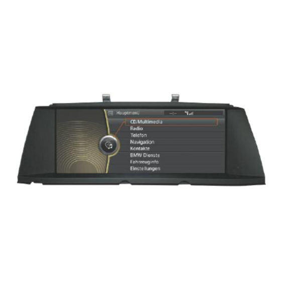
The new display delivers a crisp and improved picture quality compared to the previous system. The graphic layout of the user interface has been totally redesigned. The rear view of the F01/F02 control display is shown in the following with the two con- nections. Front view of control display F01/F02... -
Page 30: Controller
Controller The second most inportant hardware component of the BMW iDrive system is the controller. The new controller has been completely redesigned compared to the CCC controller. The most noticeable new feature of the CIC controller are the seven direct access buttons. - Page 31 Direct access button for Main menu Direct access button for Options sub-menu Direct access button for CD/Multimedia Direct access button for Navigation Direct access button for Radio Direct access button for Telephone Direct access button to go Back F01 Audio Systems...
-
Page 32: Cd/Multimedia
(metadata). This takes place as a supplementary function to the conversion process from Digital Audio CD to a WMA file. A storage space of 4 GB is reserved for this purpose on the CIC-internal hard disk. CD/Multimedia sub-menu with “Music collection” checked F01 Audio Systems... -
Page 33: Storing Music Data On The Hdd
• Copying data via the CD/DVD drive • Copying data from the USB Index Explanation Index Explanation DVD/CD ROM with compressed audio data Hard disk (HDD) (WMA, CDA, MP3, AAC) Commercially available audio CDs USB stick (Compact Disk Digital Audio CDA) F01 Audio Systems... -
Page 34: Rip Function
After the conversion process the files will be displayed and can now be selected individually by using the music search function. Start of rip function for a loaded Digital Audio CD Music data (WMA) of a Digital Audio CD stored in the music collection F01 Audio Systems... -
Page 35: Copying Data Via The Cd/Dvd Drive
CD/DVD ROM. If the CD/DVD ROMs are untitled, they will be stored as "Audio-CD 1", "Audio-CD 2", etc. To facilitate identification, a folder icon is shown next to the file folder. Copying a music file from a CD-ROM F01 Audio Systems... -
Page 36: Copying Data From The Usb
This makes a subsequent search for a music file virtually impossible. Copying USB music file using the import/export music feature USB Import/export interface in glove compartment of the F01/F02 F01 Audio Systems... - Page 37 USB in the glove compartment. Note: The USB interface in the glove compartment is only intended for the import and export of data (music or personal profiles) to and from the vehicle. F01 Audio Systems...
-
Page 38: File System
Digital Audio CD. All music download portals allow the creation of a Digital Audio CD for the downloaded music track. However, the number of copies that can be created is limited by licensing legislation. F01 Audio Systems... -
Page 39: Data Saving (Backup)
Vehicle Owner's Manual. For copyright reasons, the service personnel are not WARNING!!! permitted to perform the data backup for the customer. The service personnel, can, however, instruct the customer on how to perform the backup procedure. F01 Audio Systems... -
Page 40: Music Search
An example of how these metafile or meta information could appear is shown below: Music search Search for: Example Genre Rock Artist Queen Album Greatest Hits II Track A Kind Of Magic Music collection menu with a stored album selected F01 Audio Systems... - Page 41 Note: Albums with newly released metadata at the time of vehicle delivery will no longer be identified. The music track database would require a permanent link with the server in order to keep this data up to date and this is not possible. F01 Audio Systems...
- Page 42 The information about music CDs (Digital Audio CDs) released after the vehicle delivery will not be found in the vehicle's music track database. Note: If the metadata is not found because the Gracenote database in the CIC is outdated, the tracks will not be recognized. F01 Audio Systems...
-
Page 43: Updating The (Gracenote ) Database
To keep the entire contents of the music track database (Gracenote ) up to date, ® BMW Service is equipped with the latest CD of the music track database (Gracenote ® This update takes place in connection with the media package, which also contains the Gracenote Update CD. -
Page 44: Radio
The former layout of the “All stations" list in the form displayed by the CCC has been replaced in the CIC by a list layout. FM menu "All stations" in CIC as list FM menu "All stations" in CCC Manual station search in a CCC system Manual station search in a CIC system F01 Audio Systems... -
Page 45: Am Stations
A double tuner has now made it possible to receive the "All stations" list in the AM range. However, no station information can be displayed because the RDS data is not transmit- ted for AM. AM stations list AM stations manual setting F01 Audio Systems... -
Page 46: Iboc
Under the menu item "Stored stations", the required stations from all frequency ranges can be stored in a common menu and then selected at a later time. The following frequency bands are available for storage: • FM • AM (SW, MW, LW) • IBOC Stored stations F01 Audio Systems... -
Page 47: Settings Menu
Air conditioning (climate control) Auxiliary heating, auxiliary ventilation Home lights One-touch indicators Lights Daytime driving light Welcome light High beam assistant Door locking Remote control key, lock automatically etc. Luggage compartment lid Adjust opening angle Settings Menu F01 Audio Systems... -
Page 48: Favorite Buttons
• Navigation destinations: However, they must already be stored under “Contacts” or entered from “Last destinations” • Phone numbers A new feature is that it is possible to assign all submenus such as “CD/ multimedia” or selection menus such as “Music collection” or “External devices” to the favorite. F01 Audio Systems... -
Page 49: System Components
A CD changer is no longer offered for the F01/ F02. The single-slot DVD changer is offered on the F01 and F02. The DVD changer can accept up to six disks. The disks are inserted in the unit without the use of a magazine. -
Page 50: Car Information Computer (Cic)
The CIC and the IHKA/audio control panel are connected to the center console unit carrier. Side view of IHKA/audio control panel Index Explanation Index Explanation IHKA/audio control panel Car Information Computer Center console unit carrier F01 Audio Systems... - Page 51 Front view of IHKA/audio control panel of the F01/F02 Index Explanation Index Explanation Selector button for FM and AM Eject button for DVD/CD player MODE button for selecting audio sources Station search/track "forward and back" CD/DVD slot Eight freely selectable Favosites buttons...
- Page 52 The player also has ability to playback video DVDs on the front CID. The video signal is only displayed when the vehicle is stationary with the gear selection in the “Park” postilion. F01 Audio Systems...
-
Page 53: Advantages Of The Car Information Computer
Combining several modules in one enclosure provides the following advantages: • The combination of several systems enhances the functionality • Outstanding software expansion options through suitable software interfaces • Fewer plug connections increases reliability • Less overall package space required for control units F01 Audio Systems... - Page 54 Front view of IHKA/audio control panel of the F01/F02 Index Explanation Index Explanation LVDS signal for the CID; 16-pin connector (K-CAN, audio output AF; violet connector power supply, Rad-on signal) USB connection for glove compartment beige GPS antenna signal connector...
-
Page 55: Lvds Technology
• Runtime differences between the individual lines are avoided • Serial 2-wire LVDS data transmission is now much more cost-effective than 8-wire LVDS technology The main advantage of using serial 2-wire LVDS is the resulting high picture resolution. F01 Audio Systems... -
Page 56: Electrostatic Discharge (Esd)
The following picture illustrates the effects of electrostatic discharge (ESD) on electronic components. Index Explanation ESD symbol (protection measures necessary) ESD damage to a conductor (magnified 5000 times) Effects of ESD (Electrostatic Discharge) on electronic components F01 Audio Systems... -
Page 57: Working On Electronic Components
• The electronic components are placed on the anti-static mat which is also connected to a grounding cable. Anti-static mat Special tool 12 7 192 Index Explanation Anti-static mat Grounding cable for the mat Anti-static cuff Grounding cable for the component F01 Audio Systems... -
Page 58: Cic Components
The functions of the individual components are briefly described in the following pages. The installation and removal instructions for the individual components and the complete CIC control unit are available in TIS (Technical Information System) or the workshop system ISTA. Individual components of the CIC on the F01/F02 Index Explanation Index... -
Page 59: Optical Drive (Cd/Dvd Player)
Although the CD/DVD drive is no longer used for the navigation system (as in CCC), it may be used to update navigation map data from a navigation DVD. DVD player of the CIC Index Explanation Index Explanation Ribbon cable connection, DVD DVD player player to CIC head unit Front panel connection F01 Audio Systems... -
Page 60: Hard Disk Drive
With the development CIC, a hard disk for storing applications (programs) and data is used in a head unit of a BMW vehicle for the first time. A 2.5" hard disk drive with a storage a capacity of 80 GB is installed. -
Page 61: Fixed Components
In the event of defects to some of the components, it may be necessary to replace the entire head unit after submitting a PuMA case. Bottom open view of the CIC components Index Explanation Index Explanation FM/AM double tuner module Application board IBOC decoder FM - RTTI module Yaw rate sensor F01 Audio Systems... -
Page 62: Fan
(located directly below it). The exhaust air cools the cooling fins of the HiFi output stage in the power board as it is routed through a cooling channel out of the unit. CIC system’s Cooling Fan location F01 Audio Systems... -
Page 63: Gps Receiver Module
The graphic shows the size of the GPS receiver module compared to the main connection plug of the head unit. Index Explanation GPS receiver module CIC main connection plug CIC system’s GPS receiver size compared to the Main Connector F01 Audio Systems... -
Page 64: Yaw Rate Sensor
The electronic module is soldered into the board directly under the hard disk drive and cannot be replaced separately. The gateway processor has its own control unit address in the BMW diagnosis system. CIC system’s Gateway Processor location F01 Audio Systems... -
Page 65: Analog Tuner Modules
The RTTI messages are used by the navigation system for displaying congestion and traffic information in the form of pictograms. FM tuner module component location in the CIC Index Explanation FM/A M double tuner module FM-RTTI module Black FAKRA connector below the CIC heat sink F01 Audio Systems... -
Page 66: Iboc System/Hd Radio
These signals are then routed to the IBOC decoder which adds the digital data stream to the audible music signals. Location of the IBOC decoder in the CIC Index Explanation Index Explanation FM/AM antenna connection FM/AM double tuner module FM-RTTI module IBOC decoder F01 Audio Systems... - Page 67 Multicast is not sup- ported on AM. The content of the digitally broadcast station is the same as that of the analog station. HD radio plays AM radio stations in near-FM quality and FM radio stations in near-CD quality. F01 Audio Systems...
-
Page 68: Cic Application Board With Processors
The unit interfaces with the vehicle’s electrical system (power supply, MOST link, etc.) through the main connector. Index Explanation Heat sink Power board Main connector of the CIC CIC Main Board and Heat Sink Location F01 Audio Systems... -
Page 69: Amplifiers And Speakers
• HiFi system (Standard) • Top-HiFi system. (Option) The HiFi system is the standard audio equipment for the F01/F02 . The HiFi system is equipped with a 8-channel amplifier with digital equalizer. However only 7 of the 8 channels are used in the HiFi system. - Page 70 The following chart explains the two available sound systems for the F01/F02: HiFi system Top-HiFi system 2 - woofers (2 Ohm) 2 - woofers (2) Number of speakers 5 - mid-range speakers (4) 7 - mid-range speakers (4) 5 - tweeters (4 Ohm)
-
Page 71: Hifi Speaker System
HiFi Speaker System The digital 7-channel HiFi amplifier is supplied by Lear. The HiFi system consists of a HiFi amplifier with the 12 speakers. This system is fitted as standard on the F01/F02. HiFi Speaker System on the F01/F02 Index... -
Page 72: Hifi Amplifier
The HiFi amplifier is located at the rear left of the luggage compartment behind the side panel trim. HiFi amplifier Index Explanation Index Explanation Connection for audio signals, K-CAN Safety fuse and control signals Connection for central bass speakers and power supply F01 Audio Systems... -
Page 73: Top-Hifi Speaker System F01/F02
Top-HiFi Speaker System The digital 10-channel Top-HiFi amplifier is also supplied by Lear. The 16 speaker Top-HiFi system is available as the premium option. Top-HiFi Speaker System F01/F02 Index Explanation Index Explanation Tweeter, front right door Tweeter, rear window shelf, left... -
Page 74: Top-Hifi Amplifier
The Top-HiFi amplifier supports playback of multichannel signals in 5.1 format. The signals are output in 7.2 format (seven mid-range/treble channels and two central bass channels). Top-HiFi amplifier Index Explanation Index Explanation MOST connection Power supply, audio signals to speakers Reserved for load/logic separation, 10th channel preparation F01 Audio Systems... - Page 75 The Top-HiFi amplifier supports Dolby Pro Logic II for calculating the spatial sound information from an existing stereo signal. This process replaces Logic 7 known from other BMW vehicles. A surround sound effect can be computed from the stereo signal, which consists only of a left and right channel.
- Page 76 • one central bass speaker under each of the front seats. The Top-HiFi amplifier is located in the rear left of the luggage compartment behind the side panel trim. It is cooled by it’s own cooling fan. Top-HiFi amplifier with additional fan F01 Audio Systems...
-
Page 77: Antenna System Overview
Antenna System Overview Depending on the optional equipment, F01/ F02 vehicles are equipped with different antennal systems: • FM/AM radio with IBOC system (rear window antennas) • Roof antenna for SDARS satellite radio • Navigation system (roof antenna) • Remote control services (rear window antenna) •... - Page 78 F01/F02 Antenna System Index Explanation Index Explanation Bluetooth antenna AM restrictor HBL filter (HBL = additional brake light) FM rejector circuit, right Antenna amplifier with diversity module FM rejector circuit, left and remote control service (FBD) Roof antenna (GPS receiver for navigation,...
-
Page 79: Antenna Diversity Module With Amplifier
The antennal amplifier also supports the frequencies of the weatherband. Weatherband is transmitted over seven channels in the frequency range from 162.400 MHz to 162.550 MHz. The weatherband tuner is incorporated in the FM module of the head unit. F01/F02 Antenna Diversity module with Antenna Amplifier Index Explanation Index... -
Page 80: Fm Antenna Diversity
FM Antenna Diversity In the F01/F02, an FM antenna diversity is standard equipment. The FM antenna diversity comprises: • FM1, FM2 and FM3 antennas • FM antenna amplifier with diversity module The FM1 to FM3 antennas route their RF signal to the antenna amplifier in the antenna diversity module. -
Page 81: Selection Of The Individual Antennas (Diversity Function)
• AM mode is active, or the FM1 antenna is selected, when U s = 0 V. • Diversity mode is active at U s = 5 V. • The changeover in diagnosis mode to the next antenna takes place by 8 V pulses. F01 Audio Systems... -
Page 82: Am Diversity
(FBD) and the nine antennas for comfort access (four antennas on the outside and five in the interior). Note: For detailed Information on the antennas system refer to the F01/F02 “Central locking”, “Comfort Access” and “Car Access System” Training Material. -
Page 83: Hbl Filter
Index Explanation HBL filter - connection to additional brake light and for powering the diversity module with antenna amplifier Securing screw with ground connection HBL filter, connection to vehicle wiring harness HBL (high level brake light) filter F01 Audio Systems... -
Page 84: Am Restrictor
AM Restrictor AM reception has been improved on the F01/F02. Due to the great distances with relatively few radio broadcasting towers, in less populated areas of the US AM radio is more accessible than FM radio. Interference frequencies from the vehicle electrical system pose reception problems in terms of the quality of AM radio. -
Page 85: Roof Antenna
The roof antenna includes the following components: • Mobile phone antenna • Telematics Control Unit (TCU) telephone antenna • GPS antenna • SDARS satellite radio reception antenna F01/F02 Roof antenna Index Explanation Index Explanation Telephone antennas for SDARS signal, satellite and terrestrial... -
Page 86: Sdars Satellite Tuner
• Digital reception of music, news and talk stations. • Wide choice of available music genres. • No commercial breaks. • Digital signal transmission provides greater immunity to external interference. SDARS control unit Index Explanation Index Explanation SDARS signal MOST (pink connector) Power supply F01 Audio Systems... - Page 87 Blocked SDARS channels If a channel that is not yet subscribed is selected, the request to register with the provider Sirius with the ESN number of the SDARS module will be shown. Request to contact the service provider F01 Audio Systems...
- Page 88 (see picture below). Otherwise, repeat the previous steps. After successfully enabling the channels, on selection, the diskette symbol appears to the right next to the station. It indicates that the station can now be stored in the “All channels” list. SDARS successfully enabled F01 Audio Systems...
- Page 89 The ESN number is always shown in the “Options menu” of the satellite radio. ESN number F01 Audio Systems...
-
Page 90: External Audio Sources
DVD Changer The 6-DVD changer is offered as part of the ZPS Premium Sound Package on the F01/F02 and it is located above the glove compartment behind the dashboard trim panel. A CD Changer is no longer offered. The DVD changer forms part of the MOST network. - Page 91 MOST. Here it is converted to analog data and output through the HiFi amplifier and the speakers. If the Top-HiFi system option is installed, the decoded audio data is sent directly to the Top-HiFi amplifier through the MOST. F01 Audio Systems...
- Page 92 The DVD changer is located above the glove compartment, concealed behind the interior trim equipped with a flap mechanism. The following picture shows the location of the DVD changer with the interior trim open. Single-slot DVD changer is located behind dashboard trim panel above the glove compartment F01 Audio Systems...
-
Page 93: Usb/Audio Interface
Media Transfer Protocol (MTP) is currently not supported. MP3 players that use MTP are therefore not supported. More information on the protocols used can be obtained from the operating instructions of the mass storage device. F01 Audio Systems... - Page 94 FAT file system. If more than one partition (logical drive) has been set up on the device, only the first partition is supported. The USB mass storage device cannot be accessed if the files are password-protected or are subject to Digital Rights Management (DRM). F01 Audio Systems...
-
Page 95: Ipod ® Connection
Audio jack plug, the iDrive cannot be used to operate the device. AUX-in connection (USB/jack 3.5 mm) of option 6FL in the center console of the F01/F02 Note: USB hard drives must not be connected to the USB interface due to their high power draw. -
Page 96: Usb/Audio Interface" Components
• Bluetooth interface with hands-free mode and phone book • Basic voice input and activation system through the telephone ULF-SBX High connections Index Explanation Index Explanation Bluetooth connection (Not in US) MOST connection 54-pin connector USB connection F01 Audio Systems... - Page 97 • Maximum data rate: 12 Mbit/s • Voltage: 5 V • Current: 500 mA The ULF-SBX High is located in the luggage compartment on the left-hand side. Location of interface box (ULF-SBX-High) on rear left in luggage compartment of F01/F02 Index Explanation Index...
-
Page 98: Usb Hub
(black connector) USB connection for base plate Power supply for the USB hub of the Smartphone audio line (black connector) (neutral color connector) Note: The USB hub is only used if the vehicle has the Smartphone Integration option. F01 Audio Systems... -
Page 99: Audio Jack
The USB hub on the F01/F02 is installed behind the trim panel for the left-hand B-pillar. It is installed in the same place on both right-hand drive and left-hand drive vehicles. Location of USB hub at left-hand B-pillar Audio Jack The audio jack is used for connecting an external audio source such as an MP3, cassette or CD player using a 3.5 mm jack plug. -
Page 100: Smartphone Integration
The electronic control module is installed in the base plate of the phone cradle. The link to the USB hub and AUX-In connection are already integrated in the vehicle wiring harness. Smartphone - iPhone with matching snap-in adapter F01 Audio Systems... - Page 101 The following illustration shows the arrangement of the individual components on the base plate for the Smartphone Integration. Index Explanation Base plate connection to roof antenna (black connection) USB connection from base plate to USB hub (blue connector) 18-pin plug connector: (power supply, cradle-on, AUX-AF signals) F01 Audio Systems...
-
Page 102: Audio Data Control Line
Explanation Index Explanation USB connection: 18-pin plug connector of base plate Distribution of the USB supply (power supply, cradle-on, voltage and data lines over two AUX-AF signals) gold-plated pin housings with shielding Antennal connection to roof antenna F01 Audio Systems... -
Page 103: Service Information
• The “Service menu” is now added as the last submenu to Settings Four selection menus are available in the Service menu of the CIC: • Navigation • Telephone and BMW Service • TV (Not for US) • Gracenote ®... -
Page 104: Navigation
Map version Map Database: 1.067 Map version number Database: 1.067 Location entry Location Entry: Entry Loop same as destination entry Voice output test Note: Although it appears in the Service menu, TV is not available on US vehicles. F01 Audio Systems... -
Page 105: Telephone And Bmw Service
Telephone and BMW Service CIC Service menu with Telephone and BMW Service selected Telephone Screen content (example) Explanation BT Name BMW 57502 Bluetooth name of BMW vehicle for pairing 51 dBm GSM signal level of built-in telephone module Mobile Country Code + Mobile Network Code;... - Page 106 • Channel information (transmission standard, bandwidth and program name) • DVB-T parameter (modulation type, analog, digital TV distinction) • Antenna information (field strength in dBµV (Decibel micro Volt ) Note: Although it appears in the Service menu, TV is not available on US vehicles. F01 Audio Systems...
-
Page 107: Gracenote
No data is added to unrecognized music tracks. The update only serves the purpose of identifying music tracks in connection with future music data storage converted with the aid of the rip function. The sub-menu for Gracenote/Start installation under the Service menu F01 Audio Systems... -
Page 108: Resetting The Cic
Programming the CIC is done with the use of the respective optical testing and programming interface modules. The interface modules OP(P)S or ICOM (A+B) are simultaneously connected to the OBD interface and to the MOST interface of the vehicle. F01 Audio Systems...