Table of Contents
Advertisement
Quick Links
Advertisement
Table of Contents

Related Manuals for Contec DIO-0808L-PCI


Summary of Contents for Contec DIO-0808L-PCI
- Page 1 PC-HELPER Digital I/O Board for PCI DIO-0808L-PCI User’s Guide CONTEC CO.,LTD.
- Page 2 Check Your Package Thank you for purchasing the CONTEC product. The product consists of the items listed below. Check, with the following list, that your package is complete. If you discover damaged or missing items, contact your retailer. Product Configuration List...
-
Page 3: Trademarks
No part of this document may be copied or reproduced in any form by any means without prior written consent of CONTEC CO., LTD. CONTEC CO., LTD. makes no commitment to update or keep current the information contained in this document. The information in this document is subject to change without notice. -
Page 4: Table Of Contents
Plugging the Board ........................15 Step 3 Installing the Hardware ......................16 Turning on the PC ........................16 Setting with the Found New Hardware Wizard ................ 16 Step 4 Initializing the Software ......................19 When Using API-DIO(WDM) ....................19 DIO-0808L-PCI... - Page 5 Clearing the Interrupt Status and Interrupt Signal ..............37 ABOUT SOFTWARE DVD-ROM Directory Structure ....................... 39 About Software for Windows ......................40 Accessing the Help File ......................40 Using Sample Programs ......................40 Uninstalling the Driver Libraries ....................41 DIO-0808L-PCI...
- Page 6 ABOUT HARDWARE Hardware specification ........................43 Block Diagram ..........................45 DIO-0808L-PCI...
- Page 7 DIO-0808L-PCI...
-
Page 8: Before Using The Product
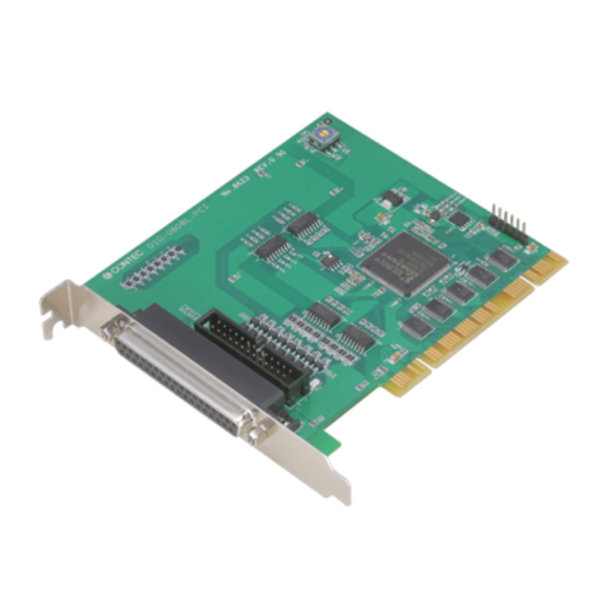
This product is a PCI bus-compliant interface board that extends the digital signal I/O functions of a PC. DIO-0808L-PCI is a 12 - 24VDC opto-coupler isolated type with opto-coupler isolated input 8ch and opto-coupler isolated open-collector output 8ch. You can use all of the input signals as interrupt inputs. -
Page 9: Support Software
Windows 8, 7, Vista, Windows XP, Server 2008, Server 2003, 2000 Adaptation language Visual Basic, Visual C++, Visual C# You can download the updated version from the CONTEC’s Web site (http://www.contec.com/apipac/). For more details on the supported OS, applicable language and new information, please visit the CONTEC’s Web site. DIO-0808L-PCI... -
Page 10: Cable & Connector (Option)
Screw Terminal (M2.5 x 37P) DTP-4C *1 *1 A PCB37P or PCB37PS optional cable is required separately. *2 "Spring-up" type terminal is used to prevent terminal screws from falling off. * Check the CONTEC’s Web site for more information on these options. DIO-0808L-PCI... -
Page 11: Customer Support
You can download updated driver software and differential files as well as sample programs available in several languages. Note! For product information Contact your retailer if you have any technical question about a CONTEC product or need its price, delivery time, or estimate information. Limited Three-Years Warranty CONTEC Interface boards are warranted by CONTEC CO., LTD. -
Page 12: Safety Precautions
WARNING indicates a potentially hazardous situation which, if not avoided, could WARNING result in death or serious injury. CAUTION indicates a potentially hazardous situation which, if not avoided, may CAUTION result in minor or moderate injury or in property damage. DIO-0808L-PCI... -
Page 13: Handling Precautions
Even when using the product continuously, be sure to read the manual and understand the contents. Do not modify the product. CONTEC will bear no responsibility for any problems, etc., resulting from modifying this product. Regardless of the foregoing statements, CONTEC is not liable for any damages whatsoever (including damages for loss of business profits) arising out of the use or inability to use this CONTEC product or the information contained herein. -
Page 14: Environment
(3) Store the package at room temperature at a place free from direct sunlight, moisture, shock, vibration, magnetism, and static electricity. Disposal When disposing of the product, follow the disposal procedures stipulated under the relevant laws and municipal ordinances. DIO-0808L-PCI... - Page 15 1. Before Using the Product DIO-0808L-PCI...
-
Page 16: Setup
For setting up software other than API-PAC(W32), refer to the manual for that software. See also the following parts of this manual as required. This chapter Step 2 Setting the Hardware This chapter Step 3 Installing the Hardware Chapter 3 External Connection Chapter 6 About Hardware DIO-0808L-PCI... -
Page 17: Using The Board Under An Os Other Than Windows
Using the Board under an OS Other than Windows For using the board under an OS other than Windows, see the following parts of this manual. This chapter Step 2 Setting the Hardware Chapter 3 External Connection Chapter 6 About Hardware DIO-0808L-PCI... -
Page 18: Step 1 Installing The Software
(3) Click on the [Install Development or Execution Environment] button. * When using the Windows 8, 7, Vista, driver is automatically installed. CAUTION Before installing the software in Windows 8, 7, Vista, Server 2008, Server 2003, XP, and 2000, log in as a user with administrator privileges. DIO-0808L-PCI... - Page 19 * Clicking the [API-DIO] button under the “Detail” displays detailed information about API-DIO(WDM) and API-DIO(98/PC). Run the installation (1) Complete the installation by following the instructions on the screen. (2) The Readme file appears when the installation is complete. DIO-0808L-PCI...
-
Page 20: Step 2 Setting The Hardware
Parts of the Board and Factory Defaults Figure 2.1. shows the names of major parts on the board. Note that the switch setting shown below is the factory default. - Board ID setting switch DIO-0808L-PCI BOARD ID BOARD ID - Interface connector (CN1) Figure 2.1. -
Page 21: Setting The Board Id
Setting Procedure To set the board ID, use the rotary switch on the board. Turn the SW1 knob to set the board ID as shown below. BOARD ID Factory setting: (Board ID = 0) Figure 2.2. Board ID Settings (SW1) DIO-0808L-PCI... -
Page 22: Plugging The Board
Be sure that the personal computer power is turned off. Make sure that your PC or expansion unit can supply ample power to all the boards installed. Insufficiently energized boards could malfunction, overheat, or cause a failure. Power supply from the PCI bus slot at +5V is required. DIO-0808L-PCI... -
Page 23: Step 3 Installing The Hardware
In this case, you must check the resource settings. Setting with the Found New Hardware Wizard (1) The “Found New Hardware Wizard” will be started. Select “No, not this time” and then click the “Next” button. DIO-0808L-PCI... - Page 24 When the model name of hardware is displayed, select “Install the software automatically [Recommended]” and then click on the “Next” button. Source folder The setup information (INF) file is contained in the following folder on the bundled DVD-ROM. \INF\Wdm\Dio \INF\Wdm\DIO DIO-0808L-PCI...
- Page 25 2. Setup * The name of the board you have just added is displayed. - DIO-0808L-PCI You have now finished installing the hardware. DIO-0808L-PCI...
-
Page 26: Step 4 Initializing The Software
- DIO-0808L-PCI (2) The installed hardware appears under the CONTEC Devices node. Open the CONTEC Devices node and select the device you want to setup (the device name should appear highlighted). Click [Properties]. DIO-0808L-PCI... - Page 27 - DIO-0808L-PCI The initial device name that appears is a default value. You can use this default name if you wish. Make sure that you do not use the same name for more than one device.
-
Page 28: Step 5 Checking Operations With The Diagnosis Program
Connect the board to a remote device to text the input/output and check the execution environment. For this board, prepare an external power supply (12 - 24VDC). Set the board in the default factory. To connect the external device, see Chapter 3 “External Connection”. DIO-0808L-PCI... -
Page 29: Using The Diagnosis Program
2. Setup Using the Diagnosis Program Starting the Diagnosis Program for Use of API-DIO(WDM) Click the [Diagnosis] button on the device property page to start the diagnosis program. DIO-0808L-PCI... - Page 30 * The name of the board you have just added is displayed. - DIO-0808L-PCI To use the wait time control feature, click on the [Wait Configuration] button. Use the feature when the wait time based on the DioWait or DioWaitEx function is not normal.
- Page 31 Before executing diagnosis report output, unplug the cable from the board. * The name of the board you have just added is displayed. - DIO-0808L-PCI Click on [Show Diagnosis Report]. (2) A diagnosis report is displayed as shown below. * The name of the board you have tested is displayed.
-
Page 32: Setup Troubleshooting
Turn off the power to your PC, then unplug the board. Restart the OS and delete the board settings of API-TOOL Configuration. Turn off the PC again, plug the board, and restart the OS. Let the OS detect the board and use API-TOOL Configuration to register board settings. If your problem cannot be resolved Contact your retailer. DIO-0808L-PCI... - Page 33 2. Setup DIO-0808L-PCI...
-
Page 34: External Connection
- Connector used 37-pin D-SUB, female connector DCLC-J37SAF-20L9(mfd. by JAE) Thumb screw : UNC#4-40(inch screw) - Applicable connectors 17JE-23370-02(D8C) (mfd. by DDK, Male) FDCD-37P (mfd. by HIROSE, Male) DC-37P-N (mfd. by JAE, Male) Figure 3.1. Interface Connector and Applicable Cable Connector DIO-0808L-PCI... -
Page 35: Connector Pin Assignment
These pins are common to 8 output signal pins. Connect the negative side of the external power supply. These pins are common to 8 output signal pins. Others This pin is left unconnected. Figure 3.2. Pin Assignments of Interface Connector (CN1) DIO-0808L-PCI... -
Page 36: Relationships Between Logical Ports/Bits And Connector Signal Pins
I-07 I-06 I-05 I-04 I-03 I-02 I-01 I-00 Input logical port O-07 O-06 O-05 O-04 O-03 O-02 O-01 O-00 Output logical port Notes : I-xx represents the input signal. O-xx represents the output signal. [xx] represents the logical bit. DIO-0808L-PCI... -
Page 37: Connecting Input Signals
I-00 (CN1 : 2pin) 12 - 24VDC Switch When the switch is ON, the corresponding bit contains 1. When the switch is OFF, by contrast, the bit contains 0. Figure 3.4. An Example to use Input I-00 DIO-0808L-PCI... -
Page 38: Connecting Output Signals
If this is the case, turn of the power to the PC and the external power supply and wait for a few minutes, then turn them on back. CAUTION When the PC is turned on, all output are reset to OFF. DIO-0808L-PCI... -
Page 39: Connection To The Led
Figure 3.6. An Example to use Output O-00 Example of Connection to TTL Level Input External power supply 12 - 24VDC Input board Output plus common 2k Output TTL level input Output minus common Figure 3.7. Connection Example of Output and TTL level Input Signal DIO-0808L-PCI... -
Page 40: Connecting The Sink Type Output And Sink Output Support Input
12 - 24VDC Output board Input board Input plus common Output plus common Output (sink type) Input (Compatible with sink output) Output minus common Figure 3.8. Example of Connecting the Sink Type Output and Sink Output Support Input DIO-0808L-PCI... - Page 41 3. External Connection DIO-0808L-PCI...
-
Page 42: Function
When “0” is output to the relevant bit, in contrast, the corresponding transistor is set to “OFF”. CAUTION When the PC is turned on, all output are reset to 0 (OFF). Monitoring Output Data The <DIO-0808L-PCI> can read the state of the data currently being output without affecting the output data. DIO-0808L-PCI... -
Page 43: Digital Filter
4. Function Digital Filter Using this feature, The <DIO-0808L-PCI> can apply a digital filter to every input pin, thereby preventing the input signal from being affected by noise or chattering. Digital Filter Function Principle The digital filter checks the input signal level during the sampling time of the clock signal. When the... -
Page 44: Interrupt Control Function
4. Function Interrupt Control Function The <DIO-0808L-PCI> can use all of the input signals as interrupt request signals. This product can generate an interrupt request signal to the PC when the input signal change from High to Low or from Low to High. - Page 45 4. Function DIO-0808L-PCI...
-
Page 46: About Software
|––WDM |––Win2000 |––Win95 |––linux Linux driver file |––cnt |––dio |––…… | ––Readme Readme file for each driver | ––Release Driver file on each API-TOOL |––API_NT (For creation of a user-specific install program) |––API_W95 | ––UsersGuide Hardware User's Guide(PDF files) DIO-0808L-PCI... -
Page 47: About Software For Windows
Use these sample programs as references for program development and operation check. Running a Sample Program (1) Click on the [Start] button on the Windows taskbar. (2) For the API-DIO(WDM), from the Start Menu, select “Programs” – “CONTEC API-PAC(W32)” – “DIOWDM” – “SAMPLE…”. (3) A sample program is invoked. -
Page 48: Uninstalling The Driver Libraries
[Device Manager] tab. (You can also open Device Manager by right clicking on My Computer and selecting Properties.) 2. All of the hardware that uses the API-TOOL(WDM) driver is registered under the CONTEC Devices tree. Open the device tree, select the hardware to uninstall, and then right-click the hardware. - Page 49 < Uninstall the device driver > Use [My Computer] - [Control Panel] - [Add and Remove Applications] to uninstall the device driver. Select [Windows driver package - CONTEC (****)] and then click [Change/Remove]. * "***" contains the driver category name (caio, ccnt, cdio, csmc, etc.).
- Page 50 Residual voltage with 0.5V or less (Output current50mA), 1.0V or less (Output current100mA) output on Surge protector Zener diode RD47FM(NEC) or equivalent to it Response time Within 200sec Data “0” and “1” correspond to the High and Low levels, respectively. DIO-0808L-PCI...
- Page 51 37 pin D-SUB connector [F (female) type] Connector DCLC-J37SAF-20L9E [mfd by JAE] or equivalent to it Weight 84.4g Board Dimensions 121.69(L) The standard outside dimension (L) is the distance from the end of the board to the outer surface of the slot cover. [mm] DIO-0808L-PCI...
- Page 52 6. About Hardware Block Diagram External digital Opto- Input Port 0 coupler (8 channels, Group 0) Control Opto- Circuits coupler & External digital Transistors Output Port 0 (8 channels, Group 1) Interrupt Control Circuit Figure 6.1. Block Diagram DIO-0808L-PCI...
- Page 53 3-9-31, Himesato, Nishiyodogawa-ku, Osaka 555-0025, Japan Japanese http://www.contec.co.jp/ English http://www.contec.com/ Chinese http://www.contec.com.cn/ No part of this document may be copied or reproduced in any form by any means without prior written consent of CONTEC CO., LTD. [07042014] Management No. NA03525 Parts No. LYRS561...
- Page 54 About Terminal 부 록 사용자 메뉴얼 ※ Terminal 및 Cable은 옵션 품목입니다.
- Page 55 About Terminal Board to Terminal Cable Connection ( Option ) < DIO – 0808L-PCI > Comon plus pin Comon plus pin for output Port < XTB – 20H > for Input Port O-07 I-07 O-06 I-06 O-05 I-05 output O-04 Input I-04 Port...
- Page 56 About Terminal Features • Terminal Pitch 7.0㎜ • Easy for working and Maintenance · As it uses hinge-typed transparent T/B cover, it is easy to work and maintain. · As it is designed to have a DIN Rail mounting structure and has a hole for securing on the mounting plate, it is very easy to install it.
- Page 57 About Terminal...