Table of Contents
Advertisement
Advertisement
Table of Contents

Related Manuals for Asus Pro WS X570-ACE


Summary of Contents for Asus Pro WS X570-ACE
- Page 1 Pro WS X570-ACE...
- Page 2 Product warranty or service will not be extended if: (1) the product is repaired, modified or altered, unless such repair, modification of alteration is authorized in writing by ASUS; or (2) the serial number of the product is defaced or missing.
-
Page 3: Table Of Contents
Contents Safety information ...................... iv About this guide ......................iv Package contents ....................... vi ASUS Pro WS X570-ACE specifications summary ..........vi Chapter 1: Product Introduction Before you proceed ................... 1-1 Motherboard overview ................1-1 Central Processing Unit (CPU) ............... 1-11 System memory .................. -
Page 4: Safety Information
Safety information Electrical safety • To prevent electrical shock hazard, disconnect the power cable from the electrical outlet before relocating the system. • When adding or removing devices to or from the system, ensure that the power cables for the devices are unplugged before the signal cables are connected. If possible, disconnect all power cables from the existing system before you add a device. -
Page 5: Conventions Used In This Guide
Refer to the following sources for additional information and for product and software updates. ASUS website The ASUS website (www.asus.com) provides updated information on ASUS hardware and software products. Optional documentation Your product package may include optional documentation, such as warranty flyers, that may have been added by your dealer. -
Page 6: Package Contents
2400 / 2133 MHz, un-buffered memory Dual channel memory architecture * Refer to www.asus.com for the Memory QVL (Qualified Vendors List). Gen AMD Ryzen™ Processors - 2 x PCI Express 4.0 x16 slots (single at x16 or dual at x8/x8 mode) Gen AMD Ryzen™... - Page 7 ASUS Pro WS X570-ACE specifications summary Integrated Graphics in the AMD Ryzen™ with Radeon™ Vega Graphics Processors Multi-VGA output support: DisplayPort/HDMI ports Graphics Supports DisplayPort 1.2 with max. resolution 4096 x 2160@ 60Hz Supports HDMI 2.0b with max. resolution 4096 x 2160 @24Hz / 2560 x 1600 @ 60Hz and 2 Gen AMD Ryzen™...
- Page 8 - ASUS Server Management Application ASUS SafeSlot - Protect your graphics card Investment ASUS 5X Protection III - ASUS LANGuard: Protects against LAN surges, lightning strikes and static- electricity discharges! - ASUS Overvoltage Protection: World-class circuit-protecting power design - ASUS Stainless-Steel Back I/O: 3X corrosion-resistance for greater durability!
- Page 9 ASUS Pro WS X570-ACE specifications summary Gen AMD Ryzen™ Processors - 3 x USB 3.2 Gen 1 ports (2 ports at back panel[blue], 1 port at mid-board) Gen AMD Ryzen™ / 2 and 1 Gen AMD Ryzen™ with Radeon™ Vega Graphics Processors - 3 x USB 3.2 Gen 1 ports (2 ports at back panel[blue], 1 port at mid-board)
- Page 10 1 x Debug Header 256 Mb Flash ROM, UEFI AMI BIOS, PnP, SMBIOS 3.2, ACPI 6.2, Multi- language BIOS, ASUS EZ Flash 3, CrashFree BIOS 3, F11 EZ Tuning Wizard, BIOS F6 Qfan Control, F3 My Favorites, Last Modified log, F12 PrintScreen, F9 Search...
-
Page 11: Before You Proceed
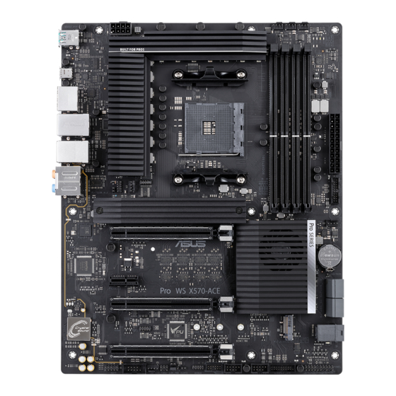
Failure to do so may cause severe damage to the motherboard, peripherals, or components. Motherboard overview Place this side towards the rear of the chassis Unplug the power cord before installing or removing the motherboard. Failure to do so can cause you physical injury and damage motherboard components. ASUS Pro WS X570-ACE... -
Page 12: Layout Contents
1.2.1 Layout contents Connectors/Jumpers/Slots Page ATX power connectors (24-pin EATXPWR, 8-pin EATX12V) AMD AM4 CPU socket DDR4 DIMM slots CPU, CPU optional, chassis, and AIO pump fan connectors (4-pin CPU_FAN, 4-pin CPU_OPT, 4-pin CHA_FAN1~3, 4-pin AIO_PUMP FAN) USB 3.2 Gen 1 connector (20-1 pin U32G1_12; U32G1_34) SATA 6Gb/s connector (7-pin SATA6G_1-4) Mini-SAS HD connector (U.2) System panel connector (20-3 pin PANEL) USB 2.0 connector (10-1 pin USB1112; USB1314) 10. Node connector (12-1 pin NODE) 11. Thermal Sensor connector (2-pin T_SENSOR) 12. Clear RTC RAM (2-pin CLRTC) 13. Clear LAN Password (3-pin LAN_PWD) 14. Serial port connector (10-1 pin COM) 15. Front panel audio connector (10-1 pin AAFP) 16. PCI Express 4.0/3.0 x16 slots 17. PCI Express 3.0/2.0 x1 slots 18. M.2 sockets (M.2_1(SOCKET3); M.2_2 (SOCKET3)) ATX power connectors (24-pin EATXPWR, 8-pin EATX12V) EATX12V Correctly orient the ATX power supply plugs into these connectors and push down firmly until the connectors... - Page 13 U32G1_34) PIN 1 USB3+5V Connect a USB 3.2 Gen 1 module to any of these USB3+5V IntA_P1_SSRX- IntA_P2_SSRX- IntA_P1_SSRX+ connectors for additional USB 3.2 Gen 1 front or rear IntA_P2_SSRX+ IntA_P1_SSTX- panel ports. These connectors comply with USB 3.2 IntA_P2_SSTX- IntA_P1_SSTX+ IntA_P2_SSTX+ IntA_P1_D- Gen 1 specifications and provides faster data transfer IntA_P2_D- IntA_P1_D+ IntA_P2_D+ speeds of up to 5 Gbps, faster charging time for USB- chargeable devices, optimized power efficiency, and backward compatibility with USB 2.0 SATA 6Gb/s connector (7-pin SATA6G_1-4) SATA6G These connectors connect to Serial ATA 6.0 Gb/s hard disk drives via Serial ATA 6.0 Gb/s signal cables. RSATA_TXP RSATA_TXN RSATA_RXN RSATA_RXP ASUS Pro WS X570-ACE...
- Page 14 Mini-SAS HD connector (U.2) The Mini-SAS HD connector allows you to connect a Mini-SAS HD cable to support configurations such as U.2 devices or four SATA devices. System panel connector (20-3 pin PANEL) This connector supports several chassis-mounted functions. • System power LED (4-pin PWR_LED) This 4-pin connector is for the system power LED. Connect the chassis power LED cable to this connector. The system power LED lights up when you turn on the system power, and blinks when the system is in sleep mode. • System power LED (2-pin or 3-1 pin PLED) The 2-pin or 3-1 pin connector is for the system power LED. • Hard disk drive activity LED (2-pin HDD_LED) This 2-pin connector is for the HDD Activity LED. •...
- Page 15 To erase the RTC RAM: PIN 1 Turn OFF the computer and unplug the power cord. Use a metal object such as a screwdriver to short the two pins. Plug the power cord and turn ON the computer. Hold down the <Del> key during the boot process and enter BIOS setup to re-enter data. If the steps above do not help, remove the onboard battery and short the two pins again to clear the CMOS RTC RAM data. After clearing the CMOS, reinstall the battery. Clear LAN Password (3-pin LAN_PWD) LAN_PWD This jumper allows you to clear the LAN password. To erase the LAN Password: Clear Turn OFF the computer and unplug the power cord. Password Move the jumper cap from pins 1-2 (default) to pins 2-3. Keep the cap on pins 2-3 for about 5-10 seconds, then move the cap back to pins 1-2. Plug the power cord and turn ON the computer. ASUS Pro WS X570-ACE...
- Page 16 Serial port connector (10-1 pin COM) This connector is for a serial (COM) port. Connect the serial port module cable to this connector, then install the module to a slot opening at the back of the system chassis. PIN 1 Front panel audio connector (10-1 pin AAFP) This connector is for a chassis-mounted front panel audio I/O module that supports HD Audio standard. Connect one end of the front panel audio I/O module AAFP cable to this connector.
- Page 17 PCIe card PCIe card PCIe card PCIe x16_1 x8 (PCIe 3.0) x8 (PCIe 3.0) PCIe x16_2 PCIe x16_3 x8 (PCIe 4.0) M.2_1 (PCIe Mode) x4 (PCIe 3.0) x4 (PCIe 3.0) x4 (PCIe 3.0) M.2_1 (SATA Mode) Support Support Support M.2_2 (PCIe Mode) x2 (PCIe 4.0) x2 (PCIe 4.0) x2 (PCIe 4.0) M.2_2 (SATA Mode) • We recommend that you provide sufficient power when running CrossFireX™ or SLI ® mode. • Ensure to connect the 8-pin and 4-pin power plugs when running CrossFireX™ or mode. ® • Connect a chassis fan to the chassis fan connectors when using multiple graphics cards for better thermal environment. ASUS Pro WS X570-ACE...
- Page 18 M.2 sockets (M.2_1(SOCKET3); M.2_2 (SOCKET3)) M.2(SOCKET3) These sockets allow you to install M.2 (NGFF) SSD modules. • For 3 Gen AMD Ryzen™ Processors, the M.2_1 supports PCIe 4.0 x4 and SATA modes M key design and type 2242/2260/2280/22110 storage devices. • For 2 and 1 Gen AMD Ryzen™ / 2 and 1 Gen AMD Ryzen™ with Radeon™ Vega Graphics Processors, the M.2_1 supports PCIe 3.0 x4 and SATA modes M key design and type 2242/2260/2280/22110 storage devices. • For AMD X570 chipset, the M.2_2 supports PCIe 4.0 x2 mode M key design and type 2242/2260/2280 storage devices. • The M.2_2 socket shares PCIe lanes with PCIeX1_1; when PCIeX1_1 is occupied, M.2_2 only can only run at PCIE 4.0 x 1. The M.2 SSD module is purchased separately. Chapter 1: Product Introduction...
-
Page 19: Rear Panel Connectors
LAN (RJ-45) port. These ports allow Gigabit connection to a Local Area Network (LAN) through a network hub. LAN port LED indications Activity/Link LED Speed LED ACT/LINK SPEED Status Description Status Description No link 10Mbps connection Orange Linked ORANGE 100Mbps connection Orange (Blinking) Data activity GREEN 1Gbps connection Orange (Blinking Ready to wake Wake up LAN port then steady) from S5 mode HDMI port. This port is for a High-Definition Multimedia Interface (HDMI) connector, and is HDCP compliant allowing playback of HD DVD, Blu-ray, and other protected content. ASUS Pro WS X570-ACE... - Page 20 USB 3.2 Gen 1 Type-A port. These 9-pin Universal Serial Bus (USB) ports are for USB 3.2 Gen 1 devices. • USB 3.2 Gen 1 devices can only be used for data storage. • We strongly recommend that you connect USB 3.2 Gen 1 devices to USB 3.2 Gen 1 ports for faster and better performance from your USB 3.2 Gen 1 devices. USB 3.2 Gen 2 Type-A ports. These 9-pin Universal Serial Bus 3.2 (USB 3.2) ports are for USB 3.2 Gen 2 devices. • USB 3.2 Gen 1/Gen 2 devices can only be used as data storage only. • We strongly recommend that you connect your devices to ports with matching data transfer rate. Please connect your USB 3.2 Gen 1 devices to USB 3.2 Gen 1 ports and your USB 3.2 Gen 2 devices to USB 3.2 Gen 2 ports for faster and better performance for your devices. Optical S/PDIF OUT port. This port allows you to connect amplified speakers, headphones, or Sony/Phillips Digital Interconnect Format (S/PDIF) compliant devices. Audio I/O ports. Refer to the audio configuration table below for the function of the audio ports in 2, 4, 5.1, or 7.1-channel configuration. Audio 2, 4, 5.1, or 7.1-channel configuration Headset Port 4-channel...
-
Page 21: Central Processing Unit (Cpu)
Central Processing Unit (CPU) The motherboard comes with an AM4 socket designed for AMD AM4 Socket for 3 and 2 Gen AMD Ryzen™ / 2 and 1 Gen AMD Ryzen™ with Radeon™ Vega Graphics Processors. Unplug all power cables before installing the CPU. • The AM4 socket has a different pinout design. Ensure that you use a CPU designed for the AM4 socket. • The CPU fits in only one correct orientation. DO NOT force the CPU into the socket to prevent bending the connectors on the CPU and damaging the CPU. • Ensure that all power cables are unplugged before installing the CPU. Installing the CPU Apply the Thermal Interface Material to the CPU heatsink and CPU before you install the heatsink and fan if necessary. ASUS Pro WS X570-ACE 1-11... -
Page 22: System Memory
System memory Overview This motherboard comes with four Double Data Rate 4 (DDR4) Dual Inline Memory Module (DIMM) sockets. The figure illustrates the location of the DDR4 DIMM sockets: Channel Sockets Channel A DIMM_A1 & DIMM_A2 Channel B DIMM_B1 & DIMM_B2 • Start installing the DIMMs in slots A2 and B2. • Always install DIMMs with the same CAS Latency. For an optimum compatibility, we recommend that you install memory modules of the same version or data code (D/C) from the same vendor. Check with the vendor to get the correct memory modules. • The default memory operation frequency is dependent on its Serial Presence Detect (SPD), which is the standard way of accessing information from a memory module. Under the default state, some memory modules for overclocking may operate at a lower frequency than the vendor-marked value. • For system stability, use a more efficient memory cooling system to support a full memory load or overclocking condition. • Visit the ASUS website for the latest QVL. 1-12 Chapter 1: Product Introduction... -
Page 23: Installing A Dimm
Installing a DIMM To remove a DIMM ASUS Pro WS X570-ACE 1-13... - Page 24 1-14 Chapter 1: Product Introduction...
-
Page 25: Managing And Updating Your Bios
Managing and updating your BIOS Save a copy of the original motherboard BIOS file to a USB flash disk in case you need to restore the BIOS in the future. Copy the original motherboard BIOS using the ASUS Update utility. -
Page 26: Asus Ez Flash
2.1.2 ASUS EZ Flash 3 The ASUS EZ Flash 3 allows you to download and update to the latest BIOS through the Internet without having to use a bootable floppy disk or an OS‑based utility. • Ensure to load the BIOS default settings to ensure system compatibility and stability. -
Page 27: Asus Crashfree Bios 3 Utility
2.1.3 ASUS CrashFree BIOS 3 utility The ASUS CrashFree BIOS 3 is an auto recovery tool that allows you to restore the BIOS file when it fails or gets corrupted during the updating process. You can restore a corrupted BIOS file using the motherboard support DVD or a USB flash drive that contains the updated BIOS file. -
Page 28: Bios Setup Program
The BIOS setup screens shown in this section are for reference purposes only, and may not exactly match what you see on your screen. • Visit the ASUS website at www.asus.com to download the latest BIOS file for this motherboard. •... - Page 29 Click to go to Advanced mode Loads optimized Search on the FAQ default settings Click to display boot devices Selects the boot device priority The boot device options vary depending on the devices you installed to the system. ASUS Pro WS X570-ACE 2‑5...
-
Page 30: Advanced Mode
2.2.2 Advanced Mode The Advanced Mode provides advanced options for experienced end‑users to configure the BIOS settings. The figure below shows an example of the Advanced Mode. Refer to the following sections for the detailed configurations. To access the EZ Mode, click EzMode(F7) or press <F7>. Search(F9) Configuration fields Scroll bar... -
Page 31: Menu Bar
This button above the menu bar displays the current settings of your fans. Use this button to manually tweak the fans to your desired settings. Search (F9) This button allows you to search for BIOS items by entering its name, enter the item name to find the related item listing. ASUS Pro WS X570-ACE 2‑7... -
Page 32: Scroll Bar
Move your mouse over this button to show a QR code, scan this QR code on your mobile device to connect to the BIOS FAQ web page of the ASUS support website. You can also scan the following QR code:... -
Page 33: Exit Menu
<Esc>, a confirmation window appears. Select OK to discard changes and exit. Launch EFI Shell from USB drives This option allows you to attempt to launch the EFI Shell application (shellx64.efi) from one of the available USB devices. ASUS Pro WS X570-ACE... - Page 34 2‑10 Chapter 2: BIOS Information...
-
Page 35: Notices
Appendix Notices FCC Compliance Information Responsible Party: Asus Computer International Address: 48720 Kato Rd., Fremont, CA 94538, USA Phone / Fax No: (510)739-3777 / (510)608-4555 This device complies with part 15 of the FCC Rules. Operation is subject to the following two conditions: (1) This device may not cause harmful interference, and (2) this device must accept any interference received, including interference that may cause undesired operation. - Page 36 Compliance Statement of Innovation, Science and Economic Development Canada (ISED) This device complies with Innovation, Science and Economic Development Canada licence exempt RSS standard(s). Operation is subject to the following two conditions: (1) this device may not cause interference, and (2) this device must accept any interference, including interference that may cause undesired operation of the device.
- Page 37 ASUS Recycling/Takeback Services ASUS recycling and takeback programs come from our commitment to the highest standards for protecting our environment. We believe in providing solutions for you to be able to responsibly recycle our products, batteries, other components as well as the packaging materials.
- Page 38 доступний на: www.asus.com/support Cijeli tekst EU izjave o sukladnosti dostupan je na: www.asus.com/support Türkçe AsusTek Computer Inc., bu aygıtın temel gereksinimlerle ve ilişkili Čeština Společnost ASUSTeK Computer Inc. tímto prohlašuje, že toto Yönergelerin diğer ilgili koşullarıyla uyumlu olduğunu beyan eder.
-
Page 39: Asus Contact Information
+1-510-739-3777 +1-510-608-4555 Web site http://www.asus.com/us/ Technical Support Support fax +1-812-284-0883 Telephone +1-812-282-2787 Online support http://qr.asus.com/techserv ASUS COMPUTER GmbH (Germany and Austria) Address Harkort Str. 21-23, 40880 Ratingen, Germany +49-2102-959931 Web site http://www.asus.com/de Online contact http://eu-rma.asus.com/sales Technical Support Telephone +49-2102-5789555 Support Fax... - Page 40 Appendices...