Advertisement
Anleitungen und elektrische Installation CB11
D
Instructions et installation électrique CB11
F
Instructions and electrical set up CB11
GB
Návody a elektrická instalace CB11
CZ
Instrucciones y instalación eléctrica CB11
E
Οδηγίες και ηλεκτρική εγκατάσταση CB11
GR
Útmutatók és elektromos installáció CB11
H
Upute i električne instalacije CB11
HR
Istruzioni e installazione elettrica CB11
I
Instruktie en electrische installatie CB11
NL
Manuais e instalação eléctrica CB11
P
Instrukcja i instalacja elektryczna CB11
PL
Инструкции и электромонтаж CB11
RUS
i
INT
DE
GB
FR
NL
www.liftmaster.com
Email: info@chamberlain.com
AT/BA/BE/BG/CH/CY/CZ/DE/DK/ES/
FR/GB/GR/HR/HU/IE/IS/IT/LU/MT/NL
NO/PL/PT/RO/RU/SE/SI/SK/TR/YU
(+49) 06838-907-172
06838-907-172
0845-602-4285
03.87.95.39.28
020.684.79.78
0678
709438
Advertisement
Table of Contents

Related Manuals for Chamberlain LiftMaster CB11


Summary of Contents for Chamberlain LiftMaster CB11
- Page 1 Upute i električne instalacije CB11 Istruzioni e installazione elettrica CB11 Instruktie en electrische installatie CB11 Manuais e instalação eléctrica CB11 Instrukcja i instalacja elektryczna CB11 Инструкции и электромонтаж CB11 (+49) 06838-907-172 06838-907-172 0845-602-4285 03.87.95.39.28 020.684.79.78 www.liftmaster.com Email: info@chamberlain.com 0678 AT/BA/BE/BG/CH/CY/CZ/DE/DK/ES/ FR/GB/GR/HR/HU/IE/IS/IT/LU/MT/NL NO/PL/PT/RO/RU/SE/SI/SK/TR/YU 709438...
- Page 2 © Chamberlain GmbH 2006, all rights reserved 709438...
-
Page 3: Installation Of The Control Box
ATTENTION IMPORTANT FITTING AND OPERATING INSTRUCTIONS PLEASE START BY READING THESE IMPORTANT SAFETY RULES • SAVE THESE INSTRUCTIONS This safety alert symbol means "Caution" - failure to comply with such an instruction involves risk of personal injury or damage to property. Please read these warnings carefully. This gate drive mechanism is designed and tested to offer appropriately safe service provided it is installed and operated in strict accordance with the following safety rules. - Page 4 Typical configuration of a unit: 1. Motor 2. Control board 3. photocell (active for closing), max. height 200 mm First photocell. 4. photocell (active for opening), max. height 200 mm Second photocell. 5. Flashing light (optional) Important visual information on the movement of the gate. 6.
-
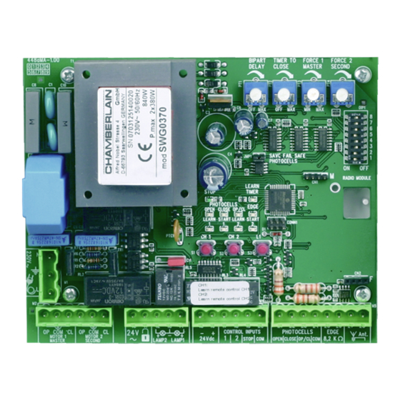
Page 5: Description Of The Leds
CONTROL BOX CONFIGURATION DESCRIPTION OF THE LEDs POINT DESCRIPTION FUNCTION M1, terminals:1,2,3 Feeder cable RED LEDs should be switched off. Indication of faults to be rectified; this does not apply to failsafe photocells not connected. M2, terminals:4,5,6 Drive 1 (master) (see “JUMPER”... - Page 6 CLOSED direction and opens the relay for activating the e-lock for one second. ( Function due to DIP4 the various commercial e-locks available.) Function disabled Setting for Chamberlain photocells (770E/771E), complies with EN60335-2-103. DIP5 Setting for relay-controlled photocells (100263E) or other relay photocells.
- Page 7 Separate table for setting the operating modes Impulse transmitter/channel 1 Impulse transmitter/channel 2 DIP2 DIP3 DIP1 Standard Gate closed: Gate closed: 1. impulse opens, the next 1. impulse opens pedestrian one stops, the next one door, the next one stops, the next closes, the next one stops, one closes, the next one stops, the next one opens etc.
- Page 8 “Automatic Closing” function, the Chamberlain failsafe photocell must be installed. A combination of photocells is not possible. The Chamberlain failsafe system (2-cable system) has small LEDs (light) that can be seen from the outside on both sides to indicate the status of the photocell.
- Page 9 ELECTRIC LOCK (OPTIONAL) 600022 (24V) An electric lock can be connected to the control board using terminals 10 and 11. Cable cross-section: 0.5 mm or more. Voltage: 24 volts AC/DC. GATE MONITOR / LIGHTING (OPTIONAL) A 24V/3W light bulb can be connected to monitor the status of the gate.
-
Page 10: Radio Module (Optional)
CONTACT STRIP (OPTIONAL) A contact strip working according to the 8.2 kilo ohm principle can be connected to the control board, i.e. a 8.2 kilo ohm test resistor is attached to the end of the contact strip. It ensures that the electric circuit is monitored permanently. - Page 11 Programming the time for the standard distance covered (without soft stop, slow run) Note: If only one drive (1-wing operation) is used, the learning steps for wing 2 are different. For “standard” programming: See the text for information. For “advanced” programming omit steps 5,6,7 and 8 by pressing button L1.
- Page 12 What happens in case of power failure? All Chamberlain gate openers are equipped with a release system by means of which the gate can be operated manually in case of power failure.
- Page 13 The optimum location of the aerial is as high as possible in all cases. An appropriate aerial with installation kit can be obtained from Chamberlain as an accessory with the product ref. no. ANT4X- 1EML.