Advertisement
Quick Links
Advertisement

Related Manuals for Siemens SIMATIC FM 357-2


Summary of Contents for Siemens SIMATIC FM 357-2
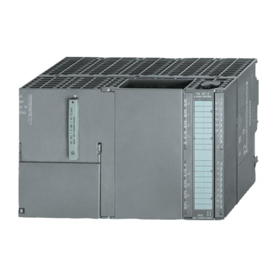
- Page 1 SIMATIC FM 357 2 Getting Started Edition 03/2000 First Steps in Commissioning...
-
Page 2: Hardware And Software Requirements
This Guide uses a concrete example to guide you through 5 start-up steps in the order given below until you have obtained a functional application. You will then be able to traverse an axis and get to know and try out the basic hardware and software functions of your FM 357-2. The references to the Manual are intended to give you an initial overview of the information contained in the Manual. - Page 3 Test: Switch on the supply on the power supply module. If the connections are correct, LEDs “DC 5V” (green) on the CPU and FM 357-2 will light up. Installing firmware from the memory card Proceed as follows: Insert the memory card with the firmware to be installed into the control switched-off. Switch the start-up switch to position A.
- Page 4 Linking into user program If you have not yet created a project, proceed as follows: File ³ Assistant Start the SIMATIC Manager and create a new project using the guided dialogs via “New project” (assign a project name). Select the SIMATIC 300-Station.
- Page 5 Parameterizing the FM 357-2 Open your project in the SIMATIC Manager. Select the SIMATIC 300-Station. Open the S7 Hardware Configuration screen by selecting com- Edit ³ Open mands Object. Select the FM 357-2. Edit ³ Object Properties Select commands to start the “Properties – FM 357-2 4AxisControl – (R0/S4)”...
- Page 6 Proceed as follows: Close “Parameterize FM 357-2” and “S7 Hardware Configuration”. File ³ Open example project “zEn16_01_FM357-2_BF_EX” in the SIMATIC Manager by selecting Open... ³ Projects. Select the S7 directory “EXAMPLES” in this project. This directory contains: a “Symbols” file, a “Sources” directory and a “Blocks” directory. SIMATIC 300-Station ³...