Advertisement
Quick Links
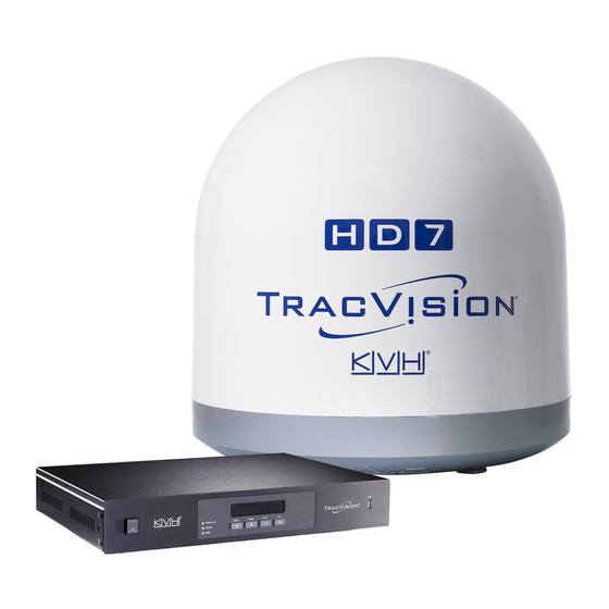
TracVision HD7 LNB
Replacement Instructions
Technical Support
If you need technical assistance, please contact KVH Technical Support:
North/South America, Australasia:
Phone: +1 401 847-3327
Email: support@kvh.com
The following instructions explain how to replace
the LNB in a TracVision
NOTE: Your antenna might have parts that differ from
those pictured in this document. Such differences have no
bearing on the instructions unless noted otherwise.
Tools Required
This procedure requires the following tools:
• #2 Phillips screwdriver
• 5/16" open-end or box wrench
• 7/16" open-end or box wrench
• 11/32" open-end or box wrench
• Flush cutters
• 7 mm open-end wrench (supplied in kit)
• #2 Phillips torque screwdriver or torque
wrench with a 11/32" hex bit set to 21 in.-lbs
• Torque wrench with:
5/16" bit (11 in.-lbs)
7/16" bit (15 in.-lbs)
7 mm hex bit (11 in.-lbs)
KVH, TracVision, and the unique light-colored dome with dark contrasting baseplate are registered trademarks of KVH Industries, Inc.
All other trademarks are property of their respective companies. The information in this document is subject to change without notice.
No company shall be liable for errors contained herein. © 2017 KVH Industries, Inc., All rights reserved. 54-0667 Rev A | 72-0429 and 72-0430
®
HD7 antenna.
Europe, Middle East, Africa, Asia-Pacific:
Phone: +45 45 160 180
Email: support@emea.kvh.com
Figure 1: HD7 LNB
1
Advertisement

Related Manuals for KVH Industries TracVision HD7 LNB


Summary of Contents for KVH Industries TracVision HD7 LNB
- Page 1 All other trademarks are property of their respective companies. The information in this document is subject to change without notice. No company shall be liable for errors contained herein. © 2017 KVH Industries, Inc., All rights reserved. 54-0667 Rev A | 72-0429 and 72-0430...
- Page 2 Step 1 - Disconnect Power and Remove the Figure 2: Radome Screws Radome Follow the steps below to disconnect power and remove the radome. a. Turn off the ACU. Then unplug both the ACU #10-32 Radome power cable and the SWM power inserter Screw power cable to disconnect all power from the (x6 or 8)
- Page 3 Step 2 - Replace the LNB Figure 3: Hall Effect Magnet Follow the steps below to replace the LNB. a. If you are replacing a Tri-Americas LNB, use a 5/16" wrench to remove and discard the two #6-32 lock nuts and washers securing the Hall Effect magnet fixture to the gyro bracket.
- Page 4 d. Cut and discard the two tie-wraps securing the Figure 6: Scuff Plate, RF Connectors, and Tie-Wraps scuff plate and discard the plate. Then cut and discard the tie-wrap securing the RF cables (see Figure 6). e. Using a 7/16" open-end wrench, disconnect the four RF cable connectors from the LNB (see Figure 6).
- Page 5 n. Secure the RF cables to the back of the LNB and Figure 9: Tie-Wrap on the Back of the LNB lower left eyelet with tie-wraps (supplied in kit) (see Figure 9 and Figure 10). o. Secure the skew cable wrap to the LNB with a new P-clip (supplied in kit) (see Figure 10).
-
Page 6: Step 4 - Update The Software
Step 3 - Install Radome and Apply Power Figure 12: Radome Screws Follow the steps below to reinstall the radome and reconnect power. a. Inspect the inside of the antenna to make sure you have not left any tools or debris inside. #10-32 Radome b.