Table of Contents
Advertisement
Instruction Manual
and Parts List
Integrated Energy Saving
Direct Drive Motor
Lockstitch Sewing Machine
SINGER and the Cameo "S" Design are exclusive trademarks of The Singer Company Limited S.à r.l. or its Affiliates.
©2018 The Singer Company Limited S.à r.l. or its Affiliates. All rights reserved.
141G
20CE
30CE
20CF (With U.T.T)
30CF (With U.T.T)
Advertisement
Table of Contents

Related Manuals for Singer 141G Series


Summary of Contents for Singer 141G Series
- Page 1 20CE 30CE 20CF (With U.T.T) 30CF (With U.T.T) SINGER and the Cameo "S" Design are exclusive trademarks of The Singer Company Limited S.à r.l. or its Affiliates. ©2018 The Singer Company Limited S.à r.l. or its Affiliates. All rights reserved.
-
Page 2: Table Of Contents
Contents 1 Safety Instructions Important Safety Instructions Safe Operation 2 Product Description and Machine Specification Product Description Machine Specification Motor specifications 3 Setup and Adjustment Instructions Table Cut-Out Drawing Oil Reservoir Installation Lubrication Rotating Hook Oil Supply Adjustment Needle Attachment Machine Threading Winding the Bobbin Thread Bobb... - Page 3 Contents Maintenance Machine Head Cleaning Lubrication Safety Inspection Trouble Shooting Parts List Frame and Micellaneous Cover Components Arm Shaft and Thread Take-up Lever Components Needle Bar, Upright Shaft and Rotating Hook Driving Shaft Components Presser Bar Components Feed Mechanism Components Thread Trimmer Components Specific parts for 141G-30CE / CF Lubrication Components...
-
Page 4: Safety Instructions
When the operator is not run- cations of use should be followed. ning the machine. manual, and use it Singer will not be held responsible · as reference when for any damage caused by unau- with the eyes or skin, washed the necessary. -
Page 5: Safe Operation
· · To avoid the risk of electric shock, If you machine is equipped with do not open the motor wiring box a servomotor, it does not make Safe Operation and do not touch the components noises while being driven.To avoid assembled inside the wiring box. -
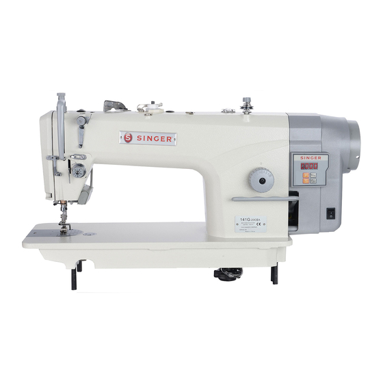
Page 6: Product Description And Machine Specification
Product Description and Machine Specification Integrated Energy Saving Direct Drive Lockstitch Sewing Machine Product 141G-20CEA / -30CEA (Without Auto Thread Trimmer) Description 141G-20CFA / -30CFA (With Auto Thread Trimmer) Integrated Energy Saving Direct Drive Lockstitch Sewing Machine Instruction Manual and Parts List... -
Page 7: Machine Specification
Machine Specification Table1 - Machine Specification Height of Needle Maximum Stitch Singer Presser Foot Hook Electric Needle Motor Speed Length Application Lubrication Power Hand / Knee Stroke Device Model Type Cat. [mm] 141G-20CEA 220V Light to 1955-01 5,000 5.5 / 13.0 30.7... -
Page 8: Setup And Adjustment Instructions
Setup and Adjustment instructions For 141G-CE / 141G-CF Fig.I Table Cut-Out Formica Drawing Fig. I Fig.II Figure 1 Integrated Energy Saving Direct Drive Motor Lockstitch Sewing Machine Instruction Manual and Parts List... -
Page 9: Oil Reservoir Installation
The oil reservoir should rest on the portion of the table and other two four corners of the machine table rubber cushion ‘2’ on the hinge side groove. ‘B’. Oil Reservoir Two rubber seats ‘ 1’ for supporting Then, the oil reservoir ‘3’ is placed. Installation the head portion on the operator side ‘A’... -
Page 10: Lubrication
Before turning the machine on, When you operate the machine af- fill oil reservoir ‘1’ with sewing ter lubrication, you will see splash- machine oil up to ‘HIGH’ mark ‘A’ ing oil through oil sight window ‘2’ Lubrication (Figure 6). if the lubrication is adequate. -
Page 11: Rotating Hook Oil Supply Adjustment
How to check the hook oil supply Sample showing the appropriate amount of oil Rotating Hook Unused machine should run idle The amount of oil can be adjusted for 3 minutes (Moderate intermit- according to the different sewing Oil Supply tent operation). -
Page 12: Needle Attachment
Turn the hand wheel until the needle Insert the needle in the direction of bar reaches the highest point of its the arrow until it will go no further. stroke. Tighten the screw '2'. Loosen screw '2' and hold needle Needle Make sure the long groove ' C' of the '1' with its indented part 'A' facing... -
Page 13: Winding The Bobbin Thread
setscrew ‘4’ and move the bobbin 1. The bobbin is pushed into the winder adjusting plate ‘5’ to the bobbin winder spindle ‘1’ until it direction of ‘A’ (Decrease) or ‘B’ will go no further. Winding the (increase). Then, tighten 2. -
Page 14: Bobb In Case Attachment
Fix the bobbin into bobbin case with that the thread open end is Bobbin Case directed to the left as observed from you. Attachment Pass the thread through thread slit ‘A’, and pulls it in direction ‘B’. By doing so, the thread will pass under the tension spring and come out from notch ‘B’. -
Page 15: Thread Take-Up Spring Adjustment
3.11 The adjustment of the stroke of the Loosen setting screw '4' and turn thread take-up spring the tension post '3'. Loosen setting screw '2'. Turn the tension post '3' clockwise Thread (in direction A), the pressure of the Turn the thread tension post '3' Take-up Spring spring will be increased. -
Page 16: Knee Lifter Height Adjustment
3.13 When using the knee lifter, the stan- Caution dard height of the presser foot is When the presser foot lift to over 10 10mm. mm or more, be sure that the needle Knee Lifter You can adjust the presser foot lift bar ‘2’... -
Page 17: Pedal Adjustment
3.16 Installing the connecting rod. Move the pedal ‘3’ to the right or left as illustrated by the arrows so that Pedal the motor control lever ‘1’ and Adjustment connecting rod ‘2’ are straightened. Adjusting the pedal angle. The pedal tilt can be freely adjusted by changing the length of the con- necting rod ‘2’. -
Page 18: Needle To Rotating Hook Relation Adjustment
3.18 Adjusting the height of the needle Adjusting the position of the rotat- ing hook Turn the hand wheel until the needle Loosen two rotating hook setscrews Needle to bar '2' has been at the lowest point, and turn the hand wheel until the Rotating loosen the setscrew '1'. -
Page 19: Thread Trimmer Adjustment
3.19 Adjustment of the thread trimming Adjusting the position of the cam position. (Figure 24) counter and the moving knives. (Figure 26) Turn the hand wheel until the needle Thread bar goes from the bottom up to 5.0 When the thread trimming shaft Trimming with the roller ‘3’... -
Page 20: Movable And Fixed Knives Position
3.20 Removing the fixed knife (Figure 27) Tilt the machine head until it stops. Movable Remove the screw ‘1’ and rotating and Fixed hook positioner ‘2’. Knives Position Remove the screw ‘3’ and the fixed knife ‘4’. Adjustment (For 141G-xxCFx Only) Figure 27 Removing the movable knife (Figure 28) -
Page 21: Height And Tilt Of The Feed Dog
3.21 Adjust the height in accordance For adjusting of the height of the with the material to be used. feed dog. Loosen screw ‘2’ of crank ‘1’. When the feed dog ’A’ is at its Height and highest position, the teeth should Move the feed bar up or down to Tilt of the be above the top surface of the... -
Page 22: Feed Timing Adjustment
3.22 eye are flush with top surface of Loosen screws ‘2’ and ‘3’ in feed throat plate when the feed dog de- eccentric cam ‘1’, move the feed cends below the throat plate. eccentric cam ‘1’ in the direction Feed Timing of the arrow or opposite direction To advance the feed timing in order of the arrow, and firmly tighten the... -
Page 23: Function Of One-Touch Switch
3.23 Needle up or stitches correction If the machine stops at intermediate and press the switch ‘1’, the needle Function of raised up to the up position. One-Touch If the machine stopped at the end Switch of the each seams, the swithc ‘1’ is press to correct by one stitch for- ward. -
Page 24: Maintenance
Maintenance Clean the machine periodically with a soft and dry cloth to remove the excess of dust on the machine head. Machine Head Do not use any kind oflacquer thin- Cleaning ner to wipe the surface. If the machine was idle for a long time, lubricate the machine accor- ding to the instructions of topics Lubrication... -
Page 25: Troubleshooting
Troubleshooting Problems Possible Causes Possible Solutions 1. Needle is installed wrong 1. Install needle correctly 2. Wrong needle type or size 2. Use proper needle for fabric and thread 3. Needle is bent 3. Replace needle Needle break 4. Wrong relation with rotary hook 4. - Page 26 Problems Possible Causes Possible Solutions 1. Thread take-up lever highest position wrong 1. Set thread take-up lever highest position correctly Needle thread 2. The needle thread is too short 2. Use proper needle for fabric and thread comes out of 3.
- Page 27 Memo Instruction Manual and Parts List Integrated Energy Saving Direct Drive Lockstitch Sewing Machine...
-
Page 28: Parts List
Parts List... -
Page 29: Frame And Micellaneous Cover Components
Frame & Miscellaneous Cover Components 9 10 Integrated Energy Saving Direct Drive Lockstitch Sewing Machine Instruction Manual and Parts List... - Page 30 No. Part No. Description 30 20 Frame & 1281-01-20 Machine frame Miscellaneous 1230-01-01-02 134-02-01 Bobbin winder assembly Cover 1281-05-13 Bobbin thread tension assembly Components 1281-05-14 Pre-tension assembly 101-03-14 Two hole thread eyelet 1281-05-12 Thread tension assembly 101.03-23 Thread release pin 1280-01-21 Face plate 1280-01-22...
-
Page 31: Arm Shaft And Thread Take-Up Lever Components
Arm Shaft and Thread Take-Up Lever Components Integrated Enegy Saving Direct Drive Lockstitch Sewing Machine Instruction Manual and Parts List... - Page 32 No. Part No. Description Arm Shaft 11-80151550-01 Set screw SM 15/64 x 28 L=11 1281-01-30 Thread take-up lever assembly and Thread 21-08008160-01 Counter weight protecting plate Take-Up Lever 11-60181630-01 Scew SM 9/32 x 28 L=16 Components 31-04424000-09 O ring Set screw SM 9/32 x 28 L=16 11-80181650-01 Screw SM 1/4 x 40 L=6 11-80160610-01...
-
Page 33: Components
Needle Bar, Upright Shaft, and Rotating Hook Driving Shaft Components Integrated Energy Saving Direct Drive Lockstitch Sewing Machine Instruction Manual and Parts List... - Page 34 No. Part No. Description Needle Bar, Rubber plug 101-03-07 1281-01-25 Needle bar bushing (upper) Upright Shaft, 1281-05-32 Needle bar and Rotating Needle bar connection 120-02-07 Hook Driving 11-60090620-01 Screw SM 9/64 x 40 L=6 Slide block 120-02-25 Shaft 101-03-08 Needle bar bushing (lower) Components 11-60080520-01 Screw SM 1/8 x 44 L=5...
-
Page 35: Presser Bar Components
Presser Bar Components Integrated Energy Saving Direct Drive Lockstitch Sewing Machine Instruction Manual and Parts List... - Page 36 No. Part No. Description 30 20 Presser Bar Hand lifter 101-04-13 21-03810080-01 Components Washer 11-30091020-01 Screw SM 9/64 x 40 L=10 31-04018000-09 Rubber ring 1281-01-10 Hand lifter cam assembly 101-04-20 Hand lifter link screw SM 5/16 x 24 101-04-21 Washer plate 101-04-19 Hand lifter link assembly 101-04-32...
-
Page 37: Feed Mechanism Components
Feed Mechanism Components Integrated Energy Saving Direct Drive Lockstitch Sewing Machine Instruction Manual and Parts List... - Page 38 No. Part No. Description Feed 1281-01-43 Feed regulator connecting rod 1255-05-09 Feed regulator pin Mechanism 11-60090620-01 Screw SM 9/64 x 40 L=6 Components 1255-05-05 Feed regulator 12-80500612-01 Bolt socket M5 L=6 11-80150612-01 Screw SM 15/64 x 40 L=6 1255-05-07 Feed regulator bushing 1255-05-06 Feed regulator hinge pin 124-08-07...
- Page 39 Feed Mechanism Components Integrated energy Saving Direct Drive Lockstitch Sewing Machine Instruction Manual and Parts List...
- Page 40 No. Part No. Description Feed 11-00090620-01 Screw SM 9/64 x 40 L=6 101-06-07 Feed rocker shaft connecting rod pin Mechanism 101-06-06 Feed rocker shaft connecting rod Components 101-06-42 Feed driving shaft crank (front) assembly 11-40111025-01 Screw SM 11/64 x 40 L=10 25-15000000-08 Retaining ring 101-06-26...
-
Page 41: Thread Trimmer Components
Thread Trimmer Components 30 31 Integrated Energy Saving Direct Drive Lockstitch Sewing Machine Instruction Manual and Parts List... - Page 42 No. Part No. Description Thread Screw SM 1/8 x 40 L=7 11-00580720-02 13-60582420-02 Nut SM 1/8 x 40 Trimmer 158-09-04 Fixed knife Components 11-20090520-01 Screw SM 9/64 x 40 L=5 11-10110622-01 Screw SM 11/64 x 40 L=6 Movable knife 158-09-13 1255-06-01-02 Knife bracket 1255-06-01-03...
-
Page 43: Specific Parts For 141G-30Ce / Cf
Specific Parts for 141G-30CE / CF Instruction Manual and Parts List Integrated Energy Saving Direct Drive Lockstitch Sewing Machine... - Page 44 No. Part No. Description Specific Feed drive eccentric cam 101-06-02XH 101-06-06XH Feed rock shaft crank connecting rod Parts for 101-06-04XH Thrust collar 141G-30CE / CF Thread take-up lever assembly 1281-01-32A Needle plate B20 101-06-36H Needle plate 120-01-22 120-04-04 Feed dog 101-04-01XH Presser adjusting thumb screw 101-04-02XH...
-
Page 45: Lubrication Components
Lubrication Components Instruction Manual and Parts List Integrated Energy Saving Direct Drive Lockstitch Sewing Machine... - Page 46 No. Part No. Description Lubrication Oil sight window 101-08-25 31-20024000-09 Components Rubber ring 101-08-19 Main shaft oil tube 42-05003000-00 Oil return tube 11-40120625-01 Screw SM3/16 x 28 L=6 120-07-07 Oil return tube felt 101-08-28 Oil return tube holder 1283-02-05 Oil feet presser 101-08-16 Oil pump suppor M8 11-40111025-01D...
-
Page 47: Oil Reservoir Components
Oil Reservoir Components Integrated Energy Saving Direct Drive Lockstitch Sewing Machine Instruction Manual and Parts List... - Page 48 No. Part No. Description Oil Reservoir Knee presser lift rod 101-09-02 101-09-01 Oil reservoir Components 101-09-03 Oil reservoir gasket 101-09-05 Rubber cushion (small) 11-70200720-01 Screw SM 5/16 x 24 L=7 31-06224000-09 Rubber ring 101-09-07 Knee lifter connecting rod 101-09-08 Spring 24-10000000-09 E-ring 10 101-09-10-00...
-
Page 49: Machine Accessories
6.10 Machine Accessories No. Part No. Description 20 30 101-12-01 Machine hinge plate 120-09-02 Machine hinge rubber cushion 101-12-03 Nail 1955-01 3 needles per packet size 14 1955-01 3 needles per packet size 18 101-12-15 Screw driver (large) Screw driver (medium) 101-12-16 Screw driver (small) 101-12-17... - Page 50 SINGER and the Cameo "S" Design are exclusive trademarks of The Singer Company Limited S.à r.l. or its Affiliates. ©2018 The Singer Company Limited S.à r.l. or its Affiliates. All rights reserved. www.singer.com...